INTRODUCTION
Designing of the conveyors as technologi-cal devices is a comprehensive set of tasks to be solved in basic sequential steps. Currently, vari-ous design tools with computer support are used to design a physical model (CAD) according to predefined requirements. the physical model is static without any possibility of verifying its functional model as a moving mechatronic unit. The conveyor as a mechatronic device consists of a physical mechanical model, a motion device (motor + gearbox) and a controller that controls the movement of the motor and the conveyor it-self. The development of the control system is carried out during the design of the conveyor’s physical model itself, but it is generally tested on a real physical conveyor and assembled convey-er, so putting it into operation is solved directly on the conveyor.
The virtual commissioning as the simulation tool allows you to verify the control program even earlier before the real commissioning as discussed elsewhere [1, 2]. This tool is an experimental method where the real conveyor is replaced by a computer model. Conveyor units represent a very important part within majority of logistic systems. Their role is to transport variety of materials and foster the functioning of individual technological processes [3]. On the conveyor model, it is pos-sible to test and perform a large number of varia-tions and situavaria-tions without physical intervention to the actual conveyor and possible damage to the functional parts, as Reinhart said [4]. Reliable, trouble-free operation of continuous transport systems requires regular monitoring and evalua-tion of each operaevalua-tional indicator [5]. These ex-periments can then be evaluated and the control system optimized, e.g. with respect to the material flow [6], the times and overall energy consump-Volume 12, Issue 4, December 2018, pages 164–171
https://doi.org/10.12913/22998624/100349
The Simulation of Conveyor Control System
U
sing the Virtual
Commissioning and Virtual Reality
Roman Ružarovský
1*, Radovan Holubek
1, Daynier Rolando Delgado Sobrino
1,
Matej Janíček
11 Institute of Production Technologies, Faculty of Materials Science and Technology in Trnava, Slovak University
of Technology in Bratislava, Jána Bottu 2781/25, 917 24 Trnava, Slovakia * Corresponding author’s e-mail: [email protected]
ABSTRACT
Designing of the conveyors and its control system with control program through the design tool “Virtual Com-missioning” is very important in the digital era Industry 4.0. Virtual Commissioning was recently used to perform realistic virtual simulations in the early stages of development processes in automation of the conveyors too. The
main benefit is the possibility of integrating and testing the control system through the simulation on the virtual
model even before physically constructing the conveyor. The contribution focuses on the possibilities of trans-forming a real conveyor into a virtual model in the Siemens Tecnomatix Process Simulate program and integrating the Siemens S7-300 real control system to control the conveyor itself. In the model it was allowed to test and per-form numerous variations and situations without physical intervention into the real conveyor and possible damage functional parts including through virtual reality. These experiments were subsequently evaluated and the control
system optimized with respect to material flow and the developed PLC code on virtual model was verified on real
conveyor control system.
Keywords: simulation, conveyor control, sensor integration, virtual commissioning, virtual reality.
Research Journal
Accepted: 2018.11.05tion by Zhang [7] during transporting the mate-rial. Simulation is a method that allows you to ex-periment with the conveyor model before it was physically in operation [8]. First and foremost is to create a model for simulation. The model is a simplified representation of the conveyor system used of the modulated elements, rules and fea-tures, whose layout, interconnection, but mainly functioning, corresponds to the real system. So the model is quite similar to the real system we are looking at from a certain point of view.
ANALYSIS OF THE PROBLEMATICS AND
OBJECTIVES
The aim of the research is to create an ex-perimental model to explore the possibility of implementing a conveyor control system. This model will be based on a virtual simulation model of the conveyor.
vices, air 3-axes Cartesian type manipulator with a pneumatic gripper, a measuring device for mea-suring the size of drill holes and a belt conveyor for conveying the pallets with products “Base-plate”, Figure 1.
Belt conveyor and its control system
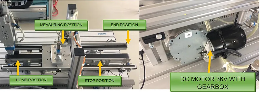
The basic concept of the conveyor is a belt driven by a 36V DC DC motor with a gearbox from Dunkermotoren GmBH. The conveyor is 700 mm in length, Figure 2.
The conveyor is designed to transport the “Baseplate” workpieces stored on the system pallet. Through the DC motor, it is possible to transport one palette from the manipulator to the measuring system at the end of the conveyor or in the opposite direction. The pallet can be stopped in 4 positions at the end of both sides of the conveyor and at the measuring point in both directions. he position is indexed by an automat-ic pneumatautomat-ic stop mechanism and controlled by the Festo induction sensor SIEN-M8. The pres -ence of the workpiece is detected through the Festo optical gate. The speed of the conveyor is determined by the speed of the DC motor and the gearbox and is unchanged.
Fig. 1. Automated Quality-handling station with
con-veyor in iCIM flexible manufacturing system
Objectives
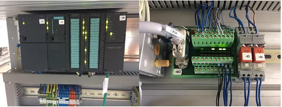
The requirement for conveyor control is the integration of automation into a real control sys-tem. It is used PLC S7-300 control system from Siemens, which controls the manipulator itself and the operation of the measuring device. Specifically, the CPU 313C with the integrated power supply and the CP343-1 communication module on the ProfiNet communication protocol, Figure 3.
It is necessary to integrate the conveyor move-ment itself, the pallet position sensing and the pres-ence of the workpiece on the pallet. It is also neces-sary to integrate the HMI for the manual operation of the conveyor itself. The Virtual Commissioning tool is used for testing of the various scenarios without the need for a physical device in the con-trol program developing [10]. Experiments will be evaluated and the control program optimized with respect to the required material flow. Testing the virtual conveyor model for better realistic viewing will be performed through virtual reality.
RESULTS
In order to be able to test and validate the control program on a virtual model, software that allows it to be used. As a simulation soft-ware, we chose Tecnomatix Process Simulate, which allows you to create discrete time and/or event simulations for automated devices and in-dustrial robots. He can communicate with control systems, for example, through the OPC Server, as is described in the Work Flow by Popovič et al. [11]. Virtual Commissioning – need to create
OPC connection – connection between PLC and Process Simulate. The simulator is equipped with a variety of tools to verify the process, including motion, execution, cycle time, and collision de-tection. The simulation project must include the following phases; i: System analysis and problem definition, formulation of simulation objectives, ii: Collection and processing of process infor-mation, estimation of parameters and types, iii: Creating an abstract logic model, iv: Building a model on a computer, v: Verifying and testing the model, vi: Planning and preparation of simulation experiments, viii: Implementation of simulation experiments (model factor changes) or model modification, viii: Evaluation and processing of experimental results.
Virtual Model of the Conveyor
primarily used in the automobile and aerospace industries, it can be used for any similar manu-facturing industry application [12].
Integration of the model into simulation
This virtual model has to be integrated into the simulation. Firstly, it is necessary to create a simulation model according to the model of the real system [13]. This means that it is nec-essary to create the kinematics of the model it-self [14] and to define the conditions in which it will move, how much the trajectory will, how the
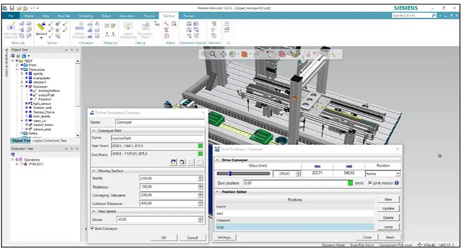
limits and the dynamic parameters (load, speed, acceleration) will be defined. On this system, we can perform simulation experiments at a later stage. When defining a conveyor, it is necessary to define a curve that will move the palette (mo -tionPath), start point, end point, Moving Surface, Max. Speed, definition of Skid, Figure 4.
After defining the parameters, it is possible to design the positions in which the palette can be stopped (Pose Editor) in the simulation model and to manually test the movement itself via the Drive Conveyor command, where the real value of the position is displayed in mm. A virtual model can Fig. 4. Definition of the kinematics parameters of the simulation model for the conveyor
test how kinematically, even in virtual reality. By testing this, it is possible to realistically check the virtual model for whether it corresponds to real reality. It is also possible to check in detail in 3D view, whether there are collisions between the moving parts and using virtual reality to check the individual stop points with certain accuracy [15, 16]. The HTC Vive Headset was selected for vir-tual reality. In Figure 5 is a preview of the Virvir-tual Reality Tecnomatix Process Simulate module.
Design of the behavior model of the conveyor and sensors integration
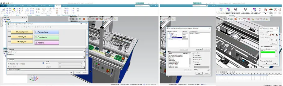
In order to integrate the control system into the virtual conveyor model and thus test the model itself via the PLC controller, several steps need to be taken. One condition is to create a conveyor model behavior. The behavior model is designed to simulate the logical and time-based behavior of real resources compared to the connected control units and therefore con-sists primarily of the individual simulation com-ponents of the devices used in the real device. In Fig. 6 on the left is a model of logic behavior with defined parameters (ChangeSpeed, motor_ on, change_dir). The conveyor control entities (digital inputs and outputs) are also defined, Fig. 6 in the centre. The digital outputs are designed to control the DC motor and move the conveyor away from the manipulator and reverse. A very important factor is the definition of sensors for pallet position detection (inductive sensors) and the definition of the presence of the workpiece through the gate (Set Detection Area, Interfer-ence with). In Figure 6 on the right is a red light beam that simulates the infrared beam of light from the optical gate.
Integration of the control system into a virtual model
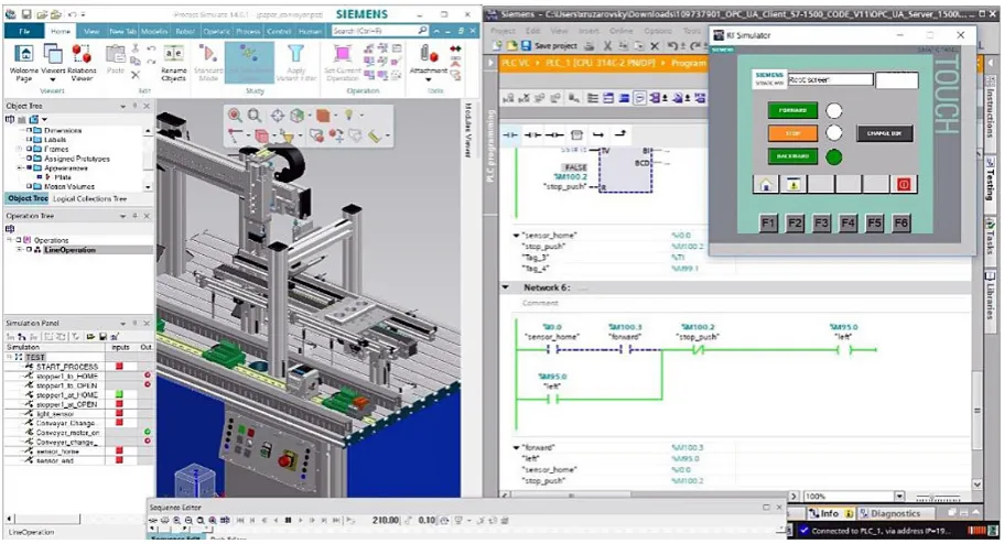
The actual virtual commissioning is done by connecting the simulation model with all the at-tributes mentioned in the previous points and the PLC (virtual or real) control system via standard -ized interfaces (OPC, Emulator, Bus). If a con-nection has been made, it is possible to test this connection through the “Sequence Editor”. This editor allows you to test individual operations in time or event simulation. The simulation SIMAT -IC S7-PLCSIM simulator was used to initially test simulation and PLC connection. The pro -gram was created via the TIA Portal V14, where the KTP600 HMI panel simulator was connected. The connection of the virtual conveyor model and the TIA portal has been successful, all digital in-puts and outin-puts have been defined with address -es that must be the same whether in the virtual model or in the control program via TIA Portal. In Fig. shows the virtual conveyor model along with the HMI simulator in the operating mode and the test signals on the Simulation Panel, where the green colour is a logical 1 and a red logic 0. These individual signals can also be activated / forced directly through the Simulation Panel, Figure 7.
Testing the control program on a virtual model
After verification of the conveyor simulation model as well as virtual reality and achieving integration between the model and the control system, it is possible to test various program-ming scenarios and optimize the PLC control code directly on the virtual model. The virtual conveyor model behaves conventionally against the control program. In addition, a HMI panel Fig. 6. Definition of the behavior model, parameters with connected signals and editing of the photoelectric
with basic signals for manual forward and re-verse conveying of the conveyor was also tested, as can also be seen in Figure 8.
DISCUSSION
The optimization of the control program has been performed with respect to the virtual model
created according to material flow requirements. This created control program was then imple-mented into the actual PLC S7-300 control sys -tem on a real conveyor station. The PLC code was generally fine and validated, the differences were only in timer settings. In the future, it would be necessary to connect the real control system di-rectly to the virtual conveyor model and test real model management to get closer to real PLC opti -Fig. 7. Definition of the behavior model and parameters with connected signal
mization. A very important factor is also the PLC operating cycle and real-time communication, which the PLC simulation model does not allow.
Overall, virtual commissioning is a very in-teresting way to save time in developing new conveyors in view of the development of the con-trol program for the concon-trol system. The benefits achieved by the simulation application should be greater than the costs needed to implement the simulation and system improvements. The deci-sive criterion that simulation can be used in prac-tice will be the benefit of its use. The benefits can be divided into quantitative and qualitative. When deciding on a simulation project, a simple rule will apply: Simulation will be warranted if the direct simulation benefits are greater than simulation costs. In many cases, the simulation objective is not a direct economic effect. A sup -plier of production or transport systems can, for example, demonstrate through simulation their functionality, performance or reliability, which may improve its market position. In order to maximize the effect of simulation, the time at which the simulation is realized varies consider-ably. The simulation should be used in the early stages of the project, as the greatest potential for improving the system’s parameters can be achieved in the early stages, and the associated costs are the lowest in these phases. There are only a few degrees of freedom for change and improvement in the process of implementation and operation, and most of these improvements are associated with high additional costs that of-ten can outweigh the benefits of improvement. This implies that correct and timely decisions have inherently higher benefits than optimization in subsequent stages of the project.
CONCLUSION
Simulation alone cannot give you an optimal solution, it only allows you to examine the im-pact of the decision on the simulation model and gives you the choice of the best of them. Virtual commissioning based on verified research has its own perspective because it allows you to test and verify the PLC code on a virtual model that takes place in a traditional design only when an auto-mated device is built and any hardware changes cost money and time. Virtual commissioning re-quires a realistic digital twin and spends a lot of time with kinematics, behavioral modelling, and signal generation overall. However, when we
au-tomate some operations, it is a technology that has great potential and future in designing auto-mated devices.
Acknowledgements
This paper has been supported by the project KEGA-021STU-4/2018. Development of a labo -ratory for the design and maintenance of produc-tion systems supported by the use of virtual real-ity. This support is gratefully acknowledged.
REFERENCES
1. Dahl M., Bengtsson K., Bergagard P., Fabian M.,
Falkman P. Integrated Virtual Preparation and Commissioning: supporting format methods dur-ing automation systems development.
IFAC-Pa-persOnLine 49(12), 2016, 1939–1944.
2. Bergert M. and Kiefer J. Mechatronic Data Models
in Production Engineering. IFAC Proceedings Vol-umes 43 (4), 2010, 60-65.
3. Molnár V., Fedorko G., Andrejiová M., Grinčová A., Michalik P. Online moniroring of a pipe con
-veyor. Part I: Measurement and analysis of selected operational parameters, Meas. J. Int. Meas. Con
-fed. 94 (2016) 364-371 https://www.sciencedirect. com/science/article/pii/S0263224116304791
4. Reinhart G. and Wünsch G. Economic application of virtual commissioning to mechatronic. Produc-tion Engineering – Research and Development
1(4), 2007, 371–379.
5. Fedorko G., Liptai P., Molnár V. Proposal of the methodology for noise sources identification and
analysis of continuous transport systems using an acoustic camera. Eng Fail Anal., 83, 2018, 30-46. 6. Seidel S., Donath U. and Haufe J. Towards an inte
-grated simulation and virtual commissioning envi-ronment for controls of material handling systems. Proceedings of the 2012 Winter Simulation Con-ference, 2012.
7. Zhang S., Xia X. Modelling and energy efficiency
optimization of belt conveyors. Applied Energy
88(9), 2011, 3061-3071.
8. Puntel-Schmidt P. and Fay A. Levels of Detail and Appropriate Model Types for Virtual Commission
-ing in Manufactur-ing Engineer-ing, IFAC-Paper
-sOnLine 48(1), 2015, 922-927.
9. Holubek R. Using Virtual Reality tools to support
simulations of manufacturing instances in
Pro-cess Simulate: The case of an iCIM 3000 system. MATEC Web of Conferences 137, 2017.
10. Vermaak H. and Niemann J. Virtual commission
entists 2013 Vol II, IMECS 2013, March 13 - 15,
2013, Hong Kong, 2013.
13. Lonkwic P., Rozylo P. and Debski H. Numerical
and experimental analysis of the progressive gear
16. Lorenz M. CAD to VR – a methodology for the au -tomated conversion of kinematic CAD models to
virtual reality. Research and Innovation in Manu -facturing: Proceedings of the 48th CIRP Conference