Effective Throughput Based Approaches in Avoiding
Selective Jamming Attack by Achieving Privacy in
Wireless Networks
BKSP. Kumar Raju
Department of Computer Science and Engineering JNTUK University college of Engineering, VZM. AP, India
Email: [email protected]
R. Rajeshwara Rao
Department of Computer Science and Engineering JNTUK University college of Engineering, VZM. AP, India
Email: [email protected]
Abstract – In Jamming, all network secrets and protocol specifications can be known by intruders. However, we consider avoiding selective jamming using internal threat model. There are existing methods to prevent selective jamming namely Strong Hiding Commitment Schemes (SHCS) and Cryptographic Puzzle Hiding Schemes (CPHS). From these existing methods, it is observed that there was no guarantee of message privacy. In this paper, for ensuring privacy even after the transmission of packets to destination, we propose two methods namely Medial Node Method (MNM) and Embedding Future Key (EFK) Method. Finally, Performance evaluation is carried out with the existing methods with our proposed methods in terms of throughput and route discovery time. It is established from our experiments that proposed methods have better throughput and even better route discover time.
Keywords – Medial Node, Packet Classification, Selective Jamming, Wireless Networks.
I. I
NTRODUCTIONWireless networks are prone to diverse set of attacks due to its shared medium. Well-designed network architectures may address various security threats [2], [3], [6], [9], [12], [17], [19], [20]. However, wireless networks are even sensitive to number of attacks. From the existing security threats to be resolved, we kept our center of interest on Selective Jamming which is the recent headway on the bad side of technology. We do have various traditional jamming attacks like constant jamming, random jamming, deceptive jamming etc [1], [14], [18]. To have any of these attacks, the antagonist has to spend more vigor but the impact on the network degradation is less. Moreover, there are wide varieties of techniques to prevent several traditional jamming strategies in [5], [8], [11], [13], [16]. But, in Selective Jamming, the assaulter will expend fewer resources [10], [15] and can create drastic bad consequences. Taking this as a ground principle, we can
assign a tagline for the selective jamming as “less effort,
more impact” scheme. Assaulter who does the selective jamming will target on specific sender node (SN) and specific receiver node (RN) and thereby corrupt only the significant packets (e.g. Route REQ / REPLY, ACK etc) that travel between them. Selective jammer (SJ) node will use packet classification methods [7], [4], [15] to know whether packet is significant or not. To achieve this selective jamming, the Selective Jammer (SJ) node should be an internal part of the network which makes it to know all the network secrets in an easier way. Finally, all these
things make assaulter to perform selective jamming with less energy consumption.
In Section II, we have illustrated the procedure involved in finding selective jammer node; Section III describes preventing methods for selective jamming attacks. Then in section IV, we evaluate proposed selective jamming preventing methods with the existing methods, section V describes conclusion.
II. D
ETECTING THES
ELECTIVEJ
AMMERIf selective jamming is achieved by adversary for a packet then receiver cannot recover that packet. SJ is just like a normal node but has more computational capabilities than other nodes. We show this SJ node detection in two steps: (1) initially, we confirm whether there is a presence of selective jamming between specific SN and RN. If there is selective jamming, we will go for the next step: (2) identifying the exact node that is performing selective jamming. The corresponding procedures of these two steps are shown in the following subsections (A and B):
A. Checking the Existence of Selective Jammer
As shown in Fig. 1, SJ has targeted on SN and RN which classifies each and every packet sent by SN to RN but it only corrupts significant packets (SP). It will not do any harm to insignificant packets (IP) because corrupting only the significant packets would create more bad impact on SN and RN rather than corrupting all [7]. Moreover, this makes SJ to achieve its goal with less energy. There is a best existing method called as Packet Delivery Ratio (PDR) with consistency checks [1], which is used to detect various types of Jamming in wireless networks. We have just used the basic idea behind this and proposed a novel approach for the detection of selective jamming.Since, SJ will corrupt all the significant packets leaving the insignificant ones, the number of significant packets that are recovered at RN are zero. In Algorithm1, during the significant synchronization time (Tss), SN will
maintain a count of both significant Packets (CSP)SNand
Copyright © 2013 IJECCE, All right reserved insignificant packets (CIP)SN. These values will be used by
the SN to find SJ node existence. Moreover, during the same Tss , RN will also maintain the count of received
significant and insignificant packets from SN i.e (CSP)RN
and (CIP)RN(As shown in Algorithm 2), Where Tssis used
by both SN and RN to find whether they are under selective jamming or not. If yes, SN and RN can find the SJ node by using the concept presented in subsection B. Algorithm 1: Maintaining Count at Sender Node
1: (CSP)SN=0,(CIP)SN=0; 2: sendToDest(); 3: startTimer(Tss);
4: if Pi==SP // if packet is significant 5: (CSP)SN++;
6: else
7: (CIP)SN++; 8: end if
9: Goto(2) and repeat until timer expires; 10: Wait(tα);
We assume that during Tss, SN will send at least one
significant packet and one or more insignificant packets to RN. The time Tssshould be synchronized between SN and
RN to the maximum extent as possible. To achieve this, SN just starts its Tssafter sending its first packet; similarly,
RN Starts its Tss after receiving the first packet. This
makes Tssat SN to expire first then it waits for some time
tα, so that it may receive complaints from RN if any.
As shown in algorithm-2, If (CSP)RN=0 and (CIP)RN
!=0, after a time of Tss then RN thinks that it is under
selective jamming with source as SN. Hence RN complains to the SN by passing the parameters (CSP)RN
and (CIP)RN. Treating this complaint as significant one, the
selective jammer may jam the packet containing complaint and thereby makes it not to reach SN. To avoid this, we make RN to use existing CPHS for transferring the complaint. This may make SJ to solve the puzzle and know the values in the complaint but this solving cannot be possible on before the complaint reaches the SN. Ultimately, the complaint will be taken by the destination correctly. If once this is done, SN can prevent the selective jamming as explained in section III.
The adversary node cannot be underestimated which may intentionally leave one significant packet without corrupting it. This makes the receiver node to get failed with the condition ((CSP)RN= = 0) thereby makes RN to
create a wrong feeling that it is not under selective jamming but actually it is. So to resolve this, we change the condition from (CSP)RN= =0 to (CSP)RN< threshold,
by which RN can correctly predict the existence of selective jamming; To satisfy this condition SJ has to leave intentionally more than one significant packet between SN and RN, which SJ may not be ready to do at any case. But, how threshold value has to be fixed? Since the RN gets the correct number of insignificant packets i.e. (CIP)RN, based on this, it predicts the minimum number of
significant packets that it wants to receive within a time
interval of Tss, which is then fixed as threshold. Otherwise,
say RN has transmitted ‘n’ significant packets to SN. Then RN needs to get the same number of acknowledgments (ACK) which are treated as significant packets. So, along with ACK significant packets to be received, there may be other categories of packets which are significant. Taking this into account, threshold value can be fixed to a minimum value i.e. here ‘n’.
Algorithm 2: Maintaining Count and Complaining
1: (CSP)RN=0,(CIP)RN=0;
2: ReceiveFromSrc(); // Here source is SN 3: StartTimer(Tss);
4: Recover (Pi); // Piis any packet 5: if Recover (Pi)==success
6: if classify (Pi)!=SP //Significant Packet 7: (CIP)RN++;
8: else
9: (CSP)RN++; 10: end if 11: end if
12: If Recover (Pi) = = fail 13: Do nothing;
14: end if
15: Goto(3) and repeat until timer expires; 16: if (CSP)RN= = 0
17: if (CIP)RN!=0
18: Print “Jamming is Present”;
19: complainTo(RN,SN, (CSP)RN, (CIP)RN); 20: end if
21: end if
The SN that receives these values ((CSP)RN, (CIP)RN) will compare with its ((CSP)SNand (CIP)SN) values. Then this result will meet any of the possible cases shown below:
Case-1: More difference in CSP values of (SN, RN) but very less difference in CIP values of (SN, RN) indicates, there is Selective Jamming between SN and RN, because RN received only insignificant but not significant Packets (SP). (As already shown in Fig. 1)
Case- 2: More difference in both CSP and CIP values of (SN, RN) reveals two possible alternatives a) In Fig. 2(a), SN and RN are under continues jamming because continues Jammer sends high interference signals constantly. So, this makes both SP and IP packets not to reach RN. b) As shown in Fig. 2(b), there may be a presence of poor wireless link between SN and RN. But, there is no presence of Selective Jammer.
Case-4: As depicted in Fig. 4, less difference in both CSP and CIP values of (SN, RN) indicates no jamming. Let us say, total number of packets transmitted by SN is Pn+α. But, say RN received Pnpackets. Due to unreliability nature of Wireless network, α packets were unable to
reach RN, Whereα is very less. Hence no Jamming exists
over here. If CSP and CIP values of SN and RN are matched then also it indicates, there was no presence of jammer.
But in our paper, we address only the first case.
B. Finding the Selective Jammer
By using above cases, one can predict whether there is selective jamming between SN and RN or not. If confirmed, SN has to detect the node which is performing selective jamming. Since there are number of nodes between SN and RN, it is not an easy task to accomplish this detection. But, we resolve this by considering the weakness of SJ node. The solution is, SN simply broadcast the HELLO packet when SJ is busy such that it should not answer the HELLO packet but all the free nodes reply immediately. Since, SN does not know the state of SJ, it intentionally sends dummy significant packet (DSP) to RN by puzzling with computational capability more than that of SJ and this makes SJ to take the DSP and will be busy in solving that. The same DSP will reach the Receiver RN but it should not spend time and waste its energy in solving the dummy packet.
So, we can place a restriction as if once complaint is passed by RN to SN, it should not receive any packets directly from SN until there was no selective jamming between SN and RN. DSP means it contains significant data but it is generated randomly by SN and not useful for RN. The reply from the nodes indicates that they are free nodes (FN) and the nodes which do not reply immediately are treated as Busy Nodes (BN). By using (1), we can find the selective jammer.
{BN}= {BN}–{FN}; (1)
Fig.2. (a) Leads to Continues jamming in both significant and insignificant packets conditions.
Fig.2. (b) Significant and insignificant packet count is zero at destination due to poor wireless link
Initially, we assume all the nodes within the range of SN and RN as busy Nodes (BN). On just before sending the HELLO packet, intentionally SN makes SJ node to be in busy state, making it not to respond with the packet immediately. So, we treat the nodes that replied quickly as free nodes. Hence, SJ will not be in free nodes list. For example, if there are five nodes within the communication range of SN and RN.
Five Nodes={X, Y, Z, P, Q}
Initially, SN sends a DSP to RN, if selective Jammer node is in between SN and RN, then the DSP packet will be taken by SJ and will be busy in solving dummy packet. At that point of time, SN broadcasts HELLO packet and the nodes that are free will reply immediately.
If the replied nodes are X, Z and Q; by using (1), BN= {X, Y, Z, P, Q}-{X, Z, Q} =>{Y, P}.Among Y and P, one is the selective jammer node. To know this, SN sends another DSP to RN which makes selective jammer to spend time on the DSP. Immediately, SN broadcasts the HELLO packet. Then the nodes which are currently free will reply immediately. If the replied node is {Y}; Then, by using (1), BN={Y, P} – {Y} => {P}; here ‘P’ is the
selective jammer (SJ) between SN and RN. In general, the node in the singleton set is the selective jammer node.
To better confirm the node in singleton set is SJ, we repeat the same for µ number of iterations. This scheme works because a node which may be free during first HELLO packet may not be free during second or third and so on. This detection process may be time taken but ultimately we are detecting the culprit, who is selective jammer in our perspective.
Fig.3. Drives to Random jamming in both significant and insignificant packets conditions
Fig.4. Significant and insignificant packets difference is very less at destination since no selective jamming.
III. P
REVENTINGS
ELECTIVEJ
AMMINGA
TTACKCopyright © 2013 IJECCE, All right reserved significant packets between specific sender node (SN) and
receiver node (RN), if we make SN to send packets via an intermediate node then selective jamming may not be possible. If the intermediate node that SN wants to use is already busy then packet transfer may not be done immediately. So, instead we can make SN to select an intermediate node that is free such that it should reduce the time to travel a packet to the destination (here RN).
A
.
Medial Node
Method (MNM)-choosing an
intermediate node that is not targeted by selective
jammer.
Once RN knows that it was under selective jamming by using Algorithm-2, it selects a node (Ni) that is very closer
to it which is not within the communication range of selective jammer. Say, RN wants to send data to SN then RN uses Nias a medial node to have packet transfer to SN.
To say in detail, RN includes its address in the source field of header and destination field contains the Ni address. This makes Ni to take the packet and it by passes the same packet with small change in the header part i.e. now source address field contains the Ni address and
destination address is same (SN). Since selective jammer concentrates on the packets between specific sender and receiver, we have changed any of them by using a medial node Ni. But, there were two problems in usage of this
procedure.
Firstly, SN upon receiving the packet will come to know that sender of the packet was node Ni, not RN. But, the
actual sender of the packet is RN which we need to reveal this to SN without being known to the SJ. To achieve this, we make node Ni to keep RN address at the end of the
packet. Upon receiving this packet by SN, it looks into the header part and knows that destination is itself and the source is Ni, then it takes the entire packet with the same
perception but at the end of the packet it finds another address which belongs to the actual sender of the packet i.e. here RN. Initially, we keep a condition that if any node finds any address at the end of packet it should be treated as actual source of the packet. The reason for keeping the actual source address at the end of the packet is, selective jammer will classify the packet by taking the first few bits of the packet and if it does not include its intended sender address and receiver address, SJ ignores that packet
Second problem involved in the above procedure is, since we are using another medial node there is a chance of increase in the communication time. This communication time can even be reduced by taking closer nodes into account. For this, RN can select a closer node in two possible ways: a) Node closer to SN b) Node closer to RN. In the way of optimization, we make RN to select closer free node rather than closer node because say the closer node that was selected by RN is already busy then that closer node cannot be allotted to RN or it has to compromise with its job and then be allotted. To avoid any of these bad consequences, we make RN to select closer free node. To select a free node closer to SN by RN, it broadcasts HELLO packet. Nodes which are free will reply to that HELLO packet. We assume that, on beforehand RN knows the average time to receive a reply
from SN, say ‘x’ units of time. Upon receiving the replies
of sent HELLO packet from the free nodes, only one reply is considered which comes at time nearby ‘x’ units.
Finally, that node is declared as free node closer to SN by RN. But, in practical this process may kill some time which makes RN to select free node closer to it. To achieve this, RN simply broadcasts HELLO packets and the node which replied firstly is treated as closer free node to it.
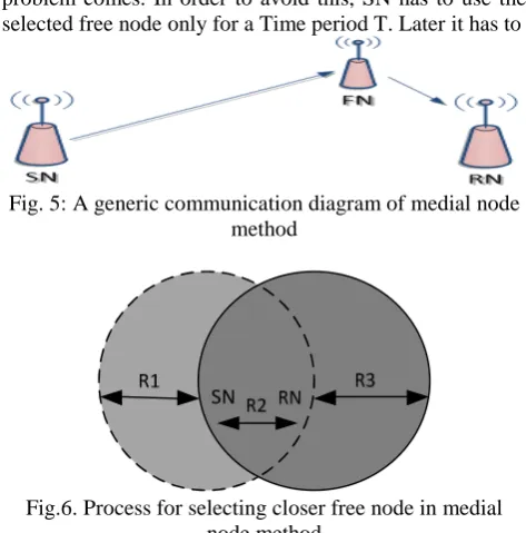
As shown in Fig.5, RN has selected a free node closer to it and can have the communication with SN via that free node, even the vice versa communications uses the same free node. As shown in Fig.6, SN has its own communication range which is indicated with dotted Circle whereas the other circle indicates the RN range. Based on Fig.6, RN communication range falls under two regions i.e. R2 and R3. As said, If RN wants to select a closer free node to SN then it may lead to increase in the communication and computation overhead. The other alternative for RN would reduce this overhead which is the selection of closer free nodes to it.
Practically, in this solution, the packet transfer time can be reduced even though SN and RN are using an intermediate node. Packets generated by SN are delivered by FN to RN but, if FN has its own packets to send or receive, then it can also be resolved to a certain extent as, each node can operate in full duplex mode [7]. That is, when FN is receiving the data from SN, it can do its own data transmissions and vice versa. But, if a free node has its own data to send and receive at same time then real problem comes. In order to avoid this, SN has to use the selected free node only for a Time period T. Later it has to
Fig. 5: A generic communication diagram of medial node method
Fig.6. Process for selecting closer free node in medial node method
that is originated from SN, but it classifies the packets that are designated only to RN. Selective Jammer node, which is more familiar for energy conservation, will prefer this.
Our schemes presented in this paper will have several benefits. Some of them are :a) privacy is achieved. Existing techniques [7] restricted the SJ node not to perform the packet classification, only for small time Sµ. Meanwhile, the packet may reach the destination. After Sµ, SJ node will solve the secured message that was transmitted between sender and receiver and thus violating privacy of the message. But in our proposed method, packet may not be taken by the SJ node and thus finally preserving privacy. b) Existing method like CPHS used the puzzles based on the Computational Capability (CC) of SJ [7]. But in our proposed technique, once SN and RN are known to each other that they are under selective jamming, they start using a free node and thereby no need to use puzzles at all. But to get rid from other hackings or threats, any secured cryptography can be used based on the requirements.
We are using a free node for accomplishing SN to RN communication but this may increase the communication time. So, SN reduced this time by selecting the free nodes that are closer to RN. Moreover, SN has to spend more energy to send the DSP, HELLO packets and for further processing’s, but we ignore this because we are benefited in several other ways like achieved privacy, have not used the puzzle generation and solving, given a flexibility to change the free nodes from time to time to reduce the burden on a single free node.
Moreover, in our paper we have assumed that there is only one selective jammer within the communication range of SN and RN. Previously, each packet is puzzled with computational capability of SJ. This makes all the nodes which are acting like receivers to spend more time because their computational power is far less from SJ. But, our proposed techniques didn’t use any puzzles and
thereby saves valuable time of nodes. Next, we will describe another method named as Embedding future key method which is also used to achieve privacy of the message even after message delivery to the destination.
B
. Embedding Future Key (EFK) Method
In the previous method, we used the concept of free node to make the message not to be known for the selective jammer which was transmitted between intended sender and receiver. Now, we will introduce a new method for the same but without using the notion of free node.
We assume, there was a symmetric initial key (SIK) at SN and RN. By using SIK, the SN encrypts the packet that contains the data and next key (Kx). Upon receiving this,
RN will decrypt the first packet it has received with SIK. This makes RN to know both the message and Kx. By
using Kx, RN can decrypt the next immediate packet sent
by SN. This process is shown in the below Fig.7. SIK is only known to SN and RN. The first packet that SN sends to RN is encrypted by SIK and can only be decrypted by RN and thereby preventing the packet classification from SJ node (we have taken only the KXand data as the packet details for better clarity).
The problem over here is, if one packet (Pi) has lost in
the network due to any reason then RN cannot decrypt any of the next packets (Pi+1, Pi+2….) that it has received from
SN because there is a interlink age between keys of the packets. This makes RN to send ACK immediately after successful decryption of each packet.
This is a good mechanism but network traffic can be increased. To reduce traffic, the number of ACK’s should
be reduced. This is done by making RN to send ACK only after the immediate receiving of unrecovered packet. In this case, the ACK sent by RN belongs to the last successful packet that it received from SN. The ACK sent by RN can also be included with some details to identify the last successful packet that it received. Upon receiving this, SN will resend the packets from next packet of the ACK received ones. This scheme makes the number of ACK’s transmission to be reduced.
But the important question to be resolved is, how can SN and RN know the SIK? This can be solved with the help of master node. Master node is just like the normal node but has more computational power and even more memory space. We will assume that, at that time of network establishment itself each node is configured with unique private key (UPK) such that a node UPK is not known to any other node except the master node. Master node stores UPK’s of all nodes. Based on these criteria’s
SIK from RN can be transmitted to SN in the following (as shown in Fig. 8).
Fig.7. Embedding Future Key method for achieving privacy
Fig.8. Sequence involved in SIK transfer from RN to SN As step-1, after RN knows that it was under selective jamming it will transmit randomly generated SIK to SN. But, this SIK should not be taken by the SJ node. To achieve this, RN will encrypt the SIK and other details with UPK of it (RN) and is transmitted to MN but not directly to SN. The reason for this is, if RN encrypts the packet with UPK of RN and transmits to SN directly then SN cannot decrypt the packet because UPK of RN is not knownto SN. But UPK’s of all nodes is known to master
node (MN).
Copyright © 2013 IJECCE, All right reserved be transmitted with the destination as SN, intermediate
source as MN and with RN as actual source. Before MN transmits the packet, it decrypts the packet it received from RN with UPK of RN and then encrypts the same packet with UPK of SN.
As step-3, SN receives the packet containing SIK by knowing that packet actual source was RN, MN was the intermediate source and it (SN) was the destination. When SN wants to send data to RN, it encrypts both the data and Kx with SIK. Since SIK is also known to RN, it
can only decrypt making adversary node not to have packet classification. Not only the first packet, any further
packets can’t be done with packet classification and
thereby preventing the selective Jamming completely. Ultimate privacy of the message is achieved with less memory and less computational overhead. But, slightly communication overhead is more during the process of SIK transfer. We ignore this, when coming to the other benefits that are getting in. MN reliability is monitored and ensured by the base station nearer to it.
C.
Aymmetric Cryptography to Prevent Selective
Jamming Attack
In general, applying asymmetric cryptography on normal nodes is an overhead task. Each node has to store public keys of all nodes. But, a normal node cannot do this efficiently because it has less memory and less computational power. On the other side, asymmetric algorithms are very secure. So, in this approach to prevent selective jamming, we suggest the usage of asymmetric algorithm(s) so that memory overhead and computational overhead will be reduced.
Once SN and RN are in selective jamming, RN will pass its public key to SN which indicates the SN to perform encryption by using RN public key while sending packets to RN. Upon receiving the packets by RN, it will decrypt with its private key. But, how SN knows RN’s public key?
We solved, by taking SIK exchange in EFK as a base method.
When RN knows that it is under selective jamming by getting only insignificant packets from SN, it sends its public key to MN initially by encrypting with its UPK. Then, MN decrypts the packet and encrypts the same public key with UPK of SN. Finally, SN decrypts with its UPK to get public key of RN. Once public key is securely transferred by using this method, then the remaining communication between SN and RN are done securely with the public key at SN (encryption) and corresponding private key at RN (decryption).
To avoid brute force attacks of public key, we can change public key and private key pair after certain time. This time can be known based on length of the key and also taking the computational capability of selective jammer in to consideration.
Coming to the performance issues, memory consumption is low because SN which is under selective jamming stores only the public key of RN and computational overhead is also less and limited to two nodes which are under selective jamming.
IV. E
XPERIMENTALE
VALUATIONThere were numerous existing discussions on jamming attacks like random jamming, selective jamming etc. Moreover, specifically there were also methods for preventing selective jamming attack like SHCS, CPHS, AONT-HS but these methods does not ensure the privacy of the transmitted message. In this paper, we addressed the same problem of avoiding selective jamming attack in a completely different way but with achieving privacy which is the most important thing in network communications.
We have conducted experiments with the existing techniques and with our proposed techniques in NS2. In the first set of experiments, we calculated the throughput of new techniques to avoid selective jamming attack and compared with the existing methods. The context we have taken is in the span of 0.5 to 14.5 time intervals, there is a packet transfer from source node to the destination node of 10,000 bytes which will be completed in 0.09 seconds. The average throughput in this context is formed as a bar graph for various methods (a) SHCS (b) CPHS (c) AONT-HS (d) MNM (e) EFK
In Fig. 9, we used hash based puzzles to get that throughput of CPHS. Whereas, AONT is implemented by package transform method. It is clearly evident that, our new method EFK has higher throughput when compared
with the other methods because it didn’t use any permutation operations. Moreover, it also didn’t use any
padding operations. The other proposed method MNM has a slight reduction in throughput when compared with EFK because MNM uses another additional free node to have the packet transfer which increases communication time.
SHCS CPHS AONT EFK MNM
Fig.9. Throughput comparison for various selective jamming Preventing methods
But, clearly CPHS is having lowest throughput among all because, it makes use of puzzles which includes puzzle creation at sender side and puzzle solving at the receiver side. In AONT, there was a slight increase in throughput
than CPHS since it doesn’t use any additional time taking
operations as done in CPHS. Finally, SHCS is having better throughput since it doesn’t use the concept of
In the second set of experiments, we have calculated packet delivery fraction (PDF) for both existing and proposed methods based on number of packets sent. PDF is calculated by using (2).
PDF= RecvPkt / SendPkt (2) Initially, we calculated PDF for the existing methods and the results are shown in Fig.10. Among the existing methods SHCS is having better PDF. So, we take SHCS as a comparison with our proposed methods. In Fig.11, it is clearly evident that EFK had better PDF than remaining methods. One of the reasons for this is, it has higher throughput value. But, coming to the MNM method it is having least PDF because, in this an intermediate node is used for achieving the privacy based communication which may results in more packets to lose.
In the third set of experiments, we have calculated route discovery time for the same set of methods. Route discovery time is calculated based on the time difference between the transmission of the first RREQ from a source and reception of corresponding RREP by that source from destination
Above values in the graphs are generated by giving trace file of the corresponding method to the AWK script which calculates PDF. When we execute that script with simulator run time environment we get number of packets sent and corresponding PDF. To change the number of packets to send to the destination, we modified the value related to constant bit rate.
In Fig. 12, it is clearly evident that CPHS has more route discovery time since it involves the concept of puzzle making and solving. SHCS has less route discovery time than CPHS because it simply involves the basic and
Fig.10. Packet Delivery Fraction values for the Existing Methods
significant operations like permutation and padding. AONT has less route discovery time than SHCS because it majorly deals with exclusive-or operations. It is observed that, our proposed method MNM is having less rout discovery time than the existing methods. Finally, EFK is the method has least route discovery time, which indirectly indicates that it will have more throughput value; which is already shown in Fig.9. In our approaches, we have considered ad-hoc networks as a base without any mobility.
V. C
ONCLUSIONThere are various categories in wireless networks like
Ad hoc, sensor, WLAN’s. Jamming creates a bad impact
on any of these wireless networks. Specifically, if Selective Jamming is done, the impact is even more. Selective jamming is treated as an internal threat model, so it would be difficult to detect it for a normal sender or receiver node. Here, we have proposed a solution to identify the exact node that is performing selective jamming, by initially checking the existence of selective jammer between specific sender and receiver node. Finally, we have discussed about two novel approaches to prevent selective jamming by ensuring privacy of the transmitted message along with increase in performance in terms of throughput and better rout discovery time.
Fig.11. Packet Delivery Fraction values for proposed methods
Fig.12. Route discovery time for selective Jamming preventing Methods
R
EFERENCES[1] Wenyuan Xu, Wade Trappe, Yanyong Zhang and Timothy Wood, The Feasibility of launching and Detecting Jamming Attacks in Wireless Networks
[2] B. Potter. Wireless Security’s future. IEEE security Privacy
Magazine, 1(4): 68{ 72,2003}
Copyright © 2013 IJECCE, All right reserved [4] D. Thuente and M. Acharya. Intelligent Jamming in Wireless
Networks with applications to 802.11b and other networks. In Proceedings of the IEEE Military Communications Conference MILICOM, 2006.
[5] K. Fazel and S. Kaiser, Multi-carrier and Spread Spectrum Systems, Wiley, 2003.
[6] Y.Hu, A.Perrig and D. Johnson. Packet leashes: a defense against wormhole attacks in wireless networks. In Proceedings of IEEE Infocom 2003, Pages 1976 { 1986,2003}
[7] Alejandro Proano and Loukas Lazos, Packet-Hiding Methods for Preventing Selective Jamming Attack, IEEE Transactions 2012 on dependable and secure computing, vol.9, No.1,2012. [8] J. Schiller, Mobile Commnications. Addison-Wesley, 2000. [9] IEEE STD 802.11i d3.0 Available at http://www.cs.umd.edu/
mhshin/doc/802.11/802.11i-D3.0.pdf.
[10] P. Tague, M.Li and R. Poovendran. Mitigation of control channel jamming under node capture attacks. IEEE Transactions on Mobile Computing,8(9):1221-1234,2009.
[11] W. Xu, W. W. Trappe, and Y. Zhang. Channel Surfing: Defending wireless sensor networks from interference in Proc. 6thInternational Conference on Information Processing in sensor Network (IPSN 07), cambridge, MA, USA, Apr.2007,pp 499-508.
[12] L. Zhou and Z. Haas Securing adhoc networks. IEEE Network, 13(6): 24{30,1999}
[13] M.C_agalj, S.C_apkun and JP.Hubaux. Wormhole-based anti jamming techniques in sensor networks. IEEE Transactions on Mobile Computing, vol.6, no.1, pp.100-114, jan.2007.
[14] K.Pelechrinis, M. Iliofotou and S.V Krishnamurthy. Denial of service attacks in wireless networks: The case of jammers. IEEE communications surveys & tutorials, PP (99): 1-13, second quarter 2011.
[15] M.Wilhelm, I. Martinovic, J. Schmitt and V. Lenders. Reactive jamming in wireless networks: How realistic is the threat? In Proceedings of Wsec, 2011.
[16] M.K Simon, J. K Omura, R. A. Scholtz and B. K. Levitt Spread spectrum communications; vols. 1-3. Computer science Press, Inc. NY, 1986.
[17] P. Papadimittratos and Z. Haas. Secure routing for mobile adhoc networks. In SCS Communication Networks and Distributed Systems Modeling and Simulations conference (CNDS 2002), San Antonio, 2002.
[18] W. Xu, W. Trappe, Y. Zhang and T. Wood. The feasibility of launching and detecting jamming attacks in wireless networks. In Proc. Of ACM MobiHoc, Pages 46-57, May 2005.
[19] C. Karlof and D. Wagner. Secure routing in wireless networks: attacks and counter measures. In Proceedings of the first IEEE International Workshop on Sensor Network Protocols and Applications, Pages 113 {127, 2003}
[20] A,Perrig, J.Stankovic and D.Wagner. Security in Wireless sensor Networks, Communications of ACM, vol. 47, no.6, pp.53-57, Jun.2004.
A
UTHOR’
SP
ROFILER. Rajeswara Rao
received his B.Tech, M.Tech. in Computer Science & Engineering from Nagarjuna University and JNTUHyderabad in 1999 and 2003 respectively. He obtained his Ph.D. in Computer Science and Engineering from JNT University, Hyderabad in the year 2010. Presently he is working as Associate Professor of Computer Science and Engineering in JNTUniversity, Kakinada. He has 13 plus years of teaching experience and 5 plus years of research experience. His research areas of interest are Speech Processing, Pattern Recognition, Neural Networks and Cloud Computing.