Research Journal
Volume 9, No. 28, Dec. 2015, pages 120–124
DOI: 10.12913/22998624/60798 Research Article
Received: 2015.09.19
Accepted: 2015.11.14 Published: 2015.12.04
VALIDATION OF THE METROLOGICAL MODEL OF COORDINATE
MEASURING ARM USING MULTIFEATURE CHECK
Kamila Gromczak1, Ksenia Ostrowska1, Danuta Owczarek1, Jerzy Sładek1
1 Laboratory of Coordinate Metrology, Faculty of Mechanical Engineering, Cracow University of Technology,
Jana Pawła II 37, 31-864 Kraków, Poland, e-mail: [email protected], [email protected], [email protected],[email protected]
ABSTRACT
The article presents the validation research scheme of metrological model of
coordi-nate measuring arm (CMA) using multifeature check. The scheme shows the compari -son of the calibration results of the check using selected coordinate methods and
crite-ria of validation. The comparison shows the insignificance of differences between the obtained results of both: metrological model of CMA and multi-position method. It evidently proves the correctness of the development of metrological model of CMA. The use of appropriate quality multifeature check also had a significant impact on the
results. This check is now the most accurate measurement length check and its use for this validation process was the most suitable.
Keywords: validation, metrological model, coordinate measuring arm.
INTRODUCTION
Coordinate metrology is a rapidly developing field of science. Nowadays, we can see running coordinate measuring systems in almost every manufacturing institute. Increasing quality re -quirements for products provide new challenges for manufacturers of measurement systems. One of the fastest growing redundant systems are solutions which include of coordinate measur-ing arms (CMA). These devices conquered the market because they are mobile, hand-held and have a good ratio of price to the accuracy. We can also use them to measure large-scale components using systems which increase the range such as gridlock or SpaceLock.
According to the assumptions of metrology, measurement results are only useful when you are presented with uncertainty. But it is a very complex process because of the insignificant availability of the uncertainty of measurement methods which are usually dedicated to research centers, such as multi-position method and substitution method. This is due to the complexity of the process and the need to use various measuring checks.
In recent years, new methods called simula -tion methods have been developed. These meth-ods require an earlier development of the so-called virtual measuring devices used to assess the accuracy of on-line measurements. Virtual measuring devices are based on the so-called me-trology model which should accurately reflect the behavior of the actual measuring machine.
In this paper, the verification of metrologi -cal model of actual CMA was presented, done by checking the accuracy of the determined param -eters measured on a multi-feature check. Selected values of the check measured first in the software of the device and then using programmed metrologi-cal model of CMA were compared with the refer -ence values using an appropriate validation model.
DESCRIPTION OF THE METROLOGICAL
MODEL OF CMA
Metrological model of redundant measuring devices is based on the determination of:
• simple kinematics tasks.
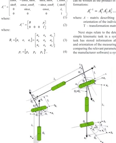
Metrological model is based on a kinematic description of the device, where as a basis for di -mensional analysis a description, in accordance with the Denavit-Harterberg (D-H) notation, was assumed. This notation is associated with each joint of local coordinate system (Fig. 1). Using a simple kinematics task, a string transformation of neighboring coordinate systems need to be speci -fied so as to determine the position and orienta -tion of the latter unit relative to the first unit of the device.
On the basis of the kinematic scheme the ma -trices of further transformations of coordinate systems need to be determined:
− − = − 1 0 0 0 cos sin 0 sin cos sin cos cos sin cos sin sin sin cos cos 1 i i i i i i i i i i i i i i i i i i i l l A λ α α θ θ α θ α θ θ θ α θ α θ where: = − 1 0 0 0
1 B p
Ai
i (2)
where:
[
]
= = iz iz iz iy iy iy ix ix ix i i i i a o n a o n a o n a o n B (3)
[
]
Tiz iy ix
i p p p
p = , (4)
where: Bi– orientation matrix,
pi– position matrix,
pix, piy, piz – coordinates of the position of suitable unit,
nix, niy, niż, oix, oiy, oiz, aix, aiy, aiz– coordi-nates of vector describing the rotation of the individual elements
The next step is to determine the so-called simple kinematics task. This is a static-geometric task, which can be regarded as the task of map -ping of description of the location of the device from the configuration coordinates space to the description of Cartesian coordinates space. The matrix of the position and orientation of system n relative to the system associated with the unit i
can be written as the product of successive trans-formations:
A
ii−1=
A
10A
21A
32...
A
ii−1 (5) where: A – matrix describing the location andorientation of the individual units, T – transformation matrix of matrix A. Next steps relate to the determination of the simple kinematic task in a symbolic way. This task has stored information about the position and orientation of the measuring stylus. Then (by comparing the relevant parameters with data from the manufacturer software) a system of equations
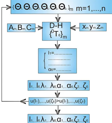
need to be built (6), which contains 28 unknowns describing the parameters needed to characterize the individual elements of the kinematic scheme, recorded in accordance with D-H notation, such as length of the units, as well as eccentrics, the angles between the axes, zero offset i.e. a differ -ence between a true indication of the encoder and the projection assumptions (Fig. 1). The algo -rithm of determination of the parameters is shown in Figure 2.
In order to obtain relevant data sets, length check in several settings in the measurement space should be measured. From the manufac -turer’s software, we read the configuration coor -dinates
θ
i (readings from the encoders), A, B, C (unit vectors describing the direction of the mea-suring stylus) and also cartesian coordinates x, y, z. Then we read the nominal data from the length check xn, yn, zn. After obtaining data from an ac-tual measuring device, as well as the check, we insert data into the equation (6):(
) (
) (
)
22 1 2 2 1 2 2 1
1 X S X S YS YS ZS Z S
D = − + − + −
where: D1– distance of two points on the length check,
X1S – model on the coordinate X of point 1 on the check determined from a simple task,
X2S – model on the coordinate X of point 2 on the check determined from a simple task,
Y1S – model on the coordinate Y of point 1 on the check determined from a simple task,
Y2S – model on the coordinate Y of point 2 on the check determined from a simple task,
Z1S – model on the coordinate Z of point 1 on the check determined from a simple task,
Z2S – model on the coordinate Z of point 2 on the check determined from a simple task. We obtain an accurate geometrical descrip-tion of each parameters. As, for the calculadescrip-tion, we have 28 variables, we have to build 28 equa -tions and each of the equa-tions will be built in an analogous way [1–7].
VALIDATION OF THE METROLOGICAL
MODEL OF CMA
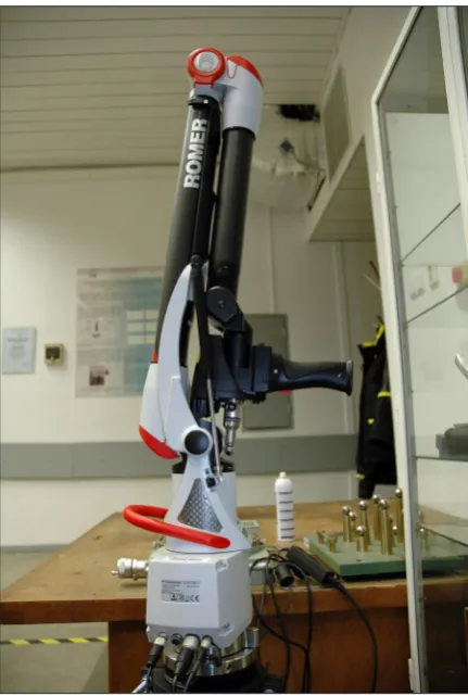
Measurements using multifeature check The measurements by coordinate measur -ing arm RA7320SI (Fig. 3a) were carried out in
Fig. 2. The algorithm for calculating the geometric accuracy of CMA
Where: Θm – readings from angular measurement systems; Am, Bm, Cm – unit vectors of direction of the measuring stylus; Xm, Ym, Zm – coordinates obtained from the manufacturer’s software (GDS or RDS); Xni, Yni, Zni – coordi-nates obtained from the length standard; lm – distance of axis zm−1 from axis zm measured along axis xm; αm – the angle between the axes zm−1 and zm measured about an axis xm; λm – distance of axis xm−1 from axis xm measured along axis zm-1; Dm – length read from the standard.
repeatability conditions using the multifeature check (Fig. 3b), developed and manufactured es -pecially in need of validation of coordinate mea -suring methods.
Validation covered in its scope the results, together with the calculated uncertainties, ob -tained by measuring three measurands: distance 100mm, and two diameters 25 mm and 35 mm of the multifeature check.
To validate metrological model, including specific results, the reference values should be chosen, called the limit values, that will come together to the established validation model. In this case, the reference values with calculated un -certainties are the values obtained from measure-ments of the same measurands of multifeature check but using validated multi-position method.
Validation model – the acceptance criterion of metrological model of CMA
The test of metrological compatibility is used to assess the significance of the difference be -tween two or more results which are traceable to the same reference. According to the [10–12] and definition of metrological compatibility, the set of results [x1, u(x1)], [x2, u(x2)], ….,[xn, u(xn)] for
the same measurand is metrological compatible if they fulfill the condition (7):
κ
≤ −
+
−
) ( ) ( )
,
( 2 ) ( )
( 2
2
R i R i R
i
R i
x u x u x x r x u x u
x x
where: xR, u(xR) – the reference values with the standard uncertainties,
r(xi , xR) – correlation coefficient between the variables xi , xR,
κ
– the threshold which conventional value is 2.If the condition is fulfilled, we can confirm the insignificant differences between the mea -sured values x1,…, xn in a view of the uncertain-ties u(x1) ,…, u(xn).
In this process of validation we have the pair (x1,u(x1)), (xR,u(xR)) where x1 is the mean value with its uncertainty u(x1) for the given measurand using metrological model of CMA and xR is the mean value with its uncertainty u(xR) for the giv-en measurand using the refergiv-ence multi-position method (Table 1, Table 2).
CONCLUSIONS
The developed metrological model of CMA was checked using the most closely appropriate model of validation. The comparison shows the insignificance of differences between the obtained results of both: metrological model of CMA and multi-position method. It evidently proves the correctness of the development of metrological model of CMA. The use of appropriate quality multifeature check also had a significant impact on the results. This check is now the most accu-rate measurement length check and its use for this validation process was most suitable.
Fig. 3b. Measurements using multifeature check
Fig 3a. Coordinate measuring arm RA7320SI
Table 1. The results for metrological model of CMA and validated multi-position method
Metrological model of CMA xi u(xi) Multi-position method xR u(xR)
25 mm 24.9725 0.0124 25 mm 24.9679 0.0127
35 mm 35.0215 0.0226 35 mm 35.0423 0.0164
100 mm 99.9707 0.0241 100 mm 99.9367 0.0198
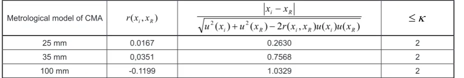
Table 2. The results of the metrological compatibility test
Metrological model of CMA r(xi,xR)
) ( ) ( ) , ( 2 ) ( )
( 2
2
R i R i R
i
R i
x u x u x x r x u x u
x x
− +
−
κ
≤
25 mm 0.0167 0.2630 2
35 mm 0,0351 0.7568 2
100 mm -0.1199 1.0329 2
Acknowledgments
Reported research were realized within confines of project financed by Polish Natio -nal Centre for Research and Development No: LIDER/024/559/L-4/12/NCBR/2013.
REFERENCES
1. Gąska A., Krawczyk M., Kupiec R., Ostrowska K., Gąska P., Sładek J.: Modeling of the residual ki
-nematic errors of Coordinate Measuring Machines using Laser Tracer system. International Journal of Advanced Manufacturing Technology, 2014, DOI: 10.1007/s00170-014-5836-1.
2. Ostrowska K., Szewczyk D., Sładek J.: Determina
-tion of operator’s impact on the measurement done using coordinate technique. Advances in Science and Technology Research Journal, 7(20), 2013, 16–21, DOI: 10.5604/20804075.1073045.
3. Ostrowska K., Gąska A., Sładek J.: Determining the uncertainty of measurement with the use of a Virtual Coordinate Measuring Arm. International Journal of Advanced Manufacturing Technology, 2013, DOI: 10.1007/s00170-013-5486.
4. Sładek J., Ostrowska K., Gąska A.: Modeling and identification of errors of coordinate measuring
arms with the use of a metrological model.
Mea-surement, 46, 2013, 667–679, DOI: 10.1016/j. measurement.2012.08.026.
5. Sładek J., Ostrowska K., Gacek K., Bryndza M.: Designation of operator impast on errors of measu
-rements realized by coordinate measuring arm. In: J. Sładek, W. Jakubiec (Eds.) Advances in Coordi
-nate Metrology, Bielsko-Biała 2010, 130–137. 6. Sładek J., Ostrowska K., Gąska A.: Wirtualne
współrzędnościowe ramie pomiarowe. Pomiary – Automatyka – Kontrola, 54(01), 2010.
7. Sładek J., Ostrowska K., Gąska A., Gacek K., Kmita A.: Model matematyczny opisu dokładności współrzędnościowych ramion pomiarowych. W: J. Gawlik (red.) Innowacyjne systemy produkcyjne. Monografia, 2009.
8. Sładek J., Ostrowska K., Gacek K.: Kinematic
metrological model of the coordinate measuring arm (MCMA). In: XIX World Congress Funda
-mental and Applied Metrology IMEKO, Lisbon, Portugal 2009.
9. Sładek J.: Dokładność pomiarów współrzędnościo-wych. Wydawnictwo Politechniki Krakowskiej, Kraków 2011.
10. Kacker R.N., Kessel R., Sommer K.D., Bian X.: Comparison of statistical consistency and metro
-logical compatibility. In: XIX World Congress Fundamental and Applied Metrology IMEKO, Lis
-bon, Portugal, 2009, 6–11.
11. Kacker R.N., Kessel R., Sommer K.D.: Assesing
differences between results determined according to
the Guide of Expression of Uncertainty in Measure
-ment. Journal of Research of the National Institute of Standards and Technology, 115, 2010, 453–459.
12. Kacker R.N., Kessel R., Sommer K.D.: Metrologi
-cal compatibility and statisti-cal consistency. In: