8.1
Chapter 8
Switching
3
Overview
• Networks are used to interconnect many devices.
• Switches are devices capable of creating temporary connections b/w two or more devices linked to the switch.
— Since the invention of the telephone, circuit switching has been the dominant technology for voice communications.
— Since 1970, packet switching has evolved substantially for digital data communications. It was designed to provide a more efficient facility than circuit switching for bursty data traffic.
• Two types of packet switching:
– Datagram (such as today’s Internet)
4
Switched Communications Networks
• Long distance transmission between stations (called “end devices”) is typically done over a network of
switching nodes.
• Switching nodes do not concern with content of data. Their purpose is to provide a switching facility that will move the data from node to node until they reach their destination (the end device).
• A collection of nodes and connections forms a communications network.
• In a switched communications network, data entering the network from a station are routed to the
8.5
Switching and TCP/IP Layer
•
Physical Layer – Circuit Switching
•
Datalink Layer – Packet (Virtual)
•
Network Layer – Packet (Virtual and Datagram)
•
Application Layer – Message
7
Circuit Switching
• Circuit switching:
— There is a dedicated communication path between two stations (end-to-end)
— The path is a connected sequence of links between network nodes. On each physical link, a logical channel is dedicated to the connection.
• Communication via circuit switching has three phases: — Circuit establishment (link by link)
• Routing & resource allocation (FDM or TDM)
— Data transfer
— Circuit disconnect
• Deallocate the dedicated resources
CIRCUIT-SWITCHED NETWORKS
• Before starting communication, the stations must make a reservation for the resources to be used during the communication, such that channel BW,switch buffers, switch processing time, and switch input/put ports, must remain dedicated during the entire duration of data
transfer until the teardown phase .
• The data are continuous flow.
9
Circuit Switching Properties
• Inefficiency
— Channel capacity is dedicated for the whole duration of a connection
— If no data, capacity is wasted
• Delay
— Long initial delay: circuit establishment takes time
— Low data delay: after the circuit establishment, information is transmitted at a fixed data rate with no delay other than the propagation delay. The delay at each node is negligible.
• Developed for voice traffic (public telephone network) but can also applied to data traffic.
— For voice connections, the resulting circuit will enjoy a high
percentage of utilization because most of the time one party or the other is talking.
CIRCUIT-SWITCHED NETWORKS
A circuit-switched network consists of a set of switches
connected by physical links. A connection between two
stations is a dedicated path made of one or more links.
However, each connection uses only one dedicated
channel on each link. Each link is normally divided into
n channels by using FDM or TDM.
Three Phases Efficiency
Delay
8.11
Three Phases
• Setup Phase:
• System A needs to request a connection to M that must be accepted by all the switches as well as M. This is
called Setup Phase.
• Data Transfer Phase:
• After the establishment of the dedicated circuit, two parties can transfer data.
• Teardown Phase:
• When parties need to disconnect, a signal is sent to each switch to release the resources.
CIRCUIT-SWITCHED NETWORKS
•
Efficiency :
•
It can be argued that circuit switch network is
not as efficient as the other 2 systems. Circuit
switching is dedicated for all users. These
resources are unavailable to other connections
during the active connection.
CIRCUIT-SWITCHED NETWORKS
•
Delay:
• The delay in this system is minimal. The data are not delayed at each switch, the resources are allocated for the duration of the connection.
• The total delay is due to time needed to create connection, transfer data and disconnect the circuit.
As a trivial example, let us use a circuit-switched network to connect eight telephones in a small area. Communication is through 4-kHz voice channels. We assume that each link uses FDM to connect a maximum of two voice channels. The bandwidth of each link is then 8 kHz. Figure 8.4 shows the situation. Telephone 1 is connected to telephone 7; 2 to 5; 3 to 8; and 4 to 6. Of course the situation may change when new connections are made. The switch controls the connections.
8.18
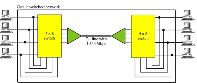
As another example, consider a circuit-switched network that connects computers in two remote offices of a private company. The offices are connected using a T-1 line leased from a communication service provider. There are two 4 × 8 (4 inputs and 8 outputs) switches in this network. For each switch, four output ports are folded into the input ports to allow communication between computers in the same office. Four other output ports allow communication between the two offices. Figure 8.5 shows the situation.
8.19
[image:19.720.22.691.147.431.2]Switching at the physical layer in the
traditional telephone network uses
the circuit-switching approach.
PACKET SWITCHING
•
In data communications, we need to send
messages from one end system to another. If
the message is going to pass through a
packet-switched network, it needs to be divided
into packets of fixed or variable size. The size of
the packet is determined by the network and
the governing protocol.
8.22
In a packet-switched network, there
is no resource reservation;
resources are allocated on demand.
Packet Switching
• In data communications, we need to send messages from one end system to another. If the message is going to pass through a packet-switched network, it needs to be divided into packets of fixed or variable size. The size of the packet is determined by the network and the governing protocol. • There is no resource allocation for the packet.
• The allocation is done on first come first serve basis. • No reserved BW on the link.
• The Packet must wait if there are other packets being processed.
24
Packet Switching Principles
•
Problem of circuit switching
— designed for voice service
— Resources dedicated to a particular call
— For data transmission, much of the time the connection is idle (say, web browsing)
— Data rate is fixed
• Both ends must operate at the same rate during the entire period of connection
25
Basic Operation
• Data are transmitted in short packets
— Typically at the order of 1000 bytes
— Longer messages are split into series of packets
— Each packet contains a portion of user data plus some control info
• Control info contains at least
— Routing (addressing) info, so as to be routed to the intended destination
— Recall the content of an IP header! • store and forward
26
Advantages of Packet Switching
• Line efficiency
— Single node-to-node link can be dynamically shared by many packets over time
— Packets are queued up and transmitted as fast as possible
• Data rate conversion
— Each station connects to the local node at its own speed
• In circuit-switching, a connection could be blocked if there lacks free resources. On a packet-switching network, even with heavy traffic, packets are still accepted, by delivery delay increases.
• Priorities can be used
27
Packet Switching Technique
•
A station breaks long message into packets
•
Packets are sent out to the network
sequentially, one at a time
•
How will the network handle this stream of
packets as it attempts to route them through
the network and deliver them to the intended
destination?
— Two approaches
• Datagram approach
28
Datagram
• Each packet is treated independently, with no reference to packets that have gone before.
— Each node chooses the next node on a packet’s path. • Packets can take any possible route.
• Packets may arrive at the receiver out of order. • Packets may go missing.
• It is up to the receiver to re-order packets and recover from missing packets.
• Example: Internet
Datagram
• Switches refer as Routers.
• Same message but different path to destination.
• Datagram sometime refer to as connectionless network. Means switch does not keep info about the connection state.
• Routing Table :
• There is no setup or teardown phases as circuit switching then how packet routed. In this each switch has routing table which is based on the destination address.
• The routing tables are dynamic and updated periodically.
• Destination address: Every packet in a datagram network carries a header that contains , among other info ,the destination address .
A switch in a datagram network uses a
routing table that is based on the
destination address.
The destination address in the header of
a packet in a datagram network
remains the same during the entire
journey of the packet.
Datagram
•
Efficiency :
•
Better than circuit switching.
•
Resources only be allocated when packet to be
transferred.
•
Delay:
•
Datagram has more delay than virtual switching.
•
Each packet may experience a wait at switch
before it forward.
35
8.36
VIRTUAL-CIRCUIT NETWORKS
A virtual-circuit network is a cross between a circuit-switched network and a datagram network. It has some characteristics of both.
Implemented at data link layer.
Addressing Three Phases Efficiency
Delay
37
Virtual Circuit
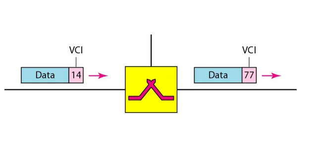
• In virtual circuit, a preplanned route is established before any packets are sent, then all packets follow the same route.
• Each packet contains a virtual circuit identifier instead of destination address, and each node on the pre-established route knows where to forward such packets.
— The node need not make a routing decision for each packet.
8.38
VIRTUAL-CIRCUIT NETWORKS
• In virtual networks , two types of addressing are involved.
• Global Addressing: A source and a destination needs to have a global address. It is unique for international network.
• Virtual Circuit Identifier (VCI). Or Label is a small number that has only switch scope, it is used by the frames b/w 2
switches.
• VCI in a data frame changes from one switch to another.
8.40
VIRTUAL-CIRCUIT NETWORKS
Three Phases: Like circuit switched network, a source and destination need to go through three phases. Setup , data transfer and teardown.
Setup : The source and destination use their global addresses to help switches make table entries for the connection.
Teardown: The source and destination inform the switches to delete the corresponding entries.
Data Transfer: transfer of data. Setup Phase : has two Step
Setup request: frame sent from source to destination.
8.42
8.43
45
Virtual
Circuit
A route between stations is set up prior to data transfer.
All the data packets then follow the same route.
Comparison of communication
8.47
8-4 STRUCTURE OF A SWITCH
We use switches in circuit-switched and packet-switched
networks. In this section, we discuss the structures of
the switches used in each type of network.
Structure of Circuit Switches
Space Division and Time Division Switches Structure of Packet Switches
STRUCTURE OF A SWITCH
•
Space division switch : separated from one
another spatially.
•
Crossbar Switch:
•
Multistage Switch:
nxm
8.50
Multistage switch
•
Single switch has limitation of crossbar switch.
•
In a single crossbar switch, only one row or
column (one path) active.
•
In multistage switch, each crosspoint in the
middle stage can be addressed by the multiple
crosspoint in the first or third stage.
•
K= Number of Crossbar in the middle stage
•
N= Input lines
•
n= Lines
8.52
In a three-stage switch, the total
number of crosspoints is
2kN + k(N/n)
28.53
Design a three-stage, 200 × 200 switch (N = 200) with
k = 4 and n = 20.
Solution
In the first stage we have N/n or 10 crossbars, each of size
20 × 4. In the second stage, we have 4 crossbars, each of
size 10 × 10. In the third stage, we have 10 crossbars,
each of size 4 × 20. The total number of crosspoints is
2kN + k(N/n)
2, or
2000
crosspoints. This is 5 percent of
the number of crosspoints in a single-stage switch (200 ×
200 = 40,000).
Multistage Switch
• Multistage Switch : drawback is blocking, as middle stage crosspoint shared by all crossbar.
• In single stage no blocking occur as every combination of input and output has its own crosspoint.
• The whole idea of multistage switching is to share the crosspoint in the middle stage crossbars.
• Clos investigated the condition of nonblocking in
multistage switches and came up with the formula. In a nonblocking switch, the number of middle stage
switches must be at least 2n-1.
8.55
According to the Clos criterion:
n = (N/2)
1/2k > 2n – 1
Crosspoints ≥
4N [(2N)
1/2– 1]
8.56
Redesign the previous three-stage, 200 × 200 switch,
using the Clos criteria with a minimum number of
crosspoints.
Solution
We let n = (200/2)
1/2, or n = 10. We calculate k = 2n − 1 =
19. In the first stage, we have 200/10, or 20, crossbars,
each with 10 × 19 crosspoints. In the second stage, we
have 19 crossbars, each with 10 × 10 crosspoints. In the
third stage, we have 20 crossbars each with 19 × 10
crosspoints. The total number of crosspoints is 20(10 ×
19) + 19(10 × 10) + 20(19 ×10) =
9500
.
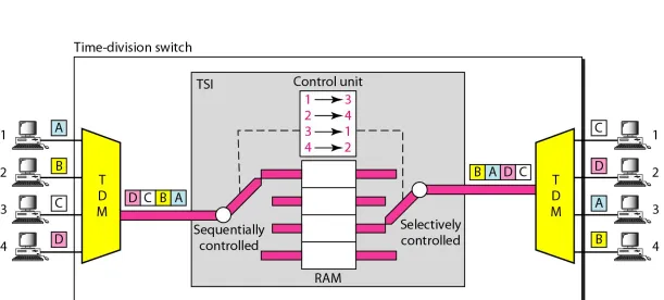
Time Division Switch
• Todays Telephone companies using TD switching or the combination of TD and SD switching.
• It uses TDM inside a switch.
• The most popular technology is called Time Slot Interchange (TSI).
• TSI consist of RAM with several memory locations. The size of each location is the same as the size of single time slot.
• The RAM is fills up with incoming data from time slot in the order received. Slots are then sent out in an order based on the decisions of a control unit.
8.58
Time and Space Division Switch Combine
(TST Switch)
•
SDS : Adv : It is instantaneous
•
Disadv: Number of Xpoints required
•
TDS: Adv : Needs no xpoints
•
Disadv: Each connection creats delay. Each time
RAM stored and then retrieved.
•
Combine both
8.60
Time-space-time switch (TST)
•
2 Time Stage Switch
•
1 Space Stage Switch
•
12 Inputs and 12 outputs
•
The result is average time delay is one third as
compare to using one TSI to handle all 12
inputs.
Structure of Packet
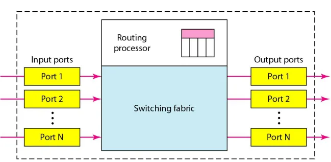
•
Packet Switch has 4 components,
•
Input Port
•
Output Port
•
Routing Processor
•
Switching Fabric
8.63
Packet switch components
•
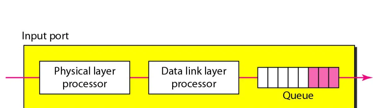
Input Ports: An I/P port performs the physical
and data link functions of the packet switch.
•
Packet decapsulated from the frame
•
Errors are detected and corrected.
•
Bits are contructed from the received signal.
•
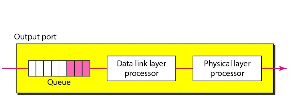
Output Port:
•
Encapsulated the packet in a frame
8.65
8.66
Packet switch components
•
Routing Processor:
perform the functions of the Network layer.• The destination address is used to find the address of the next hop, at the same time the output port number from which the packet sent.
• Routing processor search the routing table.
•
Switching Fabrics:
• Is the most difficult task in a packet switch is to move the packet from the i/p queue to the o/p queue.
• The speed depends upon the size of the queues and overall delay in packet delivery.
Switching Fabrics:
•
In past memory of computers was used as the
switching fabrics.
•
Today packet switches are specialized
mechanism that use a variety of switching
fabrics.
•
Crossbar Switch
•
Banyan Switch
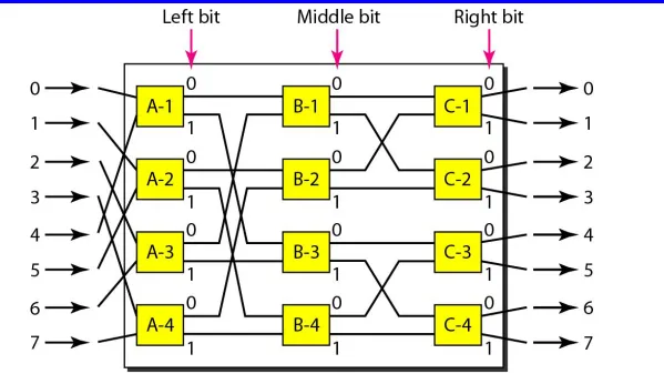
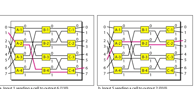
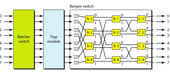
Banyan Switch
• More realistic approach than the crossbar switch.
• As named after the Banyan Tree.
• Is a multistage switch with micro stages at each stage that route the packets based on the o/p port
represented the binary string.
• The first stage routes the packet based on the higher order bit of the binary string. The second stage routes the packet based on the second high order bit and so on.
• Log 2 n Stages
• n/2 mircoswtiches
• Example: n=8 (8 i/p and o/p)
8.70
[image:70.720.52.651.102.439.2]8.71
Batcher-banyan switch
• To overcome the problem of possible internal collision if 2 packets will go at same output from different inputs.
• Batcher switch come before the banyan switch and sorts the incoming packets according to their final destination.
• TRAP module place in b/w that prevent the duplicate packet. Only one packet for each destination is allowed.
8.73