Reflection of Light
Light
1. What is Light?
Learning Outcomes
In this section, you’ll be able to:
Understand how light travels and how we are able to see. Understand the terms used for reflection:
Normal
Angle of incidence Angle of reflection
1. What is Light?
Light is a form of
energy
.
Our eyes detect light in a range of colours – red,
orange, yellow, green, blue, indigo and violet.
1. What is Light?
How does light travel?
1. What is Light?
What are luminous and non-luminous objects?
Luminous objects are objects which
give off
light of
their own
e.g. Lighted lamp, images on a TV screen
Non-luminous objects are objects that do not give off
1. What is Light?
Blind Creatures
Mexican Tetra or
Blind Cave Fish
Blind Albino Cave Crab
The paths along which the light travels are called rays.
A beam of light consists of a bundle of light rays
A light ray is represented by an arrow, pointing in the direction that the light is travelling
1. What is Light?
Key Ideas
1.
Light is a form of
energy
.
1. What is Light?
Question:
1. What is Light?
Answer:
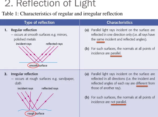
2. Reflection of Light
Laws of Reflection:
1. 1st Law of Reflection
The incident ray, the reflected ray and the normal to the reflecting surface all lie in the same plane.
2. 2nd Law of Reflection
The angle of incidence is equal to the angle of
reflection
2. Reflection of Light
Question:
Draw a diagram to show clearly the incident ray, normal, reflected ray, angle of incidence and the angle of reflection. What is the relationship between angle of incidence and angle of reflection.
incident ray
2. Reflection of Light
Question:
1. Draw a diagram to show clearly the incident ray, normal, reflected
ray, angle of incidence and the angle of reflection. What is the relationship between angle of incidence and angle of reflection. Answer:
i
r
incident ray normal mirror2. Reflection of Light
2. Reflection of Light
Characteristics of the image formed by a
plane
mirror:
1.The image is of the
same size
as the object.
2.
It undergoes
lateral
inversion.
3.It is
upright
.
4.
It is
virtual
.
Lateral Inversion
Reflection of Light
Light
3. Constructing Ray Diagrams
Learning Outcome
In this section, you’ll be able to:
Apply the principle of reflection in constructing ray
3. Constructing Ray Diagrams
Ray Diagrams for plane mirrors
3. Constructing Ray Diagrams
Step 1: Image distance from mirror = object distancefrom mirror
i) Measure accurately the perpendicular distance between object O and the
mirror surface.
3. Constructing Ray Diagrams
Step 2: Draw the light rays from the image to the eye
i) Use dotted lines behind the mirror
3. Constructing Ray Diagrams
Step 3: Draw the incident rays from object O to the point of incidence on the mirror surface.
4. Applications of Mirrors
1. Optical testing
Plane mirrors are used to
reduce the distance
4. Applications of Mirrors
2. Mirrors at blind corners
Such mirrors can be installed in shops to allow
shopkeepers to watch out for shoplifters
Can also be installed at blind corners to allow drivers to
make a turn safely
4. Applications of Mirrors
3. Instrument Scales
By placing a mirror below the pointer of a scale, parallax error can be avoided when taking readings. This is done by ensuring that the image of the pointer is in line with the pointer itself.
4. Applications of Mirrors
4. Periscope
Using two plane mirrors inclined at 45°, a periscope allows
4. Applications of Mirrors
5. Other uses
5. Key ideas
1.
Ray diagrams are used to
locate the position
of a
mirror image.
Exercise
1. Figure below shows an extended object. Using ray diagrams, locate the image of the arrow. Describe the image formed.
Exercise
1. Figure below shows an extended object. Using ray diagrams, locate the image of the arrow. Describe the image formed. Answer:
2. An optician’s eye chart is fixed 0.5 m behind the eyes of a patient looking into a mirror placed 3.0 m in front of him. Find the
distance of the chart as seen by his eyes.
2. An optician’s eye chart is fixed 0.5 m behind the eyes of a patient looking into a mirror placed 3.0 m in front of him. Find the
distance of the chart as seen by his eyes.
Answer:
The distance of the eye chart is 3.5 m from the mirror.
Hence the image of the eye chart is 3.5 m behind the mirror. Therefore chart’s image is 6.5 m away from the patient’s eyes.
mirror 3.0 m Patient’s Chart
Chart
In the absence of mirror,
need longer space
Refraction
LESSON-3
Learning Outcomes
In this section, you’ll be able to:
Understand the terms used for refraction:
Normal Angle of incidence Angle of refraction
Light can travel through transparent materials such as glass, water or plastic. Figure below shows a light ray traveling from air into glass, and then into air again.
Refraction
What causes refraction?
Light travels at different speed in different media.
For example, in air its speed is 3.0 × 10⁸ m s-1, while in glass it
is 2.0 × 10⁸ m s-1.
Refractive Index,
n
speed of light in vacuum or air Refractive index of medium =
speed of light in medium
c
n =
v
For light passing from air or vacuum into a medium, then
(a) State the speed of light in air.
(b) Calculate the speed of light in a glass block which has a refractive index of 1.53.
(a) Speed of light in air = 3 x 10⁸ m/s
speed of light in vacuum or air Refractive index of medium =
speed of light in medium (b)
1.53 = 3 x 10⁸ / v
v = 3 x 10⁸ / 1.53
Misperception of Depth (Apparent depth)
The effect of refraction can make the depth seems shallower
Draw a diagram to show how the eye sees a coin at the bottom of a bucket of water.
Draw a diagram to show how the eye sees a coin at the bottom of a bucket of water.
water
air
Exercise 2
Laws of Refraction
1.
The
incident
ray, the
normal
and the
refracted
ray all
lie in the
same plane
.
2.
For two particular media, the
ratio
of the
sine
of the
angle of incidence
to the
sine
of the
angle of
refraction
is a
constant
, i.e.
Snell’s Law
n
isin i = n
rsin r
where ni = refractive index of medium i
nr = refractive index of medium r
i
r
incident ray
n
iRefractive index
Glass (nglass = 1.50) a higher refractive index than water (nwater= 1.33). When a light ray enters glass, it will bend towards the normal more than compared to when it enters water.
air
i
air
i
At what angle of incidence in air will light pass through another transparent medium without being refracted?
Answer:
When the angle of incidence,
i = 0° from the normal, the
air
Key Ideas
1. Refraction occurs because the speed of light changes when travelling through different optical media.
2. The two laws of refraction are:
a. The incident ray, the normal and the refracted ray all lie in the same plane.
b. For two particular media, sin i
3. The refractive index n of a transparent medium is
c
n =
v
where c is the speed of light in vacuum or air,
v is the speed of light in the medium
4.
sin i
= n
sin r
where in air or vacuumi is the angle of incidence of lightTotal Internal Reflection
Light
6. Total Internal Reflection
Learning Outcomes
In this section, you’ll be able to:
Define the terms critical angle and total internal
reflection.
Identify the main ideas in total internal reflection and
apply them to the use of optical fibres in
6. Total Internal Reflection
Total internal reflection can occur when light passes
from an
optically denser
to a
less dense
6. Total Internal Reflection
What is the critical angle?
1. When a ray of light is directed perpendicularly through the semicircular glass block, the light ray will pass through
6. Total Internal Reflection
What is the critical angle?
6. Total Internal Reflection
What is the critical angle?
3. As the incident angle is increased, the refracted ray is seen to bend further away from the normal. It comes a point when the refracted
6. Total Internal Reflection
What happens if the angle of incidence is greater than the critical angle?
6. Total Internal Reflection
Total Internal Reflection takes place only when
1. a ray of light travels from an optical denser medium to a
less dense medium
6. Total Internal Reflection
How to determine the critical angle of a medium?
When the angle of incidence is at the critical angle c, then the angle of refraction r = 90o. Since the light ray is from the medium into
air, we use the principle of reversibility. Hence
o
sin 90 1
n = =
sin c sin c
6. Total Internal Reflection
Key Ideas
1.
Total internal reflection takes place only when light
travels from optical
denser
to a
less dense
medium.
2.
The
critical angle
c
is the
angle of incidence
in
the optically
denser
medium at which the
angle of
refraction
in the
less dense
medium is
90
°
.
Applications of total internal reflection
Applications of total internal reflection
Optical fibres are made up of thin glass or plastic fibres
that transmit light over long distances through total
internal reflection, even when bent. An optical fibre has a
core of a high refractive index, coated with another
6. Total Internal Reflection
Test Yourself
Determine the critical angle of a glass prism with a refractive index of 1.9.
Answer:
Given refractive index, n = 1.9
Applying the equation 1
sin c = n
1
Thin Converging Lens
7. Thin Converging Lens
Learning Outcomes:
In this section, you’ll be able to:
Describe the action of a thin lens (converging and diverging)
on a beam of light.
Define the term
focal length
for a converging lens.
What is a lens?
A lens is a piece of
clear plastic or glass
with
curved
surfaces.
How does a lens refract light?
A lens can be thought of as a set of blocks and prisms.
Types of Lenses
–
Converging and Diverging
For converging lenses, parallel light rays are brought to
focus
at a point
. (Converge)
For diverging lenses, parallel light rays tend to be
spread out
.
(Diverge)
Thin converging lens and its main features
1. Optical centre C – Midpoint between the lens surfaces on its principal axis.
2. Principal axis – The horizontal line passing symmetrically through C.
3. Focal point F – All parallel rays to the principal axis converge at the focal point F.
4. Focal length, f – The distance
Tracing path of light through a thin converging
lens
3 definite paths for light rays passing through a thin converging lens:
Key Ideas
1. Lenses are used to converge and diverge a beam of light.
2. The main features of a thin converging lens are:
Optical centre C
Focal length f
Focal point F
8. Ray Diagram for Lenses
How to locate the position of an image?
3 steps to locate the image:
Step 1: Set up the lens and the ray diagram. Step 2: Placing the object.
Step 1: Set up the lens and the ray diagram
i. Draw principal axis ii. Draw the lens
iii. Mark optical centre C iv. Mark the focal point F
Step 2: Placing the object.
i. Place the object O to the left of the lens. ii. Mark the object distance as u.
Step 3: Trace the light rays and draw the image.
i. Draw 2 of the 3 definite paths e.g. Path 1 and 2.
ii. The point where the two light paths intersect is the position of the image.
Virtual image formed by a converging lens
When the object O is placed near to the lens such that the object distance u is less that the focal length f, then a virtual image is formed. A virtual image cannot be captured on screen.
9. Applications of Converging Lenses
Converging Lenses are used in many optical instruments:
Magnifying glass LCD projector Camera
Magnifying glass
When the object is placed such that u < f, image is magnified,
virtual and upright.
LCD Projector
Camera Lens
For the camera lens, the image is diminished, real and inverted.
Visual Correction for Long-sightedness
People with long-sightedness are unable to focus a clear image of near objects on the retina. Spectacles with converging lenses can partially
Key Ideas
1. Ray diagrams can be constructed to locate the position and type
of image formed by a thin converging lens.
2. Light paths using Path 1 and Path 2 to construct the ray diagram. 3. A real and inverted image is formed when object distance u >
focal length f. The image is formed on the other side of the lens.
4. A virtual and upright image is formed when the object distance u
Self-Test
How far from a thin converging lens must an object be placed
to produce a magnified image?
Answer:
1.When object distance u < focal length f, the image is magnified,
Recall
Trigo. Ratios:
sin
= opp. side / hypot. = b/c
cos
= adj. side / hypot. = a/c