Design and Implementation of Digital Temperature Controller
Yang LIU
School of Information Science & Electric Engineering, Shandong Jiaotong University, China
I.
INTRODUCTION
Since the 1970s, due to the need for industrial process control, especially the rapid development of microelectronics technology and computer technology and the development of automatic control theory and design method, foreign temperature control system is developing rapidly, and in the intelligent, adaptive, parameter self-tuning and other aspects of significant achievements. In this regard, to Japan, the United States, Germany, Sweden and other countries leading technology, have produced a number of commercial, excellent performance of the temperature controller and instrumentation, and widely used in various industries [1-3]. They mainly have the following characteristics:
(1) Adapt to large inertia, large delay and other complex temperature control system control.
(2) Can be adapted to the controlled system of mathematical model difficult to establish the control of the temperature control system.
(3) Can be adapted to the controlled system process complex, parameter time-varying temperature control system control.
(4) These temperature control systems generally adopt adaptive control, self-tuning control, fuzzy control, artificial intelligence and other theories and computer technology, the use of advanced algorithms to adapt to a wide range. (5) The thermostat has the parameter self-tuning function. With the help of computer software technology, the thermostat has the control object control parameters and characteristics of the automatic tuning function. And some also have a self-learning function, according to historical experience and control of the object changes, automatically adjust the relevant control parameters to ensure the optimization of control results.
(6) The temperature control system has the characteristics of high control precision, strong anti-interference ability and good robustness. At present, foreign temperature control systems and instruments are moving towards high precision, intelligent, miniaturization and other aspects of rapid development.
Although the application of temperature control system in all walks of life in China has been very wide, but from the domestic production of temperature controller, the overall level of development is still not high, with foreign Japan, the United States, Germany, compared to advanced countries, still have a larger difference. At present, China's overall technical level in this area is still in the 20th century, the late 80s level, mature products mainly to "point" control and conventional PID controller-based, can only adapt to the general temperature system control, difficult to control lag, Complex, time - varying temperature system.And adapt to the higher control of the occasion of the intelligent, adaptive control instruments, the domestic technology is not very mature, the formation of commercial and widely used control instruments are less.
At present, China's temperature and other control instrument industry and foreign gap mainly in the following
Abstract:
This paper takes AT89C52 microcontroller as the core, and using the United States Dallas Semiconductor DS18820 line digital temperature sensor for the temperature measurement part. Using the LCD1602 display to show measured and controlled temperature. The system uses the C programming language to complete the measurement function call. With it, users can set the upper and lower limits of temperature. When the temperature goes beyond the upper or lower limit, it can give an alarm automatically. To solve the complicated circuit control of the temperature measurement problems, the alarm further improved on the basis of traditional circuit control.(2) Commercial products to PID controller-based, less intelligent instruments, this gap with foreign large. At present, the domestic enterprises complex and high precision requirements of the temperature control system are mostly imported temperature control instruments.
(3) Instrument control with key technologies, related algorithms and control software research abroad lag. For example: in the instrument control parameters of the self-tuning, foreign countries have more mature products, but due to foreign technology and the development of China's development lag, has not developed a reliable self-set software, control parameters mostly by manual experience And on-site commissioning to determine. These gaps are what we must strive to overcome.
With the development of China's economy and accession to the WTO, our government and enterprises attach great importance to this, the relevant enterprise resources were reorganized, have established a number of countries, enterprises R & D center, and through joint ventures, technical cooperation, A number of joint ventures, cooperation and wholly-owned enterprises, so I with the temperature and other instruments industry has been rapid development.
II.
SYSTEM
HARDWARE
DESIGN
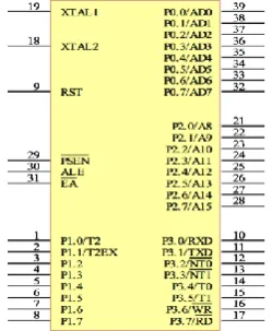
1. AT89C52 microcontroller overview and pin description
The AT89C52 and AT89C52 microcontrollers in the AT89 series of microcontrollers produced by ATMEL are a new low power, high performance 8-bit CMOS microcontrollers that are fully compatible with the industry standard MCS-51 instruction series and pins. Has a super three-level encryption function, the on-chip lightning memory (Flash Memory) programming and erase completely power to achieve, the data is not volatile, programming / erase fast [8,9].
AT89C52 main features are:
Internal program memory for the erasure Programmable read-only memory EEPROM, 8KB capacity, internal data memory capacity 256 bytes, the maximum addressing space 64KB.
Three 16-bit timer / counters.
Two I / O lines can be used as full-duplex serial port, there are four ways to work, can be programmed to set.
The internal ROM has four general working register areas, a total of 32 general-purpose registers to accommodate a variety of interrupt or subroutine nesting situation.
6 interrupt sources, divided into two interrupt priority levels, each interrupt source priority is programmable.
There is a Boolean processor consisting of direct bit-addressable, which contains a subset of instructions in the instruction system that are used to perform various Boolean processing on the Boolean processor, especially for control purposes and to solve logical problems.
AT89C52 state cycle by the crystal oscillator 2 obtained after the frequency, as the basic working time unit of the chip, in the use of 12MHz crystal, AT89C52 state cycle (2/12) * 10-6 = 167ns.
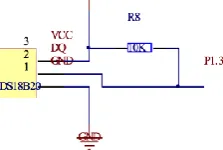
2. Temperature measurement circuit module
As shown in Figure 2, the temperature measurement module, because the DS18B20 chip temperature measurement is digital integrated temperature measurement, its external circuit is very simple, only three pins, one connected to the power supply VCC, one ground, the other one Then AT89C52 P1.3 port.
CPU access to the DS18B20 process is: first DS18B20 initialization, and then ROM operation command, and finally to the memory operation, data operation. Each step of the DS18B20 follows a strict working sequence and communication protocol. Such as the host control DS18B20 to complete the process of temperature conversion, according to DS18B20 communication protocol, to be three steps: every time before and after the DS18B20 must be reset, reset a successful write a ROM instruction, and finally send RAM instructions, so as to The DS18B20 performs a predetermined operation.
Fig. 2 Temperature measurement circuit module
3. Temperature control circuit module
Temperature control circuit design work process: the actual measurement of the temperature and set the upper and lower limits to compare, to control the P1.4, P1.5 port high and low levels.
Alarm circuit consists of two main components, LS1 alarm device and Q1 three-level tube. If the signal from the microcontroller P1.4 end of the transistor base and emitter conduction, that is, when the current through, then from VCC to LS1 to the collector will have a current through. This will let the alarm device alarm signal, if the signal from the microcontroller P1.4 side of the transistor base and emitter is not conduction, no current through, LS1 no sound.
In the control circuit, if the actual measured value exceeds the upper and lower limits of the set value, the P1.5 pin is high, so that the LED does not emit light, the phototransistor remains high impedance state, the relay will not work, the motor and the bulb remain Conduction, equivalent to the heater began to heat or the equivalent of fan cooling, light. And in the normal temperature, the microcontroller control P1.5 feet into a low level, light-emitting diode conduction light, phototransistor by the impact of light conduction, and then work on the relay, the solenoid will be single-pole double-throw switch to the left, so that the motor and The lamp stops working at the same time, which is equivalent to powering the heater or the fan [10-12].
III.
S
OFTWARED
ESIGN OFT
EMPERATUREC
ONTROLS
YSTEM1. The main program of the system
The main program is the system monitoring program, in the process of running the program must be initialized, including the keyboard program, interrupt procedures, LCD display program and the initialization of the various control ports. The system enters the temperature measurement program after initialization, real-time measurement of the current temperature and through the display circuit on the LCD display. Program to enter the keyboard to re-set the temperature of the upper and lower limits, according to the hardware design to complete the temperature control, the appendix gives the system initialization source.
2. Temperature acquisition program design
3. Software anti-jamming measures
The key is a mechanical switch, when the button is pressed, the switch is closed; when the button is released, the switch is disconnected. One of its characteristics is its jitter, which is determined by the mechanical properties of the keys, jitter time is generally about 10ms-20ms.
There are two specific measures for the key to shake: First, with a hardware circuit to achieve, that is, with RC filter circuit filter jitter. The other is to use software delay method to solve, that is, the use of software delay to avoid the button press and lift when there are jitter period, so as to avoid detection of interference signals. This article is used in software delay shaking method. The source code for the delay program is given in the appendix, and the delay program is also called by the other modules as a common function module.
IV.
SYSTEM
DEBUGGING
AND
SIMULATION
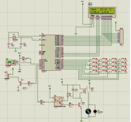
After writing the program in the Keil software, compile the .Hex file, the microcontroller can execute the .ex file. In the Proteus software, to the microcontroller to load the generated. Hex file, press the run button, the system began to simulate. System simulation screenshots as shown in Figure 3.
Figure 3 for the ambient temperature does not exceed the set temperature when the upper and lower limits of the simulation screenshot, you can see from the figure at this point the ambient temperature value of 27.31 ℃, set the upper limit temperature of 50 ℃, the lower limit temperature of 0 ℃. Relay work, the single-pole double-throw switch to the left, the heater or radiator to stop working [13-15].
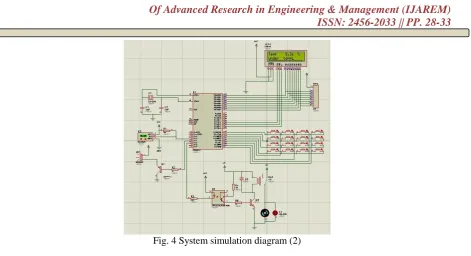
Figure 4 for the ambient temperature exceeds the lower limit of the set temperature when the simulation screenshot, you can see from the figure at this time the ambient temperature value of 5.31 ℃, through the keyboard to reset the lower limit temperature of 10 ℃, significantly lower than the lower limit, LCD second Line shows "Under tempL". At this time, P1.5 feet are high, the relay will not work, the motor and the lamp to maintain conduction, the equivalent of heating the heater began, the indicator light. While P1.4 feet are also high, the alarm system began to alarm.
Similarly, when the ambient temperature is higher than the set temperature limit, the second line of the LCD shows "Over temp H", the motor and the bulb remain on, which is equivalent to the heat sink, the indicator light is on, and the alarm system starts to alarm. There is no picture here.
Fig. 4 System simulation diagram (2)
V.
CONCLUSION
The research system, using the most advanced intelligent digital temperature sensor DSl8820 and with the microcontroller 89C52 together constitute an intelligent temperature control system. Now on the market, many types of temperature sensors, generally as mentioned above, there are two integrated sensor and digital sensors, the reason why the use of digital single-bus temperature sensor DSl8B20, because it is one of the latest temperature devices, integrated temperature measurement , A / D conversion in one, with a single bus structure, digital output, directly with the computer interface, etc., can use it to form a single temperature measurement device can also be used to form a multi-channel temperature measurement device.
This temperature controller, although the circuit is simple, small size, but due to the use of digital temperature sensor, the measurement is relatively accurate, with a certain practical value in the circuit design, but also increased the keyboard input module, the upper and lower limits set with the circuit Alarm module, as long as by changing the upper and lower limits of the set temperature, the measured actual temperature exceeds the existing temperature, it will issue an alarm, and the corresponding control of the flexible design.
REFERENCES
[1] Kang Y J, Yang S. Integrated microfluidic viscometer equipped with fluid temperature controller for measurement of viscosity in complex fluids[J]. Microfluidics and nanofluidics, 2013, 14(3-4): 657-668. [2] Engstrom J R, Weinberg W H. Design and construction of a digital temperature controller for use in
surface studies[J]. Review of scientific instruments, 1984, 55(3): 404-409.
[3] Muha R J, Gates S M, Yates Jr J T, et al. Digital temperature programmer for isothermal and thermal desorption measurements[J]. Review of scientific instruments, 1985, 56(4): 613-616.
[4] Bhatnagar R. Multipoint digital temperature controller: U.S. Patent 6,336,593[P]. 2002-1-8.
[5] Singla S K, Singh V. Design of a microcontroller based temperature and humidity controller for infant incubator[J]. Journal of Medical Imaging and Health Informatics, 2015, 5(4): 704-708.
[6] Singhala P, Shah D, Patel B. Temperature control using fuzzy logic[J]. arXiv preprint arXiv:1402.3654, 2014.
[7] Dugay J, Giménez‐ Marqués M, Kozlova T, et al. Spin Switching in Electronic Devices Based on 2D Assemblies of Spin-Crossover Nanoparticles[J]. Advanced Materials, 2015, 27(7): 1288-1293.
[11] Mosconi E, Quarti C, Ivanovska T, et al. Structural and electronic properties of organo-halide lead perovskites: a combined IR-spectroscopy and ab initio molecular dynamics investigation[J]. Physical
Chemistry Chemical Physics, 2014, 16(30): 16137-16144.
[12] Blaeser A, Duarte Campos D F, Weber M, et al. Biofabrication under fluorocarbon: a novel freeform fabrication technique to generate high aspect ratio tissue-engineered constructs[J]. BioResearch open access, 2013, 2(5): 374-384.
[13] Ho D H, Sun Q, Kim S Y, et al. Stretchable and multimodal all graphene electronic skin[J]. Advanced Materials, 2016.
[14] Lam S S, Mahari W A W, Jusoh A, et al. Pyrolysis using microwave absorbents as reaction bed: An improved approach to transform used frying oil into biofuel product with desirable properties[J]. Journal of Cleaner Production, 2017, 147: 263-272.