164
Reduction of Harmonics & Improve Efficiency Using Multi Pulse
Converter
Hemant Dhanuk1,Prashant Singh2,Saurabh Gupta3
Department of Electrical and Electronics Engineering
Technocrats Institute of Technology & Science, Bhopal
[email protected], [email protected], [email protected]
Abstract: Due to switching of power electronics
devices harmonic are induced in the line. These
harmonic induced bad effect on transmission line
such as dipping of voltage, it also minimized the
efficiency and life of equipments. In this study
presents line commutated controlled multipulse
converters for solving the harmonic problem. The
effect of increasing the number of pulses on the
performance of AC to DC converters has been
analyzed. For performance comparison major
factors considered are the ripple percentage, form
factor and the total harmonic distortion (THD). The
effects of load variation on multi-pulse AC to DC
converters have also been investigated. This work
presented the comparative study of 24, 36, 48 and
60 pulse converters.
Keywords Multipulse converter, Harmonics
distortion, Ripple counters.
1. Introduction
Three-phase controlled rectifiers have a wide range of applications, to large high voltage direct current (HVDC) transmission systems from small rectifiers.
They are used for electrochemical processes, wide range of motor drives, controlled power supplies, traction equipment and other applications. The commutation process can be classified into two important categories namely: Line-commutated controlled rectifiers and Force-commutated pulse width modulated rectifiers. There are several techniques primarily adopted for the mitigation of
harmonics in a 3-phase converter and multi-pulse
converters fall in the same category of remedial
measures. Multi pulse converters are the most
fundamental solution for harmonic problem in a
three-phase converter system. With the
advancements in technology advances these
converters and other power electronic devices with
integrated magnetic featuring high input power
quality and better performance would be required
by many industrial, commercial applications, power
supplies. The effect of increasing the number of
pulses of AC to DC converters directly alters its
performance parameters like ripple percentage,
165 Multipulse converters are converters providing more than six pulses of DC voltage per cycle from AC input or the converter having more steps in AC input current than that of six pulse bridge rectifier supply current. Phase shifting transformers are used to derive multipulse phase supply from three-phase AC mains using different combinations of transformer windings such as star, delta, zigzag, polygon, fork etc. In this thesis we use zigzag transformer. The phase-shifting transformers play a key role in the multi-pulse rectifier's performance. Jiaopu et.al [1] discussed commonly used basic connections of phase-shifting transformer, such as Scott, polygon, star/delta, extended-delta and zigzag and gave the analyses and comparisons between them. Focusing on 12-pulse phase-shifting transformers, the research highlighted possible strategies from basic connections to 12-pulse phase-shifting transformers which illustrate the evolution and its basic principles which may be extended to higher pulse converters. Singh et.al [3] analyzed the performance of multi-pulse electronic load controller for isolated asynchronous generator, as load controller conventional electronic based six pulse uncontrolled rectifier contains large content of harmonics. A comparative study of three phase controlled multi pulse converters was presented by [4] for biomass, gas turbine, wind system based power plant, diesel, hydro, , and incorporated input current shaping of controlled rectifier using multi-pulse current shaping concept. The author Xigeng et.al [6] introduced the realization of phase-shifting
of the multi-pulse converter transformer and the
method for calculating stretch phase-shifting angle,
triangle voltage and the 7 number of windings and
analyzed the simulation for the 30-pluse
rectification system based on this transformer.
Arvindan et.al [7] proposed two 24-pulse rectifier
topologies based on phase shifting using
conventional magnetic over PSCAD environment.
2. Controlled Rectifiers
There are two types of conversion techniques , one
is uncontrolled in which diodes are implemented
and other is controlled in which thyristors are
implemented respectively [8].The performance
improvement is achieved for total harmonics
distortion (THD) in input current, DC voltage
ripples and form factor. Three-phase controlled
rectifiers have a wide range of applications, to large
high voltage direct current (HVDC) transmission
systems from small rectifiers. They are used for
electrochemical processes, wide range of motor
drives, controlled power supplies, traction
equipment and other applications.
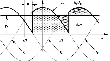
2.1Three-phase Half-wave Rectifier
To control the load voltage, the half-wave rectifier uses three common-cathode thyristor arrangements. The thyristor will conduct (ON state), when the anode-to-cathode voltage VAK is positive and a firing
166
Fig 1: Instantaneous DC voltage VD, firing angle α
and average dc voltage VD of half wave rectifiers.
The thyristor goes to the non-conducting condition (OFF state) when the following thyristor is switched ON, the current reached a negative value.
2.2
Six-pulse or Double Star Rectifier
The thyristor side windings of the transformer shown in Figure 2 form a six-phase system, resulting in a six-pulse star point (midpoint connection). Disregarding commutation overlap, each valve
conducts only during 60◦ per period.
Fig 2: Six-pulse rectifier
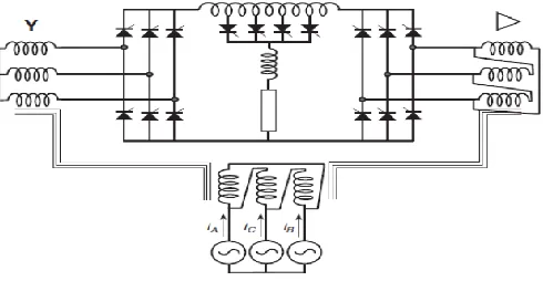
2.3
Three-phase Full-wave Rectifier
Parallel connection via inter phase transformers
permits the implementation of rectifiers for high
current applications. For high voltage series
connection is also possible, as shown in the
full-wave rectifier of Fig.3. With this arrangement, it
can be seen that the three common cathode valves
generate a positive voltage with respect to the
neutral, and a negative voltage is produced by the
three common anode valves.
Fig 3: Three-phase full-wave rectifier
2.4Harmonic Distortion
The currents of the line-commutated rectifiers are
far from being sinusoidal. For example, the currents
generated from the 3 phase full wave rectifier have
the following harmonic content.
Some of the characteristics of the currents, obtained
167
harmonics; the presence of harmonics of order 6k ±
1 for integer values of k; those harmonics of orders
6k+1 are of positive sequence; those of orders 6k −
1 are of negative sequence; the RMS magnitude of
the fundamental frequency is, and the
RMS magnitude of the nth harmonic is
.
3. Formulation of Pulse converters
The 12-pulse rectifier was obtained with a 30◦
phase shift between the two secondary
transformers. The basis for increasing pulse
configurations is provided by the parallel
transformers. For instance, the operation of 24
pulses is achieved by means of four transformers
with 15◦ phase shift, and 48-pulse operation
requires eight transformers with 7.5◦ phase shift.
Fig 4: DC ripple reinjection technique of pulse operation
An ingenious and very simple way to reach high
pulse operation is shown in Figure 4 This
configuration is called dc ripple reinjection. It
consists of two parallel converters connected to the
load through a multistep reactor. The reactor uses a
chain of thyristor-controlled taps, which are
connected to symmetrical points of the reactor. The
thyristors located at the reactor is fired at the right
time; high-pulse operation is reached. The pulse
level operation depends on the number of thyristors
connected to the reactor. The basic level of
operation is multiplied to the two converters.
3.1 HVDC Power Transmission
The use of HVDC systems for interconnections of
asynchronous systems is an interesting application.
Some continental electric power systems consist of
asynchronous networks such as those for the Texas,
Quebec networks in North America, and islands
loads such as that for the Island of Gotland in the
Baltic Sea make good use of the HVDC
interconnections.
Fig 5: Typical HVDC circuit system
4. Simulation Model of Pulse Converters
The present ac–dc converters are cost-effective for
universal line and commercial voltage applications
but are unreliable and fault prone for higher power
applications. Thus, to lighten these problems, multi
stage and multi pulse converters have been
168
custom power switching modes. For high and ultra
high voltage levels the soft switching multi pulse
converters offers attractive merits because the
component count suffices with the cost of the
system.
Fig. 6 Twenty Four pulse controlled converters
with resistive load
Fig. 7 Thirty six pulse controlled converters with
resistive load
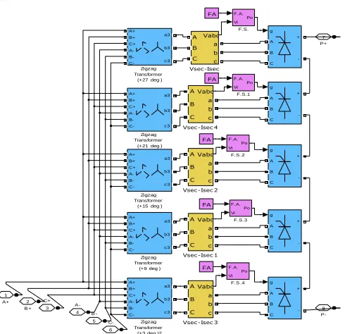
4.1 Twenty Four-Pulse Converter
The below Figure 8 A which is shown below is
having a twenty four pulse thyristorized converter
circuits. Along with two universal bridges in each
group at input side the converter requires 4
star-zigzag transformers, two on each positive phase
group and negative phase group.
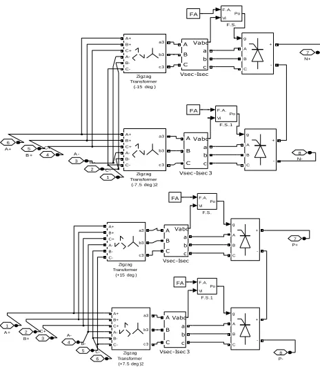
4.4 Thirty Six-Pulse Converter
The simulation model for thirty six pulse
thyristorized converter circuit is shown in Figure 9.
The converter requires 6 star-zigzag transformers at
input side of the converter, 3 in positive phase
group and 3 in negative phase group along with
three universal bridges in each group
Fig. 8 Thirty six pulse controlled converters with
resistive load N-8 N+ 7 A+ 6 B + 5 C+
4 A -3 B
-2 C-1 FA FA Zigzag Transformer (-7.5 deg )2 A+ B+ C+ A- B- C-a3 b3 c 3 Zigzag Transformer
(-15 deg ) A+ B+ C+ A- B- C-a3 b3 c 3 Vsec-Isec 3 Vabc A B C a b c Vsec-Isec Vabc A B C a b c g A B C + -g A B C + -F.S .1 F.A. Vi Po F.S. F.A. Vi Po P-8 P+ 7 C-6 B-5 A-4 C+ 3 B+ 2 A + 1 FA FA Zigzag Transformer (+7.5 deg )2 A+ B+ C+ A- B- C-a3 b3 c 3 Zigzag Transformer
(+15 deg ) A+ B+ C+ A- B- C-a3 b3 c 3 Vsec-Isec 3 Vabc A B C a b c Vsec-Isec Vabc A B C a b c g A B C + -g A B C + -F.S .1 F.A. Vi Po F.S . F.A. Vi Po P -8 P + 7 C-6 B -5 A -4 C+ 3 B + 2 A+ 1 FA FA FA Zigzag Transformer
(+5 deg )2 A+ B+ C+ A- B- C-a3 b3 c 3 Zigzag Transformer
(+25 deg ) A+ B+ C+ A- B- C-a3 b3 c 3 Zigzag Transformer
(+15 deg )1 A+ B+ C+ A- B- C-a3 b3 c 3
Vsec -Isec 3 Vabc A B C a b c Vsec -Isec 1
169
Fig. 9 Thirty six pulse controlled converters with
resistive load
5.
Results and Discussion
Fig.10.Ripple factor, form factor and mean value of
voltage respectively of 24 and 36 pulse generator
P-8 P+ 7 C-6 B -5 A -4 C+ 3 B + 2 A+ 1 FA FA FA FA FA Zigzag Transformer
(+9 deg ) A+ B+ C+ A- B- C-a3 b3 c 3 Zigzag Transformer
(+3 deg )2 A+ B+ C+ A- B- C-a3 b3 c 3 Zigzag Transformer
(+27 deg ) A+ B+ C+ A- B- C-a3 b3 c 3 Zigzag Transformer
(+21 deg ) A+ B+ C+ A- B- C-a3 b3 c 3 Zigzag Transformer
(+15 deg ) A+ B+ C+ A- B- C-a3 b3 c 3 Vsec-Isec 4 Vabc A B C a b c Vsec-Isec 3 Vabc A B C a b c Vsec-Isec 2 Vabc A B C a b c Vsec-Isec 1 Vabc A B C a b c Vsec-Isec Vabc A B C a b c g A B C + -g A B C + -g A B C + -g A B C + -g A B C + -F.S .4 F.A. Vi Po F.S.3 F.A. Vi Po F.S .2 F.A. Vi Po F.S.1 F.A. Vi Po F.S. F.A. Vi Po
0 0.2 0.4 0.6 0.8 1
-50 0 50
Ib: 36 PULSE CONT/36 Source
0 0.2 0.4 0.6 0.8 1
-10 0 10
Ib: 36 PULSE CONT/36 Load
0 0.2 0.4 0.6 0.8 1
-400 -200 0 200 400
170
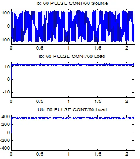
Fig.11.Ripple factor, form factor and mean value of
voltage respectively of 48 and 60 pulse generator
Table 1 Comparative result of the converters
6.
CONCLUSION
An analysis of simulation results was performed
and the following conclusions can be drawn
without loss of generality. Increasing the number of
converter pulses reduces the voltage ripples. Form
factor is also improves though insignificantly. The
harmonics in the supply system are almost
eliminated. The voltage ripples increase as the
firing angle is increased.
References
[1].Wen Jiaopu; Haihong Qin; Shishan Wang; Bo
Zhou, “Basic connections and strategies of
isolated phase-shifting transformers for
multipulse rectifiers: A review”, Asia-Pacific
Symposium on Electromagnetic Compatibility
(APEMC), pp 105-108, 2012.
[2].R Maurya, P Agarwal, S.P Srivastava,
“Performance investigation of Multipulse
Converter for Low Voltage High Current
applications”, IEEE International Conference on
Computer Science and Automation Engineering
(CSAE), pp-211-216, 2011.
[3].P.K Singh, Y.K Chauhan, “Performance analysis
of multi-pulse electronic load controllers for
self-excited induction generator”, International
Conference on Energy Efficient Technologies for
Sustainability (ICEETS), pp-1299-1307, 2013.
[4].A Chaturvedi, D Masand, Gupta, S. Tiwari, S.
Jain, M., “Comparative analysis of three phase
AC-DC controlled multi pulse converter”, IEEE
Students' Conference on Electrical, Electronics
and Computer Science (SCEECS), pp 1-4, 2012.
[5].Valderra, bano, A. Ramirez, J.M. Correa, R.E.,
“A new 84-pulse VSC configuration using
multi-level DC voltage reinjection for especial
171
Industrial Technology (ICIT), pp.1715-1720,
2010.
[6].Xigeng Ma; Chao Li, Lina Bai, Ying Liu,
“Analysis and Mat lab Simulation of 30-Pulse
Rectification System Based on Stretch Triangle
Transformer”, International Conference on
Electrical and Control Engineering (ICECE), pp
3312-3315, 2010.
[7].A N Arvindan, A. Guha, “Novel topologies of
24-pulse rectifier with conventional transformers
for phase shifting”, 1st International Conference
on Electrical Energy Systems (ICEES), pp
108-114, 2011.
[8].I. Sefa, Altin, N. Colak, I. zdemir, S., “18 pulse
controlled rectifier: A case study on UPS”, 13th
European Conference on Power Electronics and
Applications, pp 1-9, 2009.
[9].Singh, B.; Garg, V. Bhuvaneswari, G. , Design
and Development of Autotransformer Based
24-Pulse AC-DC Converter fed Induction Motor
Drive, 7th International Conference on Power
Electronics and Drive Systems, 2007.
[10]. Sahoo, AK. Murugesan, K. Thygarajan, T.,
Modeling and simulation of 48- pulse VSC based
STATCOM using simulinka power system block
set, International Conference on Power
Electronics, 2006. IICPE, India, pp. 303-308,