349 International Journal of Transportation Engineering, Vol.5/ No.4/ Spring 2018
Evaluating the Performance of Dowel in PCC Pavement of
Roads using ABAQUS Finite Element Software
Mahmoud Reza Keymanesh1, Mehrdad Mirshekari Babaki2, Noushin Shahriari3, Ali Pirhadi4
Received: 15. 11. 2016 Accepted: 28. 06. 2017
Abstract
In Portland Cement Concrete (PCC) pavement of the roads, dowels bar transfers vehicle loading to the unloaded slab. Load Transfer Efficiency (LTE) is used to evaluate dowel bars in PCC pavement. This parameter is defined as the vertical displacement ratio of the loaded slab versus the unloaded slab. In this study, the impact of effective factors (friction coefficient between dowel and concrete slab, wheel loading, dowel diameter and dowel spacing) on load transfer efficiency was studied with modeling by using the ABAQUS finite element software. The verification process was presented to increase confidence in model results and the response data from the numerical simulation agrees well with analytical solution. The results show that with increasing the friction coefficient between slab and dowel, load transfer efficiency increases but the failure of concrete around dowel bars was found to initiate at the face of joint. Furthermore, if strains remain in elastic range, increasing in wheel loading magnitude does not lead to reduce load transfer efficiency but dowel diameter or its spacing have an important role on load transfer by dowels.
Keywords: Three-dimensional (3D) modeling, load transfer efficiency, dowel
Corresponding author E-mail: [email protected]
Evaluating the Performance of Dowel in PCC Pavement of Roads using ABAQUS …
International Journal of Transportation Engineering, 350 Vol.5/ No.4/ Spring 2018
1. Introduction
Jointed plain concrete pavement (JPCP) is one of the most widely used types of pavement. This pavement should have joints at regular intervals. A dowel is a tool for transferring load on a slab to another one in joints. Depending on the type of pavement, weather, and implementation experience, it is recommended a maximum joint spacing of 6.1 m for dowelled joints and 4.6 m for non-dowelled joints [Azadravesh , 2010]. The moving of traffic loads over slabs and the temperature changes cause stress in slabs. The main function of dowels is to transfer wheel loads from one slab to another one in such a way that the loading magnitude is equally divided between two slabs. Lack of implement dowel bars, leads to decrease bearing capacity at one end of the slab and if water penetrates into the joint, suction take place between slab and base. It causes creating ripples in joints [Yu et al. 1993]. Using dowels increase PCC pavement life in the long term.
Load transfer is a complicated phenomenon that varies with concrete material, the way of jointing, friction coefficient between dowel and concrete and diameter, spacing and material of dowel. Although circular steel dowels are the most common types of dowels, other shapes and materials may have a better effect on stress distribution. Usually, dowels are placed in the middle of slabs with a 30cm distance between them [Crovetii et al. 2005]. As a general rule, dowel diameter should be about one-eighth the slab thickness. US Federal Highway Administration (FHWA)(1993) suggested dowels with the 3.2cm diameter for highways. The whole length of dowel is usually 45cm that half of which is placed inside each slab [Metin, 2015]. Dowels are placed inside fresh concrete after implementing concrete using special machinery or they are ready for concrete placement as a set of dowels fixed to the base. Although the main role of dowels is to transmit the load between two slabs, they should not inhibit slabs from moving freely because of contractions or expansions [Huang, 1993]. The main damage in the JPCP usually occurs in the joints. Dowel bars connect the slab also transfer the applied loading across the joint
mainly by shear and this is design criteria for dowels. Load transition mechanism in joints by dowels is a complicated mechanism and at such circumstance using finite element (FE) method is appropriate [Jankowiak et al. 2005].
Strain gauge data from full-scale tests collected by the federal aviation administration were analyzed to compute the stress-based Load transfer efficiency (LTE) of joints under moving loads. The effect of static aircraft gear loads and slab size on the LTE of joints was analyzed by using a two dimensional finite-element program JSLAB. Fem-calculated stress-based LTE under static aircraft loading on average was 38% lower than that measured under moving loads. LTE values were similar under various gear positions, gear configurations, and different slab sizes [Wadkar et al. 2011].
Matira employed 3D finite element model the mechanism of load transfer by dowel bar system. Eight node 3D brick element used to model a concrete slab as well as the base support layers. The concrete slab and the base layers were assumed to be linear, elastic and isotropic. Dowel bars were modeled as 3D beam elements having six degrees of freedom per node. The dowel concrete friction value considered was 0.05. [Maitra, 2009].
Misalignment problem practice by improved anchoring of the basket, more reliable is to place the outside dowel 230 mm to 300 from the pavement edge and longitudinal joint and can be shown to result in only a small increase in pavement corner stress [NCHRP 637, 2009]. Loosness in dowel is caused by typical horizontal pavement joint openings and vertical off-set that develop at slab ends. Just a very small vertical off-set or fault along a joint line can result in significant differences in load transfer and deflections of slabs for loading on the side of joint compared to the other [NCHRP 637, 2009].
The maximum vertical displacement ratio of two slabs is one of the parameters for measuring the performance of dowels. The parameter was used in this study for evaluating the efficiency of dowels, illustrate in equation (1):
LTE =𝑈𝑢𝑛𝑙𝑜𝑎𝑑𝑒𝑑
Mahmoud Reza Keymanesh, Mehrdad Mirshekari Babaki, Noushin Shahriari, Ali Pirhadi
351 International Journal of Transportation Engineering, Vol.5/ No.4/ Spring 2018 𝑈𝑢𝑛𝑙𝑜𝑎𝑑𝑒𝑑 = maximum vertical displacement in
unloaded slab
𝑈𝑙𝑜𝑎𝑑𝑒𝑑 = maximum vertical displacement in loaded slab
LTE depends on some factors including dowel diameter and distance, friction coefficient, wheel loading, and concrete pavement thickness.
This paper evaluates the effectiveness factors, including dowel and concrete friction coefficient, the applied wheel loading magnitude on the slab, dowel position in the concrete slab, bar diameter and dowel spacing on load transfer efficiency by dowels with using FE analysis and ABAQUS software.
2. Tabatabaie-Barenberg Model
Tabatabaie and Barenberg (1980) proposed a very simple but realistic model for analysis of dowel-PCC interaction. They used Friebergʼs analysis جFrieberg 1940) of dowels in the rigid pavement based on work presented by Timoshenko (1925). This model deals dowels as beam resting on a spring foundation that illustrated in Figure 1. The spring model compressibility of the PCC slab which means that dowel pressure on the concrete is proportional to the dowel deflection within the concrete. According to the Tabatabaie-Barenberg, the dowel is long enough to be considered infinite in both directions. This assumption does not introduce significant discrepancies if dowel deflections with respect to concrete vanish close to the PCC joint. If the whole action of concrete on the dowel from one PCC slab is P as shown in Figure 1 then deflection of the dowel in the other slab is as following (Timoshenko and Lesser 1925): y = e-βx [P cos βx -β Mo (cos βx - sin βx)] / 2
β3 Ed Id (2)
Where,
y= vertical deformation of PCC under the dowel
x= coordinate along dowel from the face of concrete
Mo= bending moment on dowel at face of concrete
β= the relative stiffness of a dowel bar embedded in concrete
Ed= elastic modulus of dowel bar material, psi Id= moment of inertia of the dowel
The relative stiffness of a dowel bar embedded in concrete, β, is defined as:
β= [ K d / 4 Ed ld]^0.25 (3) Where,
K= modulus of dowel support, psi/in d= dowel diameter, in
Id= π d4 / 64
If the joint wide opening is designated Z, and considering that the concrete slabs are much stiffer than dowels, the moment at the dowel B concrete interface is as follows:
M=-(P_t Z)/2 (4) Substituting Eq (4) into Eq (2) leads to the following expression for the maximum dowel deflection in the concrete:
y=P_t/(〖4β〗^3 EI)(2+βz) (5) The maximum bearing pressure on the concrete is defined by:
σ=ky.=(kP_t)/(〖4β〗^3 EI)(2+βz) (6) One can see that the maximum bearing pressure on concrete depends on the following parameters:
Total load transferred by the dowel Modulus of dowel support
Joint opening Dowel diameter
Dowel modulus of elasticity [James ,2005].
Evaluating the Performance of Dowel in PCC Pavement of Roads using ABAQUS …
International Journal of Transportation Engineering, 352 Vol.5/ No.4/ Spring 2018
3. FE Model Validation with
Analytical Solution
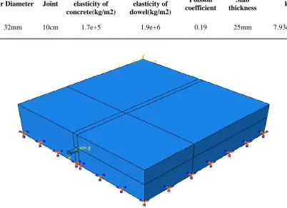
Using ABAQUS software, a simple model was developed to compare Tabatabaei-Barenberg analysis and FE method. In this model, a PCC slab with dimensions of 3.5×3.5m and thickness of 25cm was used and bottom of the slab was constrained at both directions. A bar was placed with a diameter of 32mm and a length of 30cm in the middle of the PCC slab. The Coulomb friction model was applied in this model to create a connection between the bar and PCC slab. The friction coefficient between the dowel and PCC slab (µ) is variable. Because of uniformity between FE model and Tabatabaie-Barenberg model, a vertical point load was applied to the end of the dowel. The load increased from zero to 3.1-tons in linear
amplitude and vertical deflection of dowel at the face of joint (y_0) was recorded. Table 1 shows a summary of modeling input.
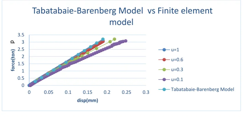
The Figure 3 shows changes in the applied load magnitude on the dowel (p) against bar displacement in the joint (𝑦0) at different
friction coefficients. Due to the limit resources and absence of ability to perform a specialized test procedure, the verification process was done by using Tabatabaie-Barenberg analytical model and the 3D FE was validated with analytical solution for vertical displacement of the dowel. As Figure 3 states, the 3D FE results were relatively close to analytical solution and with decreasing the friction coefficient between the dowel and PCC slab, vertical deflection of the dowel and the difference between analytical model and FE method results increase.
Table 1. Summary of modeling information of both models (analytical and finite element method)
k Slab
thickness Poisson
coefficient Modulus of
elasticity of dowel(kg/m2) Modulus of
elasticity of concrete(kg/m2) Joint
Bar Diameter
7.93e+11 25mm
0.19 1.9e+6
1.7e+5 10cm
32mm
Mahmoud Reza Keymanesh, Mehrdad Mirshekari Babaki, Noushin Shahriari, Ali Pirhadi
353 International Journal of Transportation Engineering, Vol.5/ No.4/ Spring 2018 Figure 3. Validation of 3D FE model with classical solutions
Table 2. The number of elements whose tension damage parameter rate exceed 0.9 The number of elements whose tensional
damage exceed 0.9 The maximum of tension
damages Friction coefficient
39 1.016
1
29 9.90e-1
0.6
21 9.912e-1
0.3
16 9.920e-1
0.1
The concrete damage plasticity method was used to define concrete plastic behavior (Table 4). In this model, degradation of the elastic stiffness is characterized by two damage variables, 𝑑𝑡 and 𝑑𝑐, which are assumed to be
functions of the plastic strains, temperature, and field variables. The damage variables can take values from zero, representing the undamaged material, to one, which represents total loss of strength.
Initially, with increasing the applied load on the dowel, the tensile stress in the elements of concrete arises and then the elements around
the dowel will be damaged. In this section, the impact of friction coefficient on damage ratio (𝑑𝑡) of slab elements has been examined. The
friction between dowel and concrete makes shear stress increases in dowel surface and it will eventuate in applying more tension on the elements of PCC slab which surround the dowel. Given an above-mentioned modeling details and applying the 3.1-tons load on dowel end, some of the concrete elements whose tensile damage ratio (𝑑𝑡) exceeds 0.9 have been
shown in the Table 2 in terms of the friction coefficient.
0 0.5 1 1.5 2 2.5 3 3.5
0 0.05 0.1 0.15 0.2 0.25 0.3
force
(to
n
)
disp(mm)
Tabatabaie-Barenberg Model vs Finite element
model
u=1
u=0.6
u=0.3
u=0.1
Tabatabaie-Barenberg Model
Evaluating the Performance of Dowel in PCC Pavement of Roads using ABAQUS …
International Journal of Transportation Engineering, 354 Vol.5/ No.4/ Spring 2018
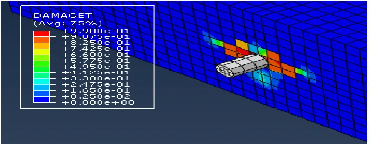
Figure 4. Tension damages parameter of the elements surrounding PCC slab in the friction coefficient of 1
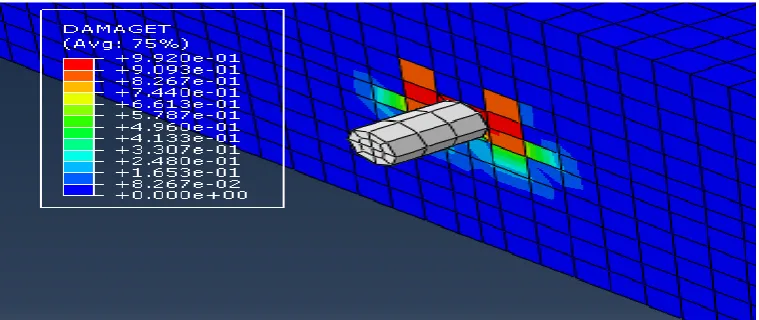
Figure 5. Tension damages parameter of the elements surrounding PCC slab in the friction coefficient of 0.6
Mahmoud Reza Keymanesh, Mehrdad Mirshekari Babaki, Noushin Shahriari, Ali Pirhadi
355 International Journal of Transportation Engineering, Vol.5/ No.4/ Spring 2018 Figure 7. Tension damages parameter of the elements surrounding PCC slab in the friction coefficient of
0.1
According to Figures 4 to 7 and Table 2, increase of friction coefficient from 0.6 to 1 leads to increase in the maximum tensile failure and the number of damaged elements.
The bearing stress in the concrete at the face of the joint is critical for proper function of the dowel bar. If the bearing stress is too much, the concrete will begin to break away where it contacts the dowel bar. According to American Concrete Institute (ACI) committee 325, the allowable bearing stress on the concrete is equivalent to equation (7), therefore the impact of friction coefficient should be considered. 𝒇𝒃 = (𝟒−𝒅
𝟑 )𝒇𝒄 (7)
𝒇𝒃= allowable bearing stress
4. Numerical 3D Modeling for the
Set of PCC Slabs and Dowels
ABAQUS software consist of very powerful modeling programs based on FE analysis which can solve problems from a simple linear analysis to the most complicated non-linear modeling (such as hyperplastic and viscoelastic materials).
4.1 Model Geometry
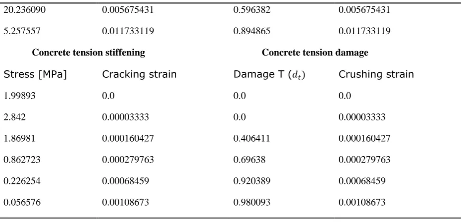
The FE modeling was developed using ABAQUS VER 14.1 software. In this modeling, two PCC slabs with the dimensions of 0.25×3.5×3.5 m were connected by dowels. Dowels bars were 32 mm in diameter and 40 cm in length which were located at the middle of PCC slab with 30cm spacing center to center.
The base was shaped slightly wider than the slab to enable a better distribution of the stresses and widened by 0.5 m for each edge of the slab. The joint width opening was supposed to be 10 mm. In order to study the impact of dowel performance, it was assumed that load transfer only through dowels to adjacent slab [Gauch, 2013].
The standard axle (a single axle with a single wheel on each side) with 8.2-tons load was applied on the center of one PCC slab. The rectangular tire imprint with uniform stress and dimensions of 0.425× 0.315m was simulated. To identify the contact area between the dowel and slab, Coulomb method was used and the friction coefficient between the dowel and PCC slab (µ) was defined. The concrete slab and the base layer were assumed to be frictional contact, and the slab-base friction value is 0.05[Li Luoke et al. 2012].
ABAQUS consist of two main analysis solutions for problems: Standard and Explicit. ABAQUS/Standard can solve a wide range of linear and nonlinear problems involving the static, dynamic and contact response of components. In this paper Standard method with 1 step and static loading was used.
4.2 Material
Evaluating the Performance of Dowel in PCC Pavement of Roads using ABAQUS …
International Journal of Transportation Engineering, 356 Vol.5/ No.4/ Spring 2018
dynamic and cyclic loading. It can model concrete damage in both states of cracking under strain and pumping under pressure.
Constitutive behaviour of concrete is very difficult to capture by using elastic damage models or elastic plastic laws. In elastic damage model irreversible stains cannot be captured. On the other hand when elastic plastic relation is adopted the strain will be overestimated since the unloading curve will follow the elastic slope. In concrete damage model two main failure mechanisms are assumed: tensile
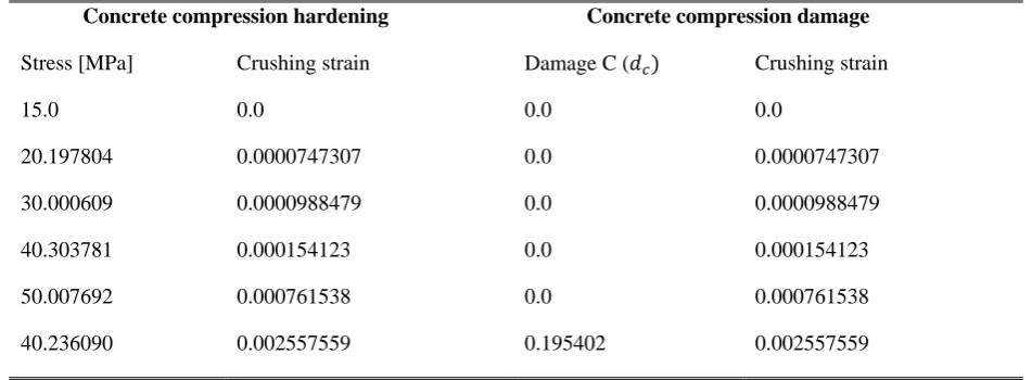
cracking and compressive crushing of the concrete. This model is designed for applications in which concrete is subjected to cyclic loading with alternating tension and compression. In this method, the parameters needed to define concrete plastic model include ψ ،ɛ ،fb/fc and K which respectively are 38, 1, 1.12 and 0.666 degrees. Table 3 was listed the parameters of material definition and concrete damage plasticity constant. The steel dowel bars and base were represented using the elastic isotropic material models.
Table 3. Material properties
value parameter
material
19.7 GPa Modulus of elasticity
concrete
0.19 Poisson coefficient
C3D8R Type of element
7.5 cm The size of smallest element
200 GPa Modulus of elasticity
Steel (dowel) Poisson coefficient 0.3
C3D8R Type of element
5cm The size of smallest element
GPa 7.2 Modulus of elasticity
base
0.35 Poisson coefficient
Table 4. Input parameter for concrete damage plasticity [Azadravesh, 2010] Concrete compression damage Concrete compression hardening
Crushing strain Damage C (𝑑𝑐)
Crushing strain Stress [MPa]
0.0 0.0
0.0 15.0
0.0000747307 0.0
0.0000747307 20.197804
0.0000988479 0.0
0.0000988479 30.000609
0.000154123 0.0
0.000154123 40.303781
0.000761538 0.0
0.000761538 50.007692
0.002557559 0.195402
Mahmoud Reza Keymanesh, Mehrdad Mirshekari Babaki, Noushin Shahriari, Ali Pirhadi
357 International Journal of Transportation Engineering, Vol.5/ No.4/ Spring 2018 0.005675431
0.596382 0.005675431
20.236090
0.011733119 0.894865
0.011733119 5.257557
Concrete tension damage Concrete tension stiffening
Crushing strain
Damage T (𝑑𝑡)
Cracking strain Stress [MPa]
0.0 0.0
0.0 1.99893
0.00003333 0.0
0.00003333 2.842
0.000160427 0.406411
0.000160427 1.86981
0.000279763 0.69638
0.000279763 0.862723
0.00068459 0.920389
0.00068459 0.226254
0.00108673 0.980093
0.00108673 0.056576
Evaluating the Performance of Dowel in PCC Pavement of Roads using ABAQUS …
International Journal of Transportation Engineering, 358 Vol.5/ No.4/ Spring 2018
Figure 9. 3D view of the model by ABAQUS software
5.
The
Impact
of
Friction
Coefficient on Dowel Performance
Friction coefficient between PCC slab and dowel is one of the most effective parameters on the dowel action because, with increasing friction coefficients, bonding increases between PCC slab and dowel and loosness does not occur. The tangential behavior of the dowel was modeled using Coulomb frictional contact between the surfaces. The different friction coefficients were taken as 1 for the perfectly bonded side to 0.1 for the free side of dowel and separation was allowed between the surfaces. The normal behavior of the load transfer was simulated using hard contact pressure definition between the two surfaces. For this purpose,
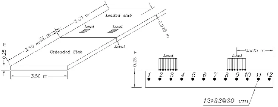
special surface-to-surface elements were used to model hard contact behavior. In this modeling, the friction coefficient between PCC slab and dowel as variables and its impact on the load transfer efficiency of the dowel have been studied. Figure 10 plots the impact of the friction coefficient between the dowel and concrete on the load transfer efficiency of dowels.
Mahmoud Reza Keymanesh, Mehrdad Mirshekari Babaki, Noushin Shahriari, Ali Pirhadi
359 International Journal of Transportation Engineering, Vol.5/ No.4/ Spring 2018 Figure 10. The impact of dowel and concrete friction coefficient on the load transfer by dowels
Figure 11. Impact of friction coefficient on maximum shear stress in PCC slabs and dowel 0.93
0.935 0.94 0.945 0.95 0.955 0.96 0.965
0 0.2 0.4 0.6 0.8 1 1.2
LTE
µ
0.00E+00 2.00E+04 4.00E+04 6.00E+04 8.00E+04 1.00E+05 1.20E+05 1.40E+05
0 0.2 0.4 0.6 0.8 1 1.2
Ƭ
)
con
tact
shear
(
(Pa)
µ
Loaded slab
Unloaded slab
Evaluating the Performance of Dowel in PCC Pavement of Roads using ABAQUS …
International Journal of Transportation Engineering, 360 Vol.5/ No.4/ Spring 2018
According to the Figure 11, shear stress in adjacent slabs is slightly different in the elements of PCC slab which surround the dowels (contact shear), and shear stress is higher in the unloaded slab. This difference increases as friction coefficient increases and Shear stress is almost equal in the dowel and unloaded PCC slab.
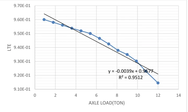
6. The Impact of Wheel Load on
PCC Slab on Dowel Load Transfer
Under vehicular loading the structural response of concrete pavement was affected by magnitude of applied wheel loading. In this section, the applied load on a slab (weight of axle) increases from zero to 12 tons in linear amplitude and its impact on the LTE was illustrated in Figure 12.
According to the figure, although the applied load on slab increases, the coefficient of the performance does not change significantly. It is because all the strain of materials and surfaces are in the elastic range.
7. The Impact of Diameter and
Dowel Spacing on the Performance
of Dowel
In Tabatabaie-Barenberg equation, dowel vertical displacement has a negative relationship with dowel diameter. Consequently, as bar diameter increases, load transfer efficiency of dowels increases as well. In this section, the impact of dowel diameter and spacing has been examined. The diameters of bars were taken 22mm, 25mm, 28mm, 32mm and 36 mm. Figure 13 states the impact of bar diameter on the performance of dowels.
Figure 12. Impact of the axle weight increases on the load transfer coefficient of the dowel y = -0.0039x + 0.9677
R² = 0.9512
9.10E-01 9.20E-01 9.30E-01 9.40E-01 9.50E-01 9.60E-01 9.70E-01
0 2 4 6 8 10 12 14
LTE
Mahmoud Reza Keymanesh, Mehrdad Mirshekari Babaki, Noushin Shahriari, Ali Pirhadi
361 International Journal of Transportation Engineering, Vol.5/ No.4/ Spring 2018 Figure 13. Impact of dowel diameter on the performance of dowel
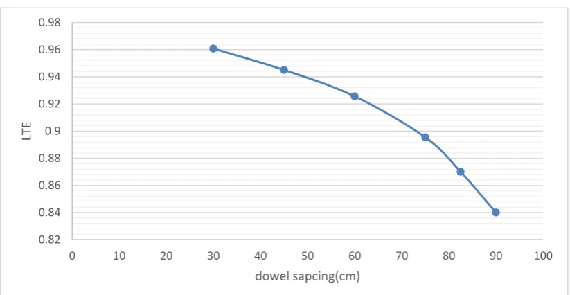
Figure 14. Relation between the dowel spacing and load transfer efficiency
Dowel bars transfer the loads across pavement joint primarily by shear action. When one panel of the pavement is loaded, the panel is deflected along with the dowels connecting the loaded panel with an adjacent panel and in this process the dowels transfer part of the load to the unloaded panel. In designing dowel bars by analytical method, it is supposed that the ratio of vertical displacement of two PCC slabs is equal; consequently, load transfer efficiency (LTE) equals 1, and each dowel bears shear force with an inverse ratio of the distance from
load point. Therefore, the amount of shear in the dowel changes linearly, and the maximum shear occurs in the first dowel next to the wheel load. The shear of each dowel has a reverse relationship with the distance of dowel to wheel load place. The higher the number of dowels (less distance between dowels) leads to lower the amount of shear force on each dowel. Figure 14 illustrates the impact of distance between dowels on LTE. Figure 15 illustrates the impact of dowel bar numbers (distance between them) on the maximum shear force on dowels. The
0.88 0.89 0.9 0.91 0.92 0.93 0.94 0.95 0.96 0.97 0.98
36 32 28 25 22
LTE
dowel diameter(mm)
LTE
LTE
0.82 0.84 0.86 0.88 0.9 0.92 0.94 0.96 0.98
0 10 20 30 40 50 60 70 80 90 100
LTE
Evaluating the Performance of Dowel in PCC Pavement of Roads using ABAQUS …
International Journal of Transportation Engineering, 362 Vol.5/ No.4/ Spring 2018
maximum shear in all plans happened beneath one of loading axle wheels (8.2 tons).
Figure 15. Relation between dowel spacing and maximum shear in dowel
Table 5. Distance and diameter of bars in dowel performance coefficient
Dowel spacing (mm)(dowel diameter=32mm) dowel diameter (mm)(dowel spacing=300mm)
900 750
600 450
300 22
25 28
32 36
0.00122 0.00132
0.00154 0.00203
0.00292 0.00138
0.00178 0.00224
0.00292 0.0037
As/m(𝑚𝑚2)
As the Figure 15 shows, as the distance between dowels increases (their numbers decreases), the maximum shear force increases. And the shear force has a reverse relation with the distance between dowels. For example, if the distance between dowel bars is tripled, shear force triple in them and the diagram above has almost a linear relation. Consequently, as the distance between dowels increase, LTE decreases and the maximum shear force increases in the dowel.
In this section, considering the impact of bar diameter and bar spacing on dowel function, a new term as (As/m) in Table 5 and Figure 16 represents dowel section area per dowel spacing of PCC slab.
According to the Figure 16, there is a proper relationship between the impact of dowel area and spacing on LTE. In fact, increasing dowel area has similar effect on the performance of dowels, unlike dowel spacing reduction.
3.27E+03
4513
5.76E+03
7265 8.25E+03
9.35E+03
y = 99.3x + 70.481 R² = 0.9885
0.00E+00 1.00E+03 2.00E+03 3.00E+03 4.00E+03 5.00E+03 6.00E+03 7.00E+03 8.00E+03 9.00E+03 1.00E+04
0 10 20 30 40 50 60 70 80 90 100
Max
shear
force
in dowel(N)
Mahmoud Reza Keymanesh, Mehrdad Mirshekari Babaki, Noushin Shahriari, Ali Pirhadi
363 International Journal of Transportation Engineering, Vol.5/ No.4/ Spring 2018 Figure 16. Impact of dowel section area and dowel spacing on LTE
Figure 17. Dowel placement point
8. The Impact of Dowel Placement
on Dowel Performance
In jointed PCC pavements, the dowel is usually located in the center of PCC slab, but sometimes it is not placed in ½ of the height of PCC slab due to some operational problems (such as thermal reinforcement). As Figure 17 shows, dowels were placed within PCC slab and performance of dowels was studied at different height.
According to the Figure 17, the most appropriate height for placement of dowels is ½ of the height of PCC slab.
9. Conclusion
The following conclusions were developed based on the analysis of 3D FE model that representing valuable insight on the behavior of the slab-dowel system when subjected to wheel loading. The numerical results were validated with classical analytical solution of dowel
0.84 0.86 0.88 0.9 0.92 0.94 0.96 0.98
0.00000 0.00100 0.00200 0.00300 0.00400
LTE
As/m
dowel diametere
dowel spacing
0.954
0.961
0.952
0.946 0.948 0.95 0.952 0.954 0.956 0.958 0.96 0.962
Evaluating the Performance of Dowel in PCC Pavement of Roads using ABAQUS …
International Journal of Transportation Engineering, 364 Vol.5/ No.4/ Spring 2018
displacement at the face of joint. Conclusions from the numerical investigations are summarized below:
Results obtained from the model shows that LTE was intensive to friction coefficient where it significantly increased as friction changed. On the other hand, deflection base LTE increase with friction coefficient increase. Furthermore, the friction between concrete and dowel can cause the development of the initial damage in the concrete elements near dowel bars.
It was observed that with friction coefficient range increase from 1to 0.1, the LTE reduce by around 3% and maximum contact shear stress between concrete and dowel bars in loaded and unloaded slab decrease by around 225% , 600% respectively.
For rang of applied load magnitude, when strain of concrete element is in the elastic range, the LTE coefficient does not change significantly.
Results demonstrate that LTE for 300 mm dowel spacing was computed to be about 1.5%, 3.6%, 6.8 and 15% larger than for 450 mm, 600 mm, 750 mm and 900 mm spacing cases respectively.
It can be observed that amount of the load transfer increases as the dowel diameter increases and LTE varies from almost 0.965 for 32 mm dowel diameter case to approximately 0.91 for 22 mm dowel diameter.
In addition to that, the maximum amount of LTE occurs when dowel bars are placed in half the height of the slab.
10. References
-ARA and ERES Consultants Division (2004) " Guide for the mechanistic-empirical design of new and rehabilitated pavement structures (NCHRP 1-37A)", Final Report Prepared for National Cooperative Highway Research Program (NCHRP), Transportation Research Board,
National Research Council, Washington D.C, USA.
-Azadravesh, Ehsan (2010) "Generating a 3D model for evaluating the joint opening effects on load transfer efficiency in concrete pavements, using ABAQUS ", 5th. National Congress on Civil Engineering, Ferdowsi University of Mashhad, Mashhad, Iran.
-Crovetti, James and Khazanovich, Lev (2005) "Early opening of Portland Cement Concrete (PCC) pavements to traffic", Technical Report, Marquette University, Department of Civil, Construction and Environmental Engineering, Minnesota, USA.
-Demir, Serhat and Husem, Metin (2015) " Investigation of bond-slip modelling methods used in FE analysis of RC members", Structural Engineering and Mechanics, An Int'l Journal Vol. 56, No. 2, pp. 11-28
-Friedberg, B. F. (1940) "Design of dowels in transvers joints of concrete pavements", Transactions of the ASCE, Vol. 122, No. 2, pp. 146-154.
-Ghauch, Ziad (2013) "Finite element investigation of the deterioration of doweled rigid pavements", Department of Civil Engineering Lebanese American University
-Han, Jin and Seong-Min, Kim and Wonseok, Chung and Yong Hyeon, Lee (2014) "Effect of joint type on rigid airfield pavement behavior ", KSCE Journal of Civil Engineering, Vol. 18, No. 5, pp. 1389-1396.
-Huang, Yang (1993) "Pavement analysis and design", USA: Prentice Hall, New Jersey.
Mahmoud Reza Keymanesh, Mehrdad Mirshekari Babaki, Noushin Shahriari, Ali Pirhadi
365 International Journal of Transportation Engineering, Vol.5/ No.4/ Spring 2018 constitutive model", Foundation of Civil
and Environmental Engineering, Vol. 1, No. 6, pp. 54-69.
-Karlsson, Hibbitt and Sorensen, Inc. (2015) “ABAQUS, Finite Element Computer Program, Version 14.1.0”, Karlsson Hibbitt and Sornsen Inc.
Luoke, L., Tan, Y., Xiangbing, G. and Yunliang, L. (2012) "Characterization of contact stresses between dowels and surrounding concrete in jointed concrete pavement", International Journal of Civil and Environmental Engineering, Vol.12, No. 05, pp. 16-24
-Mackiewicz, Pioter (2015) "Analysis of stresses in concrete pavement under a dowel according to its diameter and load transfer efficiency", Canadian Journal of Civil Engineering, Vol. 42, No. 11, pp. 845-853.
-Maitra, Swati Roy Reddy, K. S. and Ramachandra, L. S. (2015) "Estimation of joint and interface parameters for the finite element analysis of jointed concrete pavement using structural evaluation results", International Journal on Pavement Engineering and Asphalt Technology, Vol.16, No. 2, pp. 21-38.
-National Cooperative Highway Research Program (2009) "NCHRP Guidelines for dowel alignment in concrete pavement", Rep. No. 637, Transportation Research Board, National Research Council, Washington, D.C, USA.
-Sharif Tehrani, Saleh and Hosseini Lavasani, Seyed Hossein (2016) "The of concrete pavement mix design parameters on durability under freeze and thaw
condition", International Journal of Transportation Engineering, Vol. 4, No.3, pp. 211-224.
-Sii, H. B., Chai, G. W., Staden, R. V. and Guan, H. (2014) "Development of prediction model for doweled joint concrete pavement using three-dimensional finite element analysis", Applied Mechanics and Materials, Vols. 587-589, pp. 1047–1057.
-Tabatabaie, A. M. and Barenberg, E. H. (1980) "Structural analysis of concrete pavement systems", Journal of Transportation Engineering, ASCE, Vol. 106, No. 5, pp. 493-506.
-Timoshenko, S. and Lessels, J. M. (1925) "Applied elasticity", Westinghouse Technical Night School Press, Pittsburgh, Pennsylvania, USA
-Wadkar, A., Mehta Y., Guo, E. and Kettleson, W. (2011) "Load-transfer efficiencies of rigid airfield pavement joints based on stresses and deflections", Journal of Materials in Civil Engineering, Vol. 23, No. 8, pp. 1171–1180.
-Yu, H. T., Smith, K. D., Darter, M.I., Jiang, J. and Khazanovich, L. (1993) "The performance of concrete pavements", Volume III, Report No. FHWA- RD-95-111. Federal Highway Administration, Washington, DC, USA.