Please cite this article as: S. Akbarnezhad, A. Soltani Goharrizi, M. Salmanzadeh, Eulerian- Lagrangian Simulation of Particle Capture and Dendrite Formation on Binary Fibers, International Journal of Engineering (IJE), IJE TRANSACTIONS A: Basics Vol.31, No. 7, (July 2018) 1004-1011
International Journal of Engineering
J o u r n a l H o m e p a g e : w w w . i j e . i rEulerian Lagrangian Simulation of Particle Capture and Dendrite Formation on
Binary Fibers
S. Akbarnezhad*a, A. Soltani Goharrizia M. Salmanzadehb
a Department of Chemical Engineering, Shahid Bahonar University of Kerman, Kerman, Iran b Department of Mechanical Engineering, Shahid Bahonar University of Kerman, Kerman, Iran
P A P E R I N F O
Paper history:
Received 10 November 2017
Received in revised form 23 December 2017 Accepted 04 Januray 2018
Keywords: BinaryFibers Eulerian-Lagrangian Dendrite Formation Deposition Mechanisms
A B S T R A C T
The capture efficiency of the small aerosol particle is strongly influenced by the structure of fibrous layers. This study presents particle deposition and dendrite formation on different arrangements of binary fibers. 2-D numerical simulation is performed using the open source software of OpenFOAM. In the instantaneous filtration of a single fiber, obtained results are in good agreement with the existing model. Results showed that addition of nanofiber to microfiber led to high capture efficiency for the particle size 50nm at the cross arrangement with fibers distance 2µm. When particle gets larger, i.e. 150 nm, binary fibers have higher capture efficiency and pressure drop than the single microfiber at all arrangements, especially for the fibers distance 1.5 µm. Therefore, the good fibers arrangement here seems the cross arrangement with the high capture efficiency, average pressure drop and fibers distance 2 µm.
doi: 10.5829/ije.2018.31.07a.01
NOMENCLATURE
𝐶𝐷 Drag coefficient Re𝑝 Reynolds number of particle
𝑑𝑓𝑚 Diameter of microfiber 𝑆𝑡 =𝜌𝑝𝑑𝑝 2𝐶
𝑐𝑉
18𝜇𝑑𝑓
⁄ Stokes number
𝑑𝑓𝑛 Diameter of nanofiber 𝑇 Temperature
𝑑𝑃 Particle diameter 𝑈 Fluid velocity
𝐸 Efficiency of loaded filter 𝑈𝑝 Particle velocity
𝐸0 Efficiency of clean filter Greek Symbols
𝐹𝐵 Brownian force 𝛼 Solid volume fraction or SVF
𝐹𝐷 Drag force 𝛾 Kinematic viscosity
𝑘𝐵 Boltzmann constant 𝜆 Mean free path 𝑘𝑝𝑝 Permeability constant (m2) 𝜇 Dynamicviscosity
𝑙 Fiber length ρ Density of fluid
𝑀 Mass of loaded particle per fiber volume 𝜌𝑝 Density of particle
𝑚𝑝 Mass of particle 𝜑 Occupied volume fraction of cell by particle
𝑃 Pressure
1. INTRODUCTION1
The motion and deposition of particle phenomena can be seen in many fields such as, environment, energy and chemical industry [1]. Separation of the small particle is
*Corresponding Author’s Email: [email protected] (S. Akbarnezhad)
an important challenge for researcher due to great concern for human health and the environment risks [2-4]. Filtration is an effective technique for removing small particles from the fluid because of being easy to use, inexpensive and high collection efficiency.
filter is widely applied due to its convenient, simple and general features [5]. Current researches in field of fabric filters focused on the filtering mechanisms, efficiency and pressure drop [5]. The base of the classic filtration theories is formed with Single fiber efficiency (SFE), which defines the efficiency of a single fiber that is placed in a cell [6]. Three mainly mechanisms are considered for the particle capture by filtration; impaction, interception and Brownian diffusion [7]. The efficiency of a fiber obtain the sum of the efficiencies from each individual mechanisms [8]. A variety of semi-empirical expression are developed for predicting the efficiency and pressure drop of filters. These expressions are made for clean filters in initial time of filtration [6, 9-11]. However, since the filtration process keeps on for a long time, the filter doesn’t remain clean during the particle loading time. Particles deposit on the fibers and form the dendrite structures with complicated geometries. These structure have eligible effect on the efficiency and pressure drop of the filter. A preliminary model for dendrite formation was developed at particle capture mechanism of interception by Payatakes and Tien [12]. Later, this model improved and extended for impaction and Brownian diffusion mechanisms [13, 14], where the effect of dendrite formation on the flow field was not assumed. Kanaoka et al. [15] simulated the dendrite structure on a single fiber by the Monte-Carlo technique in a Kuwabara cell. They presented a linear formula for SFE of a loaded fiber to clean fiber as mass loaded on the fiber at interception regime. However, no recalculating of flow field was considered during of dendrite growth. Filippova and Hanel [16] and Lantermann and Hanel [17] also considered the flow field recalculation in their studies. Also, Hosseini and Tafreshi [18] simulated the 3-D dendrite formation on a single fiber using the ANSYS-Fluent CFD code. They presented a methodology, which is used during instantaneous particle loading, to explain the effect of the different capture mechanisms on the filter performance. Furthermore, the necessary condition for recalculation of the flow filed was that the total volume of deposited particles to be close to 5 % of the fiber volume [18]. Rafał Przekop and Leon Gradoń [19] modeled the deep bed filtration considering the effect of particle growth on the filter structure and flow field. Their model was able to predict the dynamic filter behavior during instantaneous particle loading.
Moreover to the particle capture mechanisms, other parameters such as, filter structure, solid volume fraction (SVF), filter thickness, the microstructure of disordered fibers in fibrous materials, filtration velocities and fiber diameters can also be effective on the filter performance and the particle capture process [20-22]. Wang et al. [23] simulated the effect of different fiber arrangements on the capture efficiency and pressure drop of multi-layer fiber filters where
The experimental results of Podgorski et al. [25] showed that the capture efficiency of the small aerosol particle is strongly influenced by the structure of nanofibrous layers. Since the nature of fibrous filters causes a difficulty to investigate the details of particle deposition and dendrite formation, it offers to follow numerical simulation of the filtration process than experiments.
The present study investigates the influence of the binary system of the nano- and microfiber on small aerosol particles captured and dendrite formation (particle size 50 nm and 150 nm). The simulation is performed using open source software of OpenFOAM. Here, it is utilized a methodology for particle deposition and growth during instantaneous particle loading. The icoLagrangianFoam solver of OpenFOAM 2.2.0 is extended for simulation of the particle capture and dendrite formation on binary fibers surface. The effects of fibers arrangement and distance between fibers on the capture efficiency, pressure drop and dendrite formation of particles are investigated.
2. NUMERICAL SIMULATION
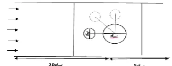
2. 1. Problem Description Figure 1 shows an
example of the 2-D computational box, which consists of two fibers with different diameter 500 nm and 2 µm. A square medium is considered around of fibers as a solid volume fraction of filter medium [18]. For having developed flow the entrance of filtration medium, inlet length of channel is considered bigger than outlet length. Aerosol particles with diameter of 50 and 150 nm are injected randomly through inlet patch to the system. The air flow of system assumes to be laminar and incompressible with constant density, 𝜌 and viscosity,𝜇.
2. 2. Equation of Motion In this study, Eulerian and Lagrangian approaches are used to compute the fluid flow and particle phase equations, respectively. Since the volume fraction of particles in the continuous phase is less 12 %, the particle-particle interaction and particle influence on continues phase is ignored [26]. Particles are randomly injected with positions along the inlet boundary, which is set so as to control the inlet particle concentration (particle number 4000/s). The one way coupling approach is applied for 2-D continuity and momentum equations are solved for gas phase stated as follows [27]:
𝜕𝑈
𝜕𝑥+
𝜕𝑉
𝜕𝑦= 0 (1)
𝜌 (𝑈𝜕𝑈
𝜕𝑥+ 𝑉
𝜕𝑈 𝜕𝑦) = −
𝜕𝑃 𝜕𝑥+ 𝜇 (
𝜕2𝑈
𝜕𝑥2+
𝜕2𝑈
𝜕𝑦2) +
𝜇𝜑
𝑘𝑝𝑝𝑈 (2)
𝜌 (𝑈𝜕𝑉𝜕𝑥+ 𝑉𝜕𝑉𝜕𝑦) = −𝜕𝑃𝜕𝑦+ 𝜇 (𝜕𝜕𝑥2𝑉2+
𝜕2𝑉
𝜕𝑦2) + 𝜌𝑔𝑦+
𝜇𝜑
𝑘𝑝𝑝𝑉 (3)
In the simulation strategy used in this study, the inlet velocity is considered to be 0.001 m/s. Furthermore, it is assumed that the continuum flow is dominant with microfiber diameter 2 µm. Moreover, symmetry boundary conditions are used for the sides of the channel. The reason for this boundary condition is to prevent net flows in lateral sides [28]. Also the air flow enters the computational domain through inlet velocity and leaves through boundary condition of the outlet pressure, respectively. The no-slip boundary condition is used on the wall of fibers.
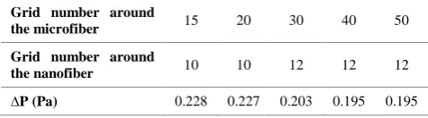
The computations are performed using the extended solver of icoLagrangianFoam with an unstructured mesh around the fibers to solve for two-dimensional flow. The grid number around the nano- and microfiber was 12 and 40 after grid independence test, respectively. This test is done on the pressure drop of the net air flow in binary fibers with the horizontal arrangement (Table 1). There are many different numerical schemes in the OpenFOAM which can be applied to discrete the continuity, momentum and particle equations. In this study, the finite volume method based on the PISO algorithm for pressure-velocity coupling is used. The numerical discrete schemes are chosen as follows: the convection terms with the Gauss cubic scheme, the Laplacian term with the Gauss linear corrected scheme, the gradient of pressure term with the Gauss vanleer
TABLE 1. Grid independence test on the pressure drop of binary fibers
Grid number around
the microfiber 15 20 30 40 50
Grid number around
the nanofiber 10 10 12 12 12
∆P (Pa) 0.228 0.227 0.203 0.195 0.195
scheme and also the derivative of time with the Euler implicit scheme.
2. 3. Particle Transport Equation In Lagrangian
approach, each particle tracks throughout the solution domain. The particle's position in time obtains by
integrating the force balance on a given particle. In this study, the acting forces on particle are drag and Brownian forces. Since particle sizes are considered to be small with diameters 50 and 150 nm, impaction mechanism practicallydoes not exist. Li and Ahmadi [29] concluded the air drag force as a dominant force on the particle when 𝑅𝑒𝑝= 𝜌𝑈𝑑𝑝⁄𝜇 < 1. Therefore, the equation of particle motion stated as follows:
𝑚𝑝𝑑𝑈𝑑𝑡𝑝= 𝐹𝐷+ 𝐹𝐵 (4)
In this study Particles are assumed to have a spherical shape. Therefore, in OpenFOAM the air drag force for spherical particle is defined as follows [30]:
𝐹𝐷=3𝑚4𝜌𝑝𝜇𝐶𝐷𝑅𝑒𝑝
𝑝𝑑𝑝2 (𝑈 − 𝑈𝑝) (5)
In Equation (5) the expression for drag coefficient 𝐶𝐷, is presented in the following form [30]:
𝐶𝐷= 24
𝑅𝑒𝑝 𝑅𝑒𝑝≤ 0.1
(6)
𝐶𝐷= 24
𝑅𝑒𝑝(1 +
1 6𝑅𝑒𝑝
2
3) 0.1 ≤ 𝑅𝑒𝑝≤ 1000
𝐶𝐷= 0.424 𝑅𝑒𝑝> 1000
where
𝑅𝑒𝑝=
𝜌𝑓𝑑𝑝|𝑈−𝑈𝑝|
𝜇𝑓 (7)
Furthermore, Brownian force acting on the particle is described in literature [31]:
𝐹𝑏= 𝐺√
𝜋𝑆𝑜
∆𝑡 (8)
where G is a vector whose components are independent zero-mean, unit variance Gaussian random numbers [32]. The components of the Brownian force for particles are white noise processes, with spectral intensities described by Equation (8) [32]:
𝑆𝑛𝑖,𝑗= 𝑆𝑜𝛿𝑖,𝑗 (9)
𝑆𝑜= 216𝛾𝑘𝐵𝑇
𝜋2𝜌𝑑 𝑝5(𝜌𝑝𝜌)
2
𝐶𝑐
(10)
The value of Cunningham correction factor, Cc and the
mean free path, λ are determined using Equations (11) and (12) stated as follows:
𝐶𝐶= 1 +2𝜆
𝑑𝑝(1.257 + 0.4𝑒𝑥𝑝 (−0.55 (
𝑑𝑝
𝜆 = 0.385(𝜌𝑝𝑑𝑝𝑘𝐵𝑇
𝜇2𝜋2 )1/2 (12)
2. 4. Particle Tracking Algorithm in OpenFOAM The icolagrangianFoam solver of OpenFOAM is a power algorithm for particle tracking. This algorithm is presented in detail by Macpherson et al. [33] and also in brief by Mead-Hunter et al. [31]. The extended solver for simulating dendrite formation of particle on fiber surface is as follows. First, the algorithm finds all cell of the fiber wall (a boundary face for particle deposition). Then, it starts marking coordinates of occupied cells on the fiber wall from particle. The particle deposit on wall face when the particle distance from wall face or last deposited particle is smaller than particle radius. So deposited particle in the algorithm have no more movement and removes from the particle tracking domain. Then, adding a source term to momentum equation (Equations (2) and (3)) can prevent to flow through these marked cells. Like this source term, Saleh et al. [34] considered a sink term to add momentum equation that causes an artificial pressure drop for the flow when passing through these occupied cells.
3. RESULTS AND DISCUSSION
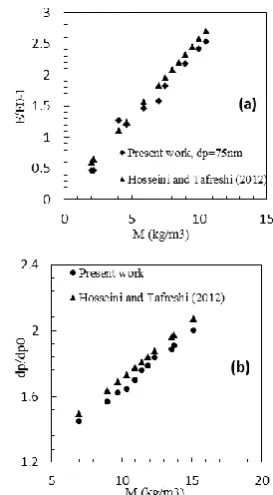
It is necessary to assess the accuracy of the results obtained from the modified Lagrangian approach used in this numerical work. In this section, validation of the particle deposition efficiency (the number of deposited particles to the total number of particles injected into the domain of simulation) and pressure drop is performed by comparing the results with those achieved by Hosseini and Tafreshi [18]. Figure 2 shows the normalized single fiber efficiency (the ratio of the average single fiber efficiency E to the efficiency of clean fiber E0) and pressure drop versus mass of the
deposited particles on a fiber. Two recent validations show good agreement with the obtained results from this simulation.
3. 1. Deposition Pattern and Dendrite Formation of Different Fibers Arrangement and Distance The shape of fibers will change during particle loading depending on particle deposition mechanisms. As the Brownian diffusion is dominant, particle trend to form a uniform distribution of the particle deposition and dendrite chain around the fiber. Interception mechanism mainly causes the growth of dendrites on the lateral sides of fiber. Particles deposit in front of fiber when the impaction mechanisms is dominant. In this study, two distances of 1.5 and 2µm between centers of binary fibers were considered for observing how the particle capture on fiber surfaces.
Figure 2. (a) Normalized single fiber efficiency vs. fiber loading M for a fiber with df=1 µm and 𝛼 = 5%, (b)
Normalized pressure drop for a fiber with df=20µm and
dp=2µm.
Figure 3 shows the particle deposition for the particle size 50 nm on a single fiber and binary fibers in different arrangement and distance. Particles deposit and grow around the binary fibers for three arrangements like the single fiber. In the horizontal arrangement, the nanofiber competes with microfiber to capture particles (top-right). In the other hand, this arrangement is similar to single fiber for the particle deposition and dendrite formation. But the faster dendrite formation on the nanofiber causes these dendrite chains to act as a good collector for the next particle deposition than later microfiber. So, there is a very small dendrite chain around the microfiber, which means that it needs more loading time for having longer dendrite.
At the vertical arrangement, binary fibers have the same uniform deposition around the fibers (bottom-right). In cross arrangement, binary fibers collect the particle on surfers with a dendrite chains around of fibers. The reason of the more growth of dendrite chains on the nanofiber can be similar to horizontal arrangement (bottom-left). These deposition patterns here have been observed in the other numerical simulation results, which have been done by lattice-Boltzmann method [21, 35]. There is a fairy good agreement in shape of dendrites with reference results. Also, the smaller distance of fibers cause more uniformly growth of particle on fiber surfaces at all fiber arrangements.
Figure 4 presents the effects of the fibers arrangement and distance on the particle deposition upon the interception mechanism. In this subsection, the particle size was considered to be 150nm. Generally, interception mechanism can be dominant for particles in range of 0.1-1µm [35]. It can be seen in Figure 4 that deposition of the particles created dendrite chains close to sides of the single fiber (top-left). This deposition pattern is in qualitative agreement with the observation of Hosseini and Tafreshi [18]. When there is a horizontal arrangement, nanofiber has a shielding effect for the back microfiber and the particle deposit with dendrite chains on its lateral sides clearly (top-right). But for two others cross and vertical arrangements, nano- and microfiber of binary system contribute to capture and form dendrite on surfaces. Also the location of the dendrite chains moves from 45o of microfiber
surface to middle of it (bottom-left and right). In fact the faster dendrite formation on nanofiber surface increases the local fluid velocity at the gap domain between fibers. Therefore, here, the Peclet number of particles increases, which means that particles move to stream lines of close to microfiber surface and deposited on surface layer [23].
3. 2. The Effect of Different Fibers Arrangement and Distance on Capture Efficiency During
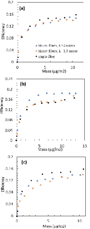
Particle Loading Figures 5 and 6 show the capture
efficiency of the single fiber and different arrangement and distance of binary fibers as mass loaded for the particle size 50 and 150 nm, respectively. Results indicate that the capture efficiency increase fairly constant with increasing the loaded mass on fiber surfaces at all different arrangements (Figures 5a-c and 6a-c). In this subsection, the fiber distance of 1.5 and 2µm between centers of binary fibers are considered for evaluating the performance of binary fibers arrangement in the particle capturing process. It was concluded that the fibers arrangement and distance have a clear effect on the particle capture efficiency and the pressure drop. In fact, a good arrangement causes a high efficiency and a lower pressure drop. In horizontal arrangement of binary fibers and the particle size 50 nm, capture
efficiency have a fairly same increasing as mass loaded for two fibers distances. For the cross arrangement, increasing of capture efficiency is higher for fibers distance 2 µm. When fibers distance decreases to 1.5 µm, the capture efficiency follows a similar trend of the single microfiber efficiency.
Figure 4. Deposition pattern and dendrite formation of particle size 150 nm in different fibers arrangement and distance in contrast with a single microfiber.
Figure 6 Capture efficiency of different arrangements of binary fibers with fibers distance 1.5 and 2µm as mass loaded for the particle size 150 nm (a) the horizontal arrangement, (b) the cross arrangement, (c) the vertical arrangement
The capture efficiency of single microfiber is higher than binary fibers with different fibers distance in the vertical arrangement.
For the particle size 150 nm (Figure 6), binary fibers have higher efficiency at the cross and horizontal arrangements than the single microfiber, especially for smaller fibers distance L=1.5 µm. In the other hand, in vertical arrangement with fibers distance 1.5 µm, the capture efficiency of binary fibers is equal with the single fiber, but fibers distance 2 µm causes the higher efficiency for binary fibers.
3. 3. Pressure Drop of Different Fibers Arrangement and Fibers Distance During Particle
Loading Figures 7 and 8 show the generated
pressure drop by different fibers arrangement and fibers distance during particle loading in contrast to the single microfiber, respectively. In Figure 7, the pressure drop is differentially increasing during particle loading. But the value of the pressure drop is different in each fibers arrangement. In the horizontal arrangement of fibers, the
pressure drop is lower, while for the vertical arrangement, it shows a higher value. Generally, in Brownian diffusion, uniform deposition of particles slowly changes the cross section of fiber. Therefore, the rate of increasing of the pressure drop is less than interception mechanism. Also adding a nanofiber to microfiber generates a more resistance for fluid flow than single microfiber at all fiber arrangements.
As shown in Figure 8, the pressure drop increases with the different rate for the single microfiber and fibers arrangement. It can also be seen that the increasing of the pressure drop of binary fibers is similar to the single fiber after 140µg/m2 for fibers
distance 2 µm at the horizontal arrangement. But for the fiber distance 1.5 µm, the pressure drop increases higher. However, in the cross and vertical arrangement, the pressure drop of binary fibers is higher than single microfiber with fibers distance 1.5 and 2µm. Because, as it is mentioned before, the deposition of particle upon interception increases the cross section of fibers, which causes higher pressure drop.
Figure 8. Pressure drop of different arrangements of binary fibers with fibers distance 1.5 and 2µm as mass loaded for the particle size 150 nm (a) the horizontal arrangement, (b) the cross arrangement, (c) the vertical arrangement
In vertical arrangement, two fibers simultaneously collect particles and form dendrite formation sides of fibers which shows that in this case pressure drop increases higher than other arrangements.
4. CONCLUSION
This study utilized and extended the
icoLagrangianFoam solver of open FOAM for the particle capture and growth simulation to investigate the pressure drop and capture efficiency of binary fibers. It was found that the adding of nanofiber to microfiber causes the higher capture efficiency for particle size 50nm at the cross arrangement of binary fibers, while the pressure drop is fairly low and close together for two fiber distances at the cross arrangement. It was demonstrated that the smaller distance of fibers causes more uniformly growth of particles on fibers surface at all fibers arrangement.
For the particle size 150nm, binary fibers have higher capture efficiency than the single microfiber at
all arrangements, especially for the fiber distance 1.5 µm. Generally, a binary system from nano- and microfiber can be effective for obtaining higher capture efficiency upon the interception mechanism at all fiber arrangements. However, the fibers distance should change carefully as it may affect the pressure drop, since a smaller fiber distance causes a higher pressure drop. Therefore, the cross arrangement with the higher capture efficiency and average pressure drop can include a good arrangement to capture the particle size 150 nm with fibers distance 2µm.
5. REFERENCES
1. Dogonchi, A., Hatami, M., Hosseinzadeh, K. and Domairry, G., "Non-spherical particles sedimentation in an incompressible newtonian medium by padé approximation", Powder Technology, Vol. 278, (2015), 248-256.
2. Buonanno, G. and Morawska, L., "Ultrafine particle emission of waste incinerators and comparison to the exposure of urban citizens", Waste Management, Vol. 37, (2015), 75-81. 3. Kumar, P. and Morawska, L., "Recycling concrete: An
undiscovered source of ultrafine particles", Atmospheric Environment, Vol. 90, (2014), 51-58.
4. Kumar, P., Morawska, L., Birmili, W., Paasonen, P., Hu, M., Kulmala, M., Harrison, R.M., Norford, L. and Britter, R., "Ultrafine particles in cities", Environment International, Vol. 66, No., (2014), 1-10.
5. Wang, W., Xie, M. and Wang, L., "An exact solution of interception efficiency over an elliptical fiber collector", Aerosol Science and Technology, Vol. 46, No. 8, (2012), 843-851. 6. Kuwabara, S., "The forces experienced by randomly distributed
parallel circular cylinders or spheres in a viscous flow at small reynolds numbers", Journal of the Physical Society of Japan, Vol. 14, No. 4, (1959), 527-532.
7. Hinds, W.C., "Aerosol technology: Properties", Behavior, and Measurement of airborne Particles (2nd, Vol., No., (1999). 8. Kirsch, A.A. and Fuchs, N., "Studies on fibrous aerosol filters—
ii. Pressure drops in systems of parallel cylinders", Annals of Occupational Hygiene, Vol. 10, No. 1, (1967), 23-30. 9. Lee, K. and Liu, B., "Theoretical study of aerosol filtration by
fibrous filters", Aerosol Science and Technology, Vol. 1, No. 2, (1982), 147-161.
10. Pich, J., "The filtration theory of highly dispersed aerosols",
Staub Reinhalt. Luft, Vol. 5, No., (1965), 16-23.
11. Stechkina, I., Kirsch, A. and Fuchs, N., "Studies on fibrous aerosol filters—iv calculation of aerosol deposition in model filters in the range of maximum penetration", Annals of Occupational Hygiene, Vol. 12, No. 1, (1969), 1-8.
12. Payatakes, A.C. and Tien, C., "Particle deposition in fibrous media with dendrite-like pattern: A preliminary model", Journal of Aerosol Science, Vol. 7, No. 2, (1976), 85IN195-94100. 13. Payatakes, A. and Gradoń, L., "Dendritic deposition of aerosol
particles in fibrous media by inertial impaction and interception", Chemical Engineering Science, Vol. 35, No. 5, (1980), 1083-1096.
14. Payatakes, A. and Gradoń, L., "Dendritic deposition of aerosols by convective brownian diffusion for small, intermediate and high particle knudsen numbers", AIChE Journal, Vol. 26, No. 3, (1980), 443-454.
16. Filippova, O. and Hänel, D., "Lattice-boltzmann simulation of gas-particle flow in filters", Computers & Fluids, Vol. 26, No. 7, (1997), 697-712.
17. Lantermann, U. and Hänel, D., "Particle monte carlo and lattice-boltzmann methods for simulations of gas–particle flows",
Computers & Fluids, Vol. 36, No. 2, (2007), 407-422. 18. Hosseini, S. and Tafreshi, H.V., "Modeling particle-loaded
single fiber efficiency and fiber drag using ansys–fluent cfd code", Computers & Fluids, Vol. 66, No., (2012), 157-166. 19. Przekop, R. and Gradoń, L., "Dynamics of particle loading in
deep-bed filter. Transport, deposition and reentrainment",
Chemical and Process Engineering, Vol. 37, No. 3, (2016), 405-417.
20. Wang, Q., Maze, B., Tafreshi, H.V. and Pourdeyhimi, B., "A case study of simulating submicron aerosol filtration via lightweight spun-bonded filter media", Chemical Engineering Science, Vol. 61, No. 15, (2006), 4871-4883.
21. Przekop, R. and Gradoń, L., "Deposition and filtration of nanoparticles in the composites of nano-and microsized fibers",
Aerosol Science and Technology, Vol. 42, No. 6, (2008), 483-493.
22. Akbarnezhad, S., Amini, A., Goharrizi, A.S., Rainey, T. and Morawska, L., "Capacity of quartz fibers with high filtration efficiency for capturing soot aerosol particles", International Journal of Environmental Science and Technology, Vol., No., (2017), 1-10.
23. Wang, H., Zhao, H., Wang, K., He, Y. and Zheng, C., "Simulation of filtration process for multi-fiber filter using the lattice-boltzmann two-phase flow model", Journal of Aerosol Science, Vol. 66, No., (2013), 164-178.
24. Fotovati, S., Tafreshi, H.V., Ashari, A., Hosseini, S. and Pourdeyhimi, B., "Analytical expressions for predicting capture efficiency of bimodal fibrous filters", Journal of Aerosol Science, Vol. 41, No. 3, (2010), 295-305.
25. Podgórski, A., Bałazy, A. and Gradoń, L., "Application of nanofibers to improve the filtration efficiency of the most penetrating aerosol particles in fibrous filters", Chemical Engineering Science, Vol. 61, No. 20, (2006), 6804-6815.
26. Harris, C., Roekaerts, D., Rosendal, F., Buitendijk, F., Daskopoulos, P., Vreenegoor, A. and Wang, H., "Computational fluid dynamics for chemical reactor engineering", Chemical Engineering Science, Vol. 51, No. 10, (1996), 1569-1594. 27. Ferziger, J.H. and Peric, M., "Computational methods for fluid
dynamics, Springer Science & Business Media, (2012). 28. Fotovati, S., Tafreshi, H.V. and Pourdeyhimi, B., "Influence of
fiber orientation distribution on performance of aerosol filtration media", Chemical Engineering Science, Vol. 65, No. 18, (2010), 5285-5293.
29. Li, A. and Ahmadi, G., "Dispersion and deposition of spherical particles from point sources in a turbulent channel flow",
Aerosol science and Technology, Vol. 16, No. 4, (1992), 209-226.
30. Feng, J.Q., "A computational study of particle deposition patterns from a circular laminar jet", arXiv preprint arXiv:1608.04605, Vol., No., (2016).
31. Mead-Hunter, R., King, A.J., Kasper, G. and Mullins, B.J., "Computational fluid dynamics (cfd) simulation of liquid aerosol coalescing filters", Journal of Aerosol Science, Vol. 61, (2013), 36-49.
32. Ounis, H., Ahmadi, G. and McLaughlin, J.B., "Brownian diffusion of submicrometer particles in the viscous sublayer",
Journal of Colloid and Interface Science, Vol. 143, No. 1, (1991), 266-277.
33. Macpherson, G.B., Nordin, N. and Weller, H.G., "Particle tracking in unstructured, arbitrary polyhedral meshes for use in cfd and molecular dynamics", International Journal for Numerical Methods in Biomedical Engineering, Vol. 25, No. 3, (2009), 263-273.
34. Saleh, A., Hosseini, S., Tafreshi, H.V. and Pourdeyhimi, B., "3-d microscale simulation of dust-loading in thin flat-sheet filters: A comparison with 1-d macroscale simulations", Chemical Engineering Science, Vol. 99, (2013), 284-291.
35. Wang, H., Zhao, H., Guo, Z. and Zheng, C., "Numerical simulation of particle capture process of fibrous filters using lattice boltzmann two-phase flow model", Powder Technology, Vol. 227, (2012), 111-122.
Eulerian Lagrangian Simulation of Particle Capture and Dendrite Formation on
Binary Fibers
S. Akbarnezhada, A. Soltani Goharrizia M. Salmanzadehb
a Department of Chemical Engineering, Shahid Bahonar University of Kerman, Kerman, Iran b Department of Mechanical Engineering, Shahid Bahonar University of Kerman, Kerman, Iran
P A P E R I N F O
Paper history:
Received 10 November 2017
Received in revised form 23 December 2017 Accepted 04 Januray 2018
Keywords: BinaryFibers Eulerian-Lagrangian Dendrite Formation Deposition Mechanisms هدیکچ
.تسا یربیف یاه هیلا زا ریذپریثات تدش هب ،زیر یلیخ لسورئآ تارذ یروآ عمج هدزاب دشر و تسشن ،هعلاطم نیا
تارذ یتیردند شیارآ یور رب ار
یم هئارا ییاتود ییاهربیاف توافتم یاه .دنک
هیبش مرن اب یدعبود یددع یزاس نپا رازفا
موف
ماجنا .دش هظحل نویسارتلیف دنیآرف زا هدمآ تسدب جیاتن اب یبوخ قفاوت ،یی
لدم راد دوجوم یزاس یم ناشن جیاتن .د
دهد هک
زکارم نیب هلصاف اب ییاتود یاهربیاف زا عطاقتم شیارآ رد ربیافورکیم هب ربیافونان ندوزفا
2
عمج هدزاب ثعاب رتمورکیم
تارذ یارب یرتگرزب یروآ
50
رتگرزب تارذ یارب .تسا درفنم ربیافورکیم اب هسیاقم رد رتمونان
150
تفا و هدزاب ،رتمونان
رد ییاتود یاهربیاف متسیس رد راشف شیارآ همه
زکارم نیب هلصاف یارب هژیوب و اه
1.5
ربیاف ورکیم زا رتگرزب ،رتمورکیم
نیاربانب .تسا درفنم اجنیا رد
هدزاب اب عطاقتم شیارآ ،یسررب دروم تارذ هزادنا یارب ییاتود یاهربیاف زا بسانم شیارآ
زکارم نیب هلصاف و طسوتم راشف تفا ،لااب یروآ عمج
2
ربیاف زا رتمورکیم .تسا اه
doi: 10.5829/ije.2018.31.07a.01