Please cite this article as: M. G. H. Alijani, M. H. Neshati, Development a New Technique Based on Least Square Method to Synthesize the Pattern of Equally Space Linear Arrays, International Journal of Engineering (IJE), IJE TRANSACTIONS B: Applications Vol. 32, No. 11, (November 2019) 1620-1626
International Journal of Engineering
J o u r n a l H o m e p a g e : w w w . i j e . i rDevelopment a New Technique Based on Least Square Method to Synthesize the
Pattern of Equally Space Linear Arrays
M. G. H. Alijani, M. H. Neshati*
Electrical Engineering Department, Ferdowsi University of Mashhad, Mashhad, Iran
P A P E R I N F O
Paper history:
Received 8 May 2019
Received in revised form 19 July 2019 Accepted 12 September 2019
Keywords: Antenna Array Least Square Method Radiation Pattern Pattern Synthesis
A B S T R A C T
Using the sampled data of a desired pattern is a common technique in pattern synthesizing of array factor (AF) of antenna arrays. Based on the obtained data matrix, Least Square Method (LSM) is used to calculate the exciting coefficient of array elements. The most important parameter, which involves the accuracy and complexity of calculation, is the sampling rate of the desired pattern. Classical Least Square Method (CLSM) uses a linear combination of the samples, which provides low accuracy. In this paper, a new method is proposed by introducing a correction factor (CF) to increase the accuracy of the pattern estimation, while the design complexity is not increased basically. A normalized error between the desired and estimated pattern is considered and its variation versus CF is investigated. It is shown that for an optimum value of correction factor, CFopt, the defined error is minimum. The proposed method is examined for a few well-known arrays and the obtained results are reported and compared with those of classical LSM. It is shown that the introduced method accurately estimates the required pattern of array factors of equally spaced linear arrays (EALAs).
doi: 10.5829/ije.2019.32.11b.13
1. INTRODUCTION1
Generally, an antenna as a single element radiator does not provide suitable patterns. To obtain high gain and to provide beam steering capabilities, an array of antennas is required to concentrate the main beam of the antenna along one or a few preferred directions [1]. The most common form of antenna arrays is an equally spaced linear phased array (ESLA) antenna, in which each element has designated amplitude and a specified phase difference with its adjacent one. The main beam of the array is formed by phase difference and in turn, the array pattern is shaped. This may be achieved by steering the main beam toward the desired direction using an electronically steerable mechanism [2-4].
The concept of array pattern synthesis, which adapts the required patterns has been initiated by researchers. Nowadays, in spite of long research on this subject, still, it is an interesting challenge for researchers and a variety of algorithms including stochastic and analytical methods has been reported in the literature [5, 6].
*Corresponding Author Email: [email protected] (M. H. Neshati)
A common type of antenna array pattern synthesis method is producing a pattern, which holds the main beam toward the required direction for a specified value of beamwidth, while Side Lobe Level (SLL) is kept small to prevent interference with other radiating sources [7-10].
an equal number of equations and unknown values, meanwhile, the obtained excitation coefficients of antenna array do not have enough accuracy. In other words, by changing the number of sampled points of the array, the accuracy of the solution is changed. Therefore, a suitable technique has to be used to increase the accuracy of the synthesized pattern.
In this paper, a correction factor is defined in pattern synthesizing using sampled data of the desired pattern. Using this parameter, the variation of array parameters is controlled to obtain an accurate pattern using LSM. The results show that the accuracy of the synthesized pattern is considerably enhanced compared to those of classical LSM. A MATLAB based script is written to implement the required procedure for investigated examples.
2. SYNTHESIZING PROCEDURE
It is assumed that the number of elements formed an array, which is oriented along the z-axis is N. The nth
element has weight an. The output of a linear phased array
is given by Equation (1), in which ψ is the phase difference between adjacent elements.
( 1) 1
( ) N n j n n
g =
= a e − (1)To obtain sampled data of the desired pattern, commonly uniform sampling is used by a rate of ∆. It is well known from Nyquist theorem that the sampling rate has to be satisfied in Equation (2), in which λ, d, and L
are wavelengths, the distance between array elements and total array length respectively.
/ (2 ), L L (N 1)d
= − (2)
The samples of the desired pattern are taken at M
points (g1, g2,…, gM) and form a column vector, given by
the right-hand-side of the matrix Equation (3).
1 1 2 2 ( 1) 1 1 ( 1) 2 2 ( 1) 1 1
1 M M
j j N
j j N
j j N
N M a g e e a g e e a g e e − − − =
(3)Each row of the above matrix equation depends on the pattern function with unknown values of an, which are
excitation coefficients of the antenna array. Equation (3) is written in matrix form by Equation (4), in which coefficient matrix A is an M×N matrix, whereas x and G are N×1 and M×1 column vectors respectively.
=
Ax G (4)
In the case of M=N and if A is a non-singular matrix, the solution of (3) is unique and is given by (5), in which the obtained excitation coefficients do not assure the
rebuilding of the original pattern with acceptable accuracy.
1
−
=
x A G (5)
However, in most of the practical applications, the linear system of equations provides no unique solution, due to the unequal number of rows and columns of the coefficient matrix A. In other words, the number of columns spans only a part of M-dimensional space. In the case of M>N, while there are more equations than the number of unknowns, which is called an over-determined condition, there is no exact vector to satisfy Ax=G. In classical LSM with an M×N matrix A and M×1 input vector G, it is required to obtain xˆ
with N
×1 elements to minimize the error vector as defined in Equation (6) [15].= −
e G Ax (6)
In the case of e=0, there is an exact solution, which satisfies Ax=G. To obtain an expression forxˆusing the norm of the error vector given by Equation (7a), in which the norm of e is defined in (7b), we have
2
E= G−Ax (7a)
T
( ) ( )
− = − −
Ax G Αx G Αx G (7b)
In Equation (7b), (Ax-G)T is the transpose of (Ax-G).
The best solution forxˆ
is
given by the normal equation ˆT T
=
A Ax AG. In the case of left-invertible A, then Equation (8) is the unique solution of the LSM procedure [14].
1
ˆ=( T )− T
x A A AG (8)
It should be noted that CLSM with the solution (8) will be successful, whereas independent variable and dependent variable gi have a linear relationship; but
according to Equation (1), this condition is not provided. The system with M=N is sensitive to noise and computational error happens; but systems with M>N or
M<N, have lower sensitivity to these errors. The value of
M depends on many factors such as complexity of the model, statistical power and computational errors. The key factor in determining M is the desired power of the model in linear LSM [15]. However, there is not a clear relationship between M and the normalized error. On the other hand, from Nyquist theorem, the number of samples affects the accuracy of solutions. To obtain a reasonable result, a correction factor CF is defined as Equation (9a), in which is given by (9b), which is the upper limit of the Nyquist sampling rate.
( 1) CF
M
0.5 (N 1)d =
− (9b)
According to (9a), the minimum value of CF have to be greater than zero. In a practical case, the minimum is designated by CFmin. To specify the number of samples
M, the maximum value of CF has to be determined and it is nominated by CFmax. By specifying CFmin and CFmax,
the sampling rate M is determined using (10a).
max min
1 CF CF
M= − +
(10a)
The above equation is rewritten by Equation (10b), by combining (9a) and (9b).
max min
CF
CF CF =
− + (10b)
It is well-known that the array factor in Equation (1) is a periodic function of with a period of 2. In most practical applications, only one-half of the period is enough for calculating the array pattern. As a result, the desired pattern can be sampled by CF steps in domain, which is the polar angle in the spherical system with respect to z- axis, where the array elements are located. Hence, the sampling rate of the desired pattern is obtained using Equations (11a) to (11c), in which i and
f are the initial and final sampled points.
0 i
= (11a)
f
=
(11b)step CF
= (11c)Using the above procedure, Equation (3) is rewritten and given by Equation (12a), in which o is the progressive
phase shift. =
A x G (12a)
0
0
( 1)( cos )
( 1)( cos )
1
1
i
f
j N kd
j N kd e e − + − + =
A (12b) ( ) ( ) ( ) i i step f h h h + = G (12c)
( ) cos o
h =g kd + (12d)
The error value, 2
E= G−Ax
, is
decreased by increasing the correction factor. To find the best value of CF, the correction factor has to be changed in a specific interval and the optimum value of correction factor, CFopt, isdetermined, whereas minimum error is obtained. Moreover, the sampling rate is obtained using Equation (13).
(M 1)CFopt =
− (13)
According to Equation (9), the minimum value of CF
has to be close to zero but not zero. In this paper,
CFmin=0.1 is selected. On the other hand, CFmax can not
be selected a specified value for all arrays. It is chosen based on a trade-off between calculation complexity and the required accuracy. Our simulation studies show that high values of CF do not improve the accuracy of array coefficients of the array elements. However, it is needed to choose a minimum value for CFmax, for example,
CFmax1.5.
An important point in our proposed method is that the initial sampling rate is not distinct. In other words, the sampling rate for any desired pattern depends on its specific characteristics. In the next section, the introduced process is applied to synthesize the pattern of various arrays and the performance of the proposed method is investigated.
3. RESULTS AND DISCUSSIONS
In this section, a few comprehensive examples are carried out to design the array factor of well know arrays based on the proposed method in the previous section and the obtained array patterns are compared with classical LSM. The effects of CF values are also studied on the accuracy of the obtained patterns.
For the first example, a uniform array with 26 number of elements is considered. Distance between elements is assumed to be half of the wavelength. Figure (1) shows the desired pattern, synthesized pattern using the proposed method and synthesized pattern using classical LSM for comparison. Our study shows that CFopt=2.61
provides the lowest value of the error vector e and the sampling rate corresponding to CFopt leads to the best
outcome. The CLSM method with Nyquist sampling rate doesn’t provide reasonable accuracy.
results are obtained using CFopt=1.88. In this case, a very
low difference is obtained between the synthesized pattern with CFopt and the desired array factor.
A broadside Taylor one parameter array using 20 elements is considered as the third example. Distance between elements is quarter wavelength and the first SLL
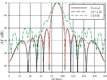
is set to −20 dB. The desired and synthesized patterns are depicted in Figure 3. In this example, the best result is obtained in the case of CFopt=2.29. For this value of CF,
the main lobe of the desired pattern and the two first SLL
for desired and synthesized patterns are matched very well. However, for the third lobe side lobe, there is a small deviation between the desired and that of the synthesized pattern, but our proposed technique provides good accuracy.
For the next example, a dual main lobe array with
d=λ/2, N=13, and SLL of −15 dB is investigated, in which the main lobes are directed toward 600 and 1200. Figure
4 shows the results of the obtained patterns using different methods. It can be seen that using our proposed method with CFopt=1.98, the desired pattern with lower
error than that of classical LSM is provided.
Figure 1. The synthesized patterns of a 26 elements uniform
array
Figure 2. The synthesized patterns of a Tschebyscheff array
Figure 3. The synthesized patterns of a Taylor array with
one parameter
Synthesizing a pulsed shaped pattern is examined as the fifth example and the results are plotted in Figure 5. The array is contained 30 elements of equally spaced with
d=0.25. It is supposed that the desired pattern provides flat-top shaped-beam in range of 75 up to 105. Also, along with the other angles, the normalized amplitude pattern has to be equal or less than 0.2. It can be seen that both methods, the proposed method, and classical LSM, present nearly the same results. For this pattern, the correction factor has to be close to that of Nyquist theorem. So, the result of our proposed method meets the results of classical LSM.
An array with a null in the broadside direction is investigated as the sixth example. This array is used in a variety of applications such as mono-pulse radar, in which null of pattern provides a very narrow angular width compared to that of the main beam. Characteristics of this array include d = 0.5 and, N=13. As it can be seen in Figure 6, the results of the proposed procedure with
CFopt = 1.98 is much better than the results of classical
LSM with CF=1. The main lobes are matched very well together. A small deviation is seen in SLL but still, the proposed method has low error compared to that of classical LSM.
An array with an asymmetrical pattern as shown in Figure 7 with d=0.75, N=17, left SLL of −25 dB and right SLL of −20 dB is investigated as the final example. It can be seen that classical LSM with CF=1 and our proposed method with CFopt=2.43 anticipate the desired
pattern very well in the region of the main lobe. However, the synthesized pattern in sidelobe regions is near to the desired pattern except for the first lobe. Moreover, classical LSM provides low accuracy for this type of array factor. It should be said that asymmetrical arrays have complex excitation.
As mentioned before, by selecting a proper value of
Figure 4. The synthesized patterns of a dual-beam array
Figure 5. The synthesized patterns of a pulse-shaped array
Figure 6. The synthesized patterns of a uniform difference
array
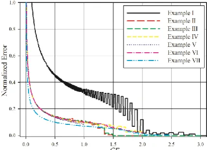
improved. To demonstrate the accuracy of the presented method, a parametric study is carried out and the normalized error of the proposed method is studied versus the correction factor. The results are plotted in Figure 8 for all presented examples in this paper. It can be seen that by increasing CF, the normalized error of solution is significantly reduced up to CFopt. However,
further increasing CF from to CFopt, the accuracy of the
synthesized pattern is not improved.
Table 1 summarize the optimum number of equations, which is required to obtain the minimum error for all the mentioned examples. It can be seen that for a few arrays the number of equations is lower than that of the number of unknown values. The required time to synthesis including the dynamic range ratio is also listed in this table for all examples.
Figure 7. The synthesized patterns of an asymmetrical array
Figure 8. The normalized error versus correction factor for
all examples
TABLE 1. The optimum number of equations, simulated time
and DRR for all investigated examples
Example # CFopt N M Time(s) DRR
1 2.61 26 31 5.02 1.0
2 1.88 19 16 1.01 69.1
3 2.29 20 14 1.29 12.04
4 1.98 13 20 1.47 45.1
5 0.97 30 48 2.80 1e3
6 1.98 13 20 0.92 27.5
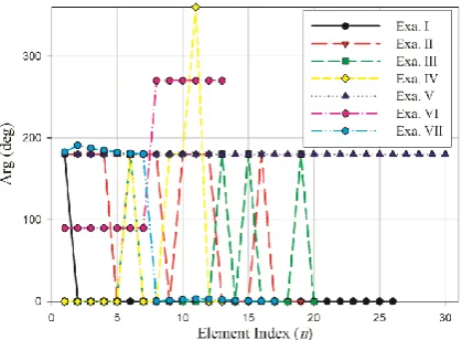
The obtained magnitude and phase values of excitation coefficients of all examples versus element index n are shown in Figures 9 and 10 respectively.
Figure 9. The obtained magnitude of an for all examples
Figure 10. The obtained phase of an for all examples
4. CONCLUSION
Equally spaced linear array antennas (ESLAs) play an important role in communication systems such as modern tracking devices and radars. The study of array pattern synthesis methods has been a traditional subject and an interesting challenge for many years. Classical LSM based on the sampled data of the desired pattern is a well-known technique to synthesize the pattern of an ELSA. Using this method, the number of sampled points of the desired pattern represents the number of equations, which determine the accuracy of the constructed pattern. To increase the accuracy of the estimated pattern with lower error than that of classical LSM, the sampling rate has to be increased leading to increase calculation complexity. In this paper, a new method based on LSM is proposed using a correction factor to minimize the error between the desired and synthesized pattern. Using the optimum
value of the correction factor CFopt would improve the
accuracy of the required pattern. A few comprehensive examples of well-known arrays are carried out to validate the accuracy of the proposed method. The obtained results demonstrate that the introduced method can be used to synthesize the array factor of equally spaced linear arrays with reasonable accuracy.
5. REFERENCES
1. Balanis, C.A., "Antenna theory: Analysis and design, John wiley & sons, (2016).
2. Udawat, A., Sharma, P. and Katiyal, S., "Optimization capabilities of lms and smi algorithm for smart antenna systems",
International Journal of Engineering- Transactions B: Applications, Vol. 26, No. 11, (2013), 1393-1400.
3. Arab, M.G. and Daryabeigi, E., "An optimal selection of induction heating capacitance by genetic algorithm considering dissipation loss caused by esr", International Journal of
Engineering- Transactions B: Applications, Vol. 24, No. 1, (2011), 19-26.
4. Ravipudi, J.L. and Neebha, M., "Synthesis of linear antenna arrays using jaya, self-adaptive jaya and chaotic jaya algorithms",
AEU-International Journal of Electronics and Communications, Vol. 92, (2018), 54-63.
5. Chatterjee, A., Mondal, T., Patanvariya, D.G. and Jagannath, R.P.K., "Fractal-based design and fabrication of low-sidelobe antenna array", AEU-International Journal of Electronics and Communications, Vol. 83, (2018), 549-557.
6. Das, A., Mandal, D., Ghoshal, S. and Kar, R., "Concentric circular antenna array synthesis for side lobe suppression using moth flame optimization", AEU-International Journal of Electronics and Communications, Vol. 86, (2018), 177-184.
7. Alijani, M.G., Neshati, M.H. and Boozari, M., "Side lobe level reduction of any type of linear equally spaced array using the method of convolution", Progress In Electromagnetics Research, Vol. 66, (2017), 79-84.
8. Wang, X., Zhou, Y. and Wang, Y., "An improved antenna array pattern synthesis method using fast fourier transforms",
International Journal of Antennas and Propagation, Vol. 2015, (2015), 1-9.
9. Wang, Y., He, X., Wang, J., Berezin, S. and Mathis, W., "Antenna array pattern synthesis via coordinate descent method", Journal of Electromagnetic Analysis and Applications, Vol. 7, No. 5, (2015), 168-177.
10. Singh, U. and Salgotra, R., "Pattern synthesis of linear antenna arrays using enhanced flower pollination algorithm",
International Journal of Antennas and Propagation, Vol. 2017, (2017), 1-11.
11. Mahanti, G.K., Pathak, N.N. and Mahanti, P.K., "Synthesis of thinned linear antenna arrays with fixed sidelobe level using real-coded genetic algorithm", Progress In Electromagnetics Research, Vol. 75, (2007), 319-328.
12. Lanza Diego, M., Perez Lopez, J.R. and Basterrechea, J., "Synthesis of planar arrays using a modified particle swarm optimization algorithm by introducing a selection operator and elitism", Progress In Electromagnetics Research, Vol. 93, (2009), 145-160.
14. Alijani, M.G. and Neshati, M.H., "Development a new array factor synthesizing technique by pattern integration and least square method", IEEE Transactions on Antennas and Propagation, Vol. 66, No. 12, (2018), 6869-6874.
15. Strang, G., Strang, G., Strang, G. and Strang, G., "Introduction to linear algebra, Wellesley-Cambridge Press Wellesley, MA, Vol. 3, (1993).
Development a New Technique Based on Least Square Method to Synthesize the
Pattern of Equally Space Linear Arrays
M. G. H. Alijani, M. H. Neshati
Electrical Engineering Department, Ferdowsi University of Mashhad, Mashhad, Iran
P A P E R I N F O
Paper history:
Received 8 May 2019
Received in revised form 19 July 2019 Accepted 12 September 2019
Keywords: Antenna Array Least Square Method Radiation Pattern Pattern Synthesis
هدیکچ
هداد زا هدافتسا هیارآ بیکرت و حرط رد لومعم شور ،زاین دروم یعشعشت یوگلا زا هدش یرادرب هنومن یاه
ساسا رب .تسا اه
سیرتام هداد یواح کیرحت بیارض نییعت یارب تاعبرم لقادح شور ،رظن دروم یعشعشت یوگلا زا هدش یرادرب هنومن یاه
هیارآ یم هدافتسا اه لومعم شور .تسا رثوم تابساحم نازیم و تقد رد هک تسا یمهم رایسب هصخشم یرادرب هنومن خرن .دوش
هنومن یطخ بیکرت زا ،تاعبرم لقادح ینییاپ تقد هک اه
یم لماش ار بیرض رتماراپ فیرعت اب ،هلاقم نیا رد .درب یم هرهب ،دوش
یریگمشچ روط هب تابساحم نازیم لاح نیع رد و هتفای شیازفا ییاهن هجیتن تقد ات تسا هدش داهنشیپ یدیدج شور ،حیحصت
ب هدش زارت یاطخ .دنکن ادیپ شیازفا ت یوگلا و بولطم یعشعشت یوگلا نی
ش ع رظن رد ینیمخت یعش تارییغت رادقم و هدش هتفرگ
اطخ رادقم ،هنیهب حیحصت بیرض یازا هب هک تسا هدش هداد ناشن .تسا هتفرگ رارق یسررب دروم حیحصت بیرض بسحرب اطخ
هنیمک یم
هیارآ زا یدادعت یارب یداهنشیپ شور .دوش هب جیاتن و هتفرگ رارق یسررب دروم هدش هتخانش یاه
جیاتن اب هدمآ تسد
زا لصاح یم هدهاشم .تسا هدش هسیاقم تاعبرم لقادح لومعم شور دروم یعشعشت یوگلا یتسرد هب یداهنشیپ شور هک دوش
.دنک یم یحارط ار ربارب لصاوف اب هیارآ یارب زاین
doi: 10.5829/ije.2019.32.11b.13