AUT J. Elec. Eng., 51(1) (2019) 55-62 DOI: 10.22060/eej.2019.14233.5213
Dynamic Performance Analysis of High-Frequency Signal Injection Based Sensorless
Methods for Application in Interior Permanent Magnet Synchronous Motors
A. R. Alaei1, J. W. Ahn2*, D. H. Lee2, S. M. Saghaeian Nejad1
1 Isfahan University of Technology, Isfahan, Iran
2 Department of Mechatronics Engineering Kyungsung University, Busan, South Korea
ABSTRACT: This paper focuses on three commonly used sensorless methods based on
high-frequency signal injection; namely, the rotating sinusoidal injection in the stationary reference frame, the pulsating sinusoidal injection in the estimated synchronous reference frame, and the pulsating square wave injection in the estimated synchronous reference frame. These methods have found applications in interior permanent magnet synchronous motor (IPMSM) sensorless drives. Some efforts have been performed to compare such high frequency signal injection-based methods from the viewpoint of some parameters such as injection frequency, voltage magnitude, etc. However, the evaluation of their dynamic seems to await further investigation and evaluation. Hence, some of the motor parameters such as pole number, machine saliency ratio, that affect the performance of the saliency-based sensorless methods are evaluated in this paper. Moreover, some such other parameters in driver circuit such as current measurement noise, the effect of time delay on demodulation, and load disturbance effect are also explored. The maximum torque per ampere (MTPA) strategy is employed to improve motor driven torque and overcome the load torque by using reluctance torque component. Finally, simulation and experimental results are used to investigate the effects of the above parameters on the performance of high-frequency signal injection based sensorless methods.
Review History:
Received: 18 March 2018 Revised: 24 November 2018 Accepted: 11 March 2019 Available Online: 11 March 2019
Keywords:
High-frequency signal injection interior permanent magnet synchronous motor maximum torque per ampere strategy position estimation
sensorless control
1- Introduction
Permanent magnet synchronous motors (PMSMs) have received much attention due to their superior advantages of high torque density per volume, performance, and reliability. Taking advantage of all the PMSM capabilities requires proper knowledge of rotor position that may be obtained from position sensors they, however, not only increase the volume, complicity, and weight of the motor-drive system but also decrease its reliability. These drawbacks motivated the development of sensorless algorithms for motor application. These algorithms may be divided into two types of standstill-low speed region methods based on the machine saliency and middle-high speed ones based on BEMF[1]. Unfortunately, BEMF based methods become useless in standstill-low speed region due to lack of BEMF in these speed values [2-8]. Instead, continuous carrier-voltage injection-based sensorless methods [9-31] are then employed due to the effectiveness at a standstill and speed range. For the zero- and low-speed position estimation, the spatial information in machine saliencies is tracked for the sensorless drive. These saliencies can be estimated through the measurement of current signals with HF voltage signal persistent excitation. It is important to note that all the signal injection techniques require a certain amount of dc-bus voltage to excite the saliency signal for the position estimation. This issue limits the saliency-based drive performance as speed increases [9]. By contrast, the position estimation based on the spatial information of back electromotive force (EMF) voltage demonstrates a comparable performance without the voltage injection when the speed is beyond 5–10% rated speed [10, 11]. Thus, it
is desired to implement two-position estimation methods at different speed areas for a full region sensorless drive. A transition algorithm combing two-position signals has developed for the smooth dynamic operation from zero to full speed [11-14].
The Saliency-based or High-frequency (HF) signal injection-based sensorless methods are basically classified according to the injection signal waveform into the sinusoidal wave injection and square wave injection methods [15, 16]. The former is further subdivided into three types of rotating signal injection in the stationary reference frame, pulsating signal injection in the estimated synchronous reference frame, and anti-clockwise pulsating injection in the estimated synchronous reference frame that rotates reversely at twice rotor electrical speed [17]. These methods may also be utilized based on negative sequence current sensing and zero-sequence voltage sensing. However, the negative zero-sequence current-based method in most cases is preferred to the zero-sequence voltage one due to the inaccessibility of the neutral point in machine windings [1, 15]. The square wave injection methods may also be divided into three types of rotating injection in the stationary reference frame, pulsating injection in the estimated synchronous reference frame, and pulsating injection in the anti-clockwise synchronous reference frame that rotates at twice rotor electrical speed [1, 4, 18, 19]. While some researchers regard the square wave injection methods to be superior to sinusoidal ones due to the enhanced bandwidth of the sensorless driver as a result of the higher injected frequency, it is yet this higher injected frequency that requires more injected voltage amplitude, which then increases the high-frequency injection losses of the motor [20]. In [17], the three commonly used high-frequency
sinusoidal injection methods are compared based on such considerations as signal delay, ease of implementation, and accuracy. Focusing on the square wave signal injection methods, [19] finds the pulsating square wave injection preferable for IPMSM sensorless drives based on current sensing.
Based on the above observations, a comprehensive understanding of the dynamic performance of HF injection methods seems to require further investigation. The present study was, therefore, designed and implemented to carry out a comprehensive comparison of HF injection-based sensorless methods considering such different parameters as machine pole number, saturation effect on machine saliency, and thereby the performance of the sensorless method. Moreover, the effects of such parameters as current measurement noise, time delay effect due to signal demodulation, and load disturbance effect are investigated. Given the greater advantages of pulsating sinusoidal injection, rotating sinusoidal injection, and pulsating square wave injection methods over the other HF signal injection based sensorless methods [4, 15, 17], the present study focuses on these three methods. To achieve these objectives, experiments and simulations were conducted and the results obtained were subjected to analysis in MATLAB.
2- Hf Signal Injection Principle
The dynamic model of an IPMSM can be described as, 0
.s sq e sd
q q
e sq s sd
d d e m
r L p L
v i
L r L p
v i
ω
ω ω ψ
+ −
= +
+
(1)
For the high-frequency injection-based sensorless methods at stand-still and low-speed regions, BEMF can be neglected and cross-coupling term is also small, thus it can also be ignored. With these assumptions, equation (1) can be simplified and presented as an inductive load circuit [7]e-[21]
0 ,
0
h h h
q q q
h h h
d d d
v X i
v X i
=
(2)
where index h denotes the “High-Frequency.”
The flux linkage equation in the stationary reference frame for the interior permanent magnet synchronous motors is captured by (3) below [22]
cos 2 sin 2
sin 2 cos 2
s s
sum diff diff
q
s s
diff sum di f
e e
e f
d
q
e d
L L L i
L L L i
θ
θ
λ
θ
θ
λ
+ −
=
− −
(3)
where .
2
d q
sum
L L
L = +
2
d q
diff
L L
L = − are average and
differential inductance, Ld and Lq are d and q-axes inductance,
.
s s
d q
i i and s. s
d q
λ λ are d and q-axes currents and fluxes in the stationary reference frame, respectively. In the estimated synchronous reference frame by using park transformation, d and q-axis currents can be driven from (3) as[23]:
( )
( )
cos (2 2 ) sin (2 2 )
sin (2 2 ) cos (2 2 )
e e
qi sum qi
e e
di di
e
r e r e qi
dif
e
r e r e di
i L v
det L
i v
v L
det L v
θ θ θ θ
θ θ θ θ
= ∫ +
− − −
∫
− −
(4)
where, e qi
v , e
di
v , e
qi
i , and e di
i are injected carrier voltages and resultant currents in the estimated synchronous d-q axes and ∫
( )
. represents the integration operator.It should be noted that equation (4) is valid for the high-frequency injection method in the standstill and low-speed regions that may be ignored in the BEMF term in motor voltage equations. Additionally, derivation of (4) from (3) is based on the assumption that stator resistance is negligible. The equation (4) is applicable to both types of interior and surface-mounted permanent magnet synchronous motors (SPMSM) while it may also be used for the square and sinusoidal shapes of injection-based sensorless methods.
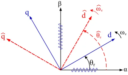
2- 1- HF rotating sinusoidal injection in the stationary reference frame
Fig. 1 shows the coordinate reference frame for the HF rotating sine injection method. Clearly, a High-frequency
sinusoidal voltage is applied to the α-β axes of the stationary
reference frame as expressed by equation (5) below.
where, wi and vi represent frequency and voltage amplitude of the injected voltage, respectively. The resultant carrier current which contains information on rotor position may be obtained using (3) as in (6) below [24]:
ia
ib
wt iah
ibh
wt Re(.)
Im(.) Im(.)
Re(.) Err
Err
θ^e
ω^e
θ^e
High Pass Filter ω^e
θ^e
Z-1 Observer
Eq.(4)
Fig. 2 Block diagram of HF rotating sinusoidal injection method
α
β
d
q
d
q
θ
rθ
eωe
ω
e2
2
( cos 2
2 .
( sin 2
,
,
2 .
i
i
j w t
i i i e
i j w t
i i i e
i
Lq Ld
i Re LPF i e v
w Ld Lq Lq Ld
i Im LPF i e v
w Ld Lq
π
π
α αβ θ
β αβ θ
− − − = = = = − (6)
where, Re(.) and Im(.) denote the real and imaginary parts of the carrier resultant current, respectively. Using such position observers as PID controller or phase loop lock (PLL), the estimated rotor position may be extracted as shown in Fig. 2.
2- 2- HF pulsating sine injection in the estimated synchronous reference frame
Fig. 3 displays the coordinate reference frame for an HF pulsating sinusoidal injection in the estimated synchronous reference frame in which the injected voltage is applied to the estimated d-axis or q-axis expressed by (7) below:
0 cos
or .
cos 0
d i i
i i
q i i
v w t
v v
v w t
=
(7)
Generally speaking, it is more popular from a torque ripple minimization viewpoint to inject the high-frequency voltage to the estimated d-axis, and the resultant current on the q-axis can be considered in estimating rotor position. The position error function that contains information on rotor position is derived by substituting (7) for (4) and performing some simplification operations to yield equation (8) below [17]
sin 2 2
q d
e q i i
q d
z z
i v
z z θ
−
= ∆
. (8)
Similar to what was observed with the rotating sine injection, rotor position and its velocity can then be tracked using a simple PID controller.
2- 3- HF pulsating square wave injection in the estimated synchronous reference frame
For the pulsating square wave injection in the estimated synchronous reference frame, the voltage injected in the estimated d-axis can be written as in (9) and shown in Fig. 4.
0 . 1 i q i i d v v v = +
(9)
By substituting (9) for (4), equation (10) is obtained as the basic equation for the square wave voltage injection method:
( )
( )
0
cos (2 2 ) sin (2 2 ) 0 . sin (2 2 ) cos ( 2
ˆ
ˆ 2
ˆ ˆ )
i
q i sum
i d
r re r re
i dif
r re r re
i v L
t det L i v L t det L
θ θ θ θ
θ θ θ θ
= + + − − − + − − (10)
Based on the square wave shape with some mathematical calculations, the high-frequency q-axis current may be written as in (11) below [23]:
( )
( )
(
)
i
i
v 1 sin . 0 ,
det / 2 2
v 1 sin
det / 2 2 ,
i dif i
q
i dif i
q i i
i
L T
i t t
L Ti
L T
i T t t T
L T
θ θ
= ∆ < <
= ∆ − < <
(11)
where Ti represents the current sampling period. Using differential processing, equation (11) may be rewritten as:
(
)
( )
0 2
1 sin . .
/ 2 2
i i i i
q q q
i dif i
T
i i t i t
v L T
det L Ti θ
∆ = = − = ≈ ∆ (12)
α
β
d
q
d
q
θ
rθ
eωe
ω
ev
diFig. 3. Coordinate reference frame for HF Pulsating sinusoidal injection in the estimated synchronous reference frame
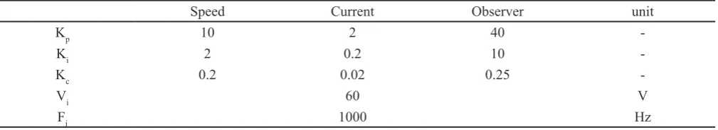
Table 1. Motor controller parameters
Speed Current Observer unit
Kp 10 2 40
-Ki 2 0.2 10
-Kc 0.2 0.02 0.25
-Vi 60 V
F 1000 Hz
α
β
d
q
d
q
θ
rθ
eωe
ω
ev
di3- Performance Analysis: Simulation And Experimental Results
In this section, evaluation of the most popular HF injection methods, i.e. rotating sinusoidal injection in the stationary reference frame, pulsating sinusoidal injection in the estimated synchronous reference frame and pulsating square wave are done. Fig. 5 depicts an overall control block diagram of the HF injection-based sensorless methods used for IPM synchronous motors. It is clear that three types of the HF injection method can be chosen depending on which coordinate reference frame or signal waveform is to be used. Rotor position and its
velocity can be estimated using equations (6), (8), and (12) in the position estimation block shown in Fig. 5. According to Table I, all the control parameters, including speed control loop and current control loop PID coefficients as well as the amplitude and frequency of the injected voltage are kept constant in all three HF injection methods in order to make reliable comparisons possible. The D-axis current reference, id*, is calculated based on the maximum torque per ampere strategy (MTPA) as in (13) below [23]:
(
)
(
)
2
* f f *2
d 2 q
d q d q
i i
2 L L 4 L L ϕ ϕ
−
= − +
− − (13)
where, 𝜑f is the magnet flux linkage.
3- 1- Motor parameters effect: Pole number effect and machine saliency ratio
Fig. 6 shows the effects of increasing motor pole number on its speed response for the rotating sinusoidal injection, pulsating sinusoidal injection, and pulsating square wave injection, respectively. It is seen that rotor position error increases when the machine pole number increases from 2 to 10, resulting in an oscillatory speed response.
It is seen that the HF rotating sine wave injection is more
0 0.5 1 1.5 2 2.5 3 3.5 4
time [sec] -10
0 10 20 30 40 50
rotor speed[rpm]
-0.5 0 0.5 1
position error[rad]
saliency ratio increasing up to unit
(a) Pulsating sine waveinjection.
0 0.5 1 1.5 2 2.5 3 3.5 4
time [sec] -10
0 10 20 30 40
rotor speed[rpm]
-0.3 -0.2 -0.1 0 0.1 0.2 0.3 0.4 0.5
position error[rad]
saliency ratio increasing up to unit
(b) Rotating sine wave injection.
0 0.5 1 1.5 2 2.5 3 3.5 4
time [sec] -100
-80 -60 -40 -20 0 20 40 60
rotor speed[rpm]
-0.2 0 0.2 0.4 0.6 0.8 1
position error[rad]
saliency ratio increasing up to unit
(c) Pulsating square wave injection.
Fig. 7. Effects of motor saturation on the performance of the sensorless method
0 0.5 1 1.5 2 2.5 3 3.5 4
time [sec]
-10 0 10 20 30 40 50
rotor speed[rpm]
-1 0 1 2 3 4
position error[rad]
pole=4 pole=6
pole=2
pole=8
(a) Square wave injection
0 0.5 1 1.5 2 2.5 3 3.5 4
time [sec] -10
0 10 20 30 40
rotor speed[rpm]
-1 0 1 2 3 4
position error[rad]
pole=4 pole=2
pole=8
pole=10
pole=6
(b) Rotating sine injection
0 0.5 1 1.5 2 2.5 3 3.5 4
time [sec]
-10 0 10 20 30 40 50
rotor speed[rpm]
-1 -0.5 0 0.5 1 1.5 2 2.5 3 3.5 4
position error[rad]
pole=8
pole=2
pole=4 pole=6
(c) Pulsating sine injection
Fig. 6. Effect of pole number on sensorless method performance
Speed Controller +
IPMSM
-Torque Current & MTPA Te*
abc LPF
iq id θ
SVPWM
VSI
ib αβ dq
αβ abc αβ dq
αβ ++
1/ p
iqi ωm*
ωm
Position estimator
e
ia +
+
+ + vα i
vβ i vdi
θe
ωe HPF
iα i iβ i
stable than the other two methods because the actual measurement currents (i.e., ia and ib) are directly used for rotor position estimation in this method. This is while, in the other two methods, the q-axis current (i.e., iq) is used for rotor position estimation which itself is obtained based on the estimated rotor position. Fig. 7 illustrates the effect of machine saturation on the performance of sensorless algorithms. Clearly, the saliency ratio approaches unity at machine saturation to nullify any differences between the values for d-axis and q-axis inductances. This is tantamount to the loss of the basic principle of the HF injection-based
sensorless methods ‒ that of machine saliency. However, as
shown in Fig. 6b, the HF rotating sine wave injection is more stable than the other two under saturation conditions.
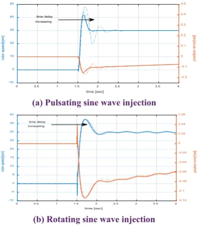
3- 2- Drive parameters: Time delay, Measurement noise, and load disturbance effect
Fig. 8 displays the effects of current measurement noise on the performance of HF injection-based sensorless methods. Based on equation (12), the rotating sinusoidal injection method is expected to be less sensitive to current measurement noise but the square wave injection one to be more sensitive due to the differential operation employed.
Fig. 9 depicts the performances of sensorless methods as a result of the time delay due to the signal demodulation process.
This process is necessary for obtaining information on rotor position in the HF injection-based sensorless method, but it causes time delays in signal processing with a consequent adverse effect on the performance of the sensorless system. To evaluate the effect of time delay, a delay of 0.8 milliseconds is added to the demodulation signal every PWM time interval up to a maximum of 4 milliseconds and the injection frequency is assumed to be 1000 Hz.
Based on the simulation results, the rotating sinusoidal injection method is more resistant than the other two methods to time-delay effects caused by signal demodulation process.
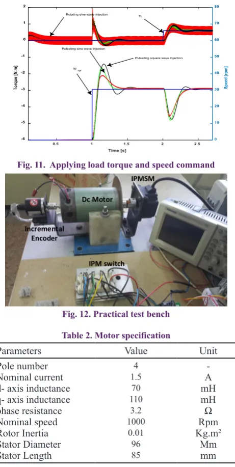
3- 3- Load disturbance effect
The effectiveness of the three famous HF injection methods under load disturbance conditions was assessed by applying a sudden load to the motor. Figs. (10a-c) present the speed response and d-q axis currents based on the MTPA algorithm when a load disturbance is applied to the motor. Fig. 11 shows the dynamic performance of the saliency-based sensorless driver for three methods when a load torque is applied. Clearly, the rotating sinusoidal injection exhibits a slower dynamic response to load disturbance than the other two methods.
0 0.5 1 1.5 2 2.5 3 3.5 4
time [sec]
-10 0 10 20 30 40 50
rotor speed[rpm]
-0.2 -0.1 0 0.1 0.2 0.3 0.4 0.5
position error[rad]
time delay increasing
(a) Pulsating sine wave injection
0 0.5 1 1.5 2 2.5 3 3.5 4
time [sec] -10
-5 0 5 10 15 20 25 30 35 40
rotor speed[rpm]
-0.12 -0.1 -0.08 -0.06 -0.04 -0.02 0 0.02 0.04 0.06
position error[rad]
time delay increasing
(b) Rotating sine wave injection
Fig. 9. Time delay increasing from 0 to 4 ms when the injected frequency is 1000 Hz.
0 0.5 1 1.5 2 2.5 3 3.5 4
time [s] -10
0 10 20 30 40 50 60
rotor speed [rpm]
square wave injection
pulsating sine injection
rotating sine injection
Fig. 8. The effect of current measurement noise on the step response of sensorless methods
0 0.5 1 1.5 2 2.5 3 3.5 4
time [s] -60
-40 -20 0 20 40 60
rotor speed [rpm]
pulsating sine injection rotating sine injection
pulsating square injection
(a) Load disturbance effect on speed response.
0 0.5 1 1.5 2 2.5 3 3.5 4
time [s] -0.4
-0.2 0 0.2 0.4 0.6 0.8 1
q-axis current [A]
pulsating square injection
rotating sine injection pulsating sine injection
(b) Q-axis current
0 0.5 1 1.5 2 2.5 3 3.5 4
time [s] -1
-0.8 -0.6 -0.4 -0.2 0 0.2
d-axis current [A]
pulsating sine injection pulsating square injection
rotating sine injection
(c) D-axis current
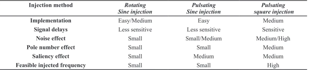
To evaluate the effectiveness of the HF rotating sinusoidal injection, a laboratory hardware test bench was constructed using the TMS320F2812 DSP board and the intelligent power module (IPM) as a Dc-Ac inverter shown in Fig. 12. The PWM frequency and the sampling frequency were both set to 10 kHz and a 310 V DC power supply was used for the inverter. The motor parameters are listed in Table 2.
The practical results, including the actual and the estimated rotor positions, speed reference, and its estimated value are shown in Figs. (13a-b) for the HF sinusoidal rotating injection when the speed direction is reversed. Fig. 13c presents the d-axis and q-axis currents of the motor compared to their reference values. As can be seen, the d-axis reference current as calculated by the MTPA algorithm is approximately zero in the no-load conditions, indicating a reluctance torque component equal to zero. When the load is applied to the motor, however, the MTPA algorithm produces a negative d-axis reference current that leads to a positive reluctance torque. This is then added to the electromagnetic torque, which increases the overall torque output and, thereby, overcomes the load torque.
Table 3 compares the results obtained in this study for the HF injection methods commonly used in IPMSM sensorless drives. It may be noted that this comparison is carried out among those HF injection methods that use the carrier current as a function of rotor position. Based on both simulation and practical results and according to the comparisons in Table I, the HF pulsating sinusoidal injection method based on current sensing techniques is observed to be more easily implemented than the rotating sinusoidal injection. However, the rotating sine injection seems to be less sensitive to such parameters as time delay due to demodulation, saturation effect due to load conditions, and motor pole number. Although sinusoidal HF injection methods are simple and easy to implement, their application is limited to lower injection frequencies due to
Incremental Encoder
Dc Motor
IPM switch IPMSM
Fig. 12. Practical test bench
0.5 1 1.5 2 2.5
Time [s] -6
-5 -4 -3 -2 -1 0 1 2
Torque [N.m]
0 10 20 30 40 50 60 70 80
Speed [rpm]
Wref
Pulsating square wave injection Pulsating sine wave injection
Rotating sine wave injection TL
Fig. 11. Applying load torque and speed command
θe
θe
ωm* ωm
Zoom in Zoom in
2π
0
50 rpm -50 rpm
(a) Estimated and actual values of rotor position and its speed.
60rpm
-60rpm
θe θe
Δθ < 0.08 rad
2π
0
(b) Estimated and actual values of rotor position and its speed when rotating direction is reversed.
-2.5A 2.5A
iq* iqe
id*
ide
Ib
Ia ,
(c) D-q axes and phases currents considering the MTPA algorithm when a sudden load is applied to the motor. Fig. 13 Experimental results for HF rotating sinusoidal
injection used in IPMSM sensorless drive Table 2. Motor specification
Parameters Value Unit
Pole number Nominal current d- axis inductance q- axis inductance phase resistance Nominal speed Rotor Inertia Stator Diameter Stator Length
4 1.5
70 110 3.2 1000
0.01 96 85
-A mH mH
Ω
Rpm Kg.m2
the PWM frequency limitation. Instead, the HF square-wave injection method can be used at higher injection frequencies, which provides such additional advantages as enhanced system bandwidth. This study, however, assumed identical frequencies for both sinusoidal and square wave injection signals in order to concentrate on the performance of HF injection methods by assuming identical values for all the control parameters and filter coefficients.
4- Conclusion
In this paper, three of the more commonly used HF injection-based sensorless methods (namely, the rotating sinusoidal injection in the stationary reference frames as well as the pulsating sinusoidal injection and the pulsating square wave injection methods in the estimated synchronous reference frame) were simulated and evaluated with respect to the parameters listed in Table II. The results obtained may be summarized as follows:
• In applications in which the motor has a higher pole number, the rotating sine injection seems to be more stable than the other two methods due to the smaller error position. It also seems to be less sensitive to either the current measurement noise or the signal delay effect due to signal demodulation.
• In applications with fast load dynamic changes, the rotating injection method seems to exhibit a slower dynamic response than the other methods; hence, either the pulsating square or the sine wave injection may be preferred. The rotating sine injection, however, exhibits a better performance under heavy load conditions that might be accompanied by saturation conditions.
• Despite their ease of implementation, rotating sine injection methods are limited in their application to lower injection frequencies. Meanwhile, the frequency of the injected signal can be easily increased in square wave injection methods by up to half the PWM frequency, which results in an enhanced control bandwidth.
5- Acknowledgments
This work was supported by the Human Resources Program in Energy Technology of the Korea Institute of Energy Technology Evaluation and Planning (KETEP) granted financial resource from the Ministry of Trade, Industry & Energy, Republic of Korea. (No.20164010200940)
References
[1] A. Ahmadreza, L. Dong-Hee, A. Jin-Woo, and N. Sayed Morteza Saghaeian, “Comparison of High Frequency
Square Wave and Sinusoidal Wave Signal Injection Methods for IPMSM Sensorless Drive Application,” (2017) 704-706.
[2] Q. Wu, T. Wang, and X. Li, “Loss-minimizing control based on QP sequence of the IPMSM drive systems for electric vehicles,” in 2017 29th Chinese Control And
Decision Conference (CCDC), (2017) 797-801.
[3] S. Amornwongpeeti, O. Kiselychnyk, J. Wang, N. Shah, and M. Soumelidis, Speed control of IPMSM motor drives using Model Reference Adaptive technique,
International Conference on Applied System Innovation
(ICASI), (2017) 672-675.
[4] F. Briz, M. W. Degner, P. Garcia, and R. D. Lorenz, Comparison of saliency-based sensorless control techniques for AC machines, IEEE Transactions on
Industry Applications, 40 (2004) 1107-1115.
[5] S. K. Sul, Y. C. Kwon, and Y. Lee, “Sensorless control of IPMSM for last 10 years and next 5 years,” CES
Transactions on Electrical Machines and Systems, 1
(2017) 91-99.
[6] M. Linke, R. Kennel, and J. Holtz, “Sensorless speed and position control of synchronous machines using alternating carrier injection,” in Electric Machines
and Drives Conference, 2003. IEMDC’ 03. IEEE
International, (2003) 1211-1217 vol.2.
[7] Y. C. Kwon and S. K. Sul, “Reduction of Injection Voltage in Signal Injection Sensorless Drives Using a Capacitor-Integrated Inverter,” IEEE Transactions on Power Electronics, 32 (2017) 6261-6274.
[8] S. Kim and S. K. Sul, Sensorless control of AC motor — Where are we now, International Conference
on Electrical Machines and Systems, (2011) 1-6.
[9] S. Yang and Y. Hsu, Full Speed Region Sensorless Drive of Permanent-Magnet Machine Combining Saliency-Based and Back-EMF-Saliency-Based Drive, IEEE Transactions
on Industrial Electronics, 64 (2017) 1092-1101.
[10] N. Matsui, Sensorless PM brushless DC motor drives, IEEE Transactions on Industrial Electronics, 43 (1996) 300-308, 1996.
[11] T. Bernardes, V. F. Montagner, H. A. Gründling, and H. Pinheiro, Discrete-Time Sliding Mode Observer for Sensorless Vector Control of Permanent Magnet Synchronous Machine, IEEE Transactions on Industrial
Electronics, 61 (2014) 1679-1691.
[12] J. Hong, S. Jung, and K. Nam, An incorporation method of sensorless algorithms: Signal injection and back EMF based methods, International Power Electronics Table 3. Comparison of HF injection-based sensorless methods
Injection method Rotating
Sine injection Sine injectionPulsating square injection Pulsating
Implementation Easy/Medium Easy Medium
Signal delays Less sensitive Less sensitive Sensitive
Noise effect Small Small/Medium Medium/High
Pole number effect Small Small Medium
Saliency effect Small Medium Medium
Conference - ECCE ASIA (2010) 2743-2747.
[13] K. Ide, H. Jung-Ik, and M. Sawamura, A hybrid speed estimator of flux observer for induction motor drives,
IEEE Transactions on Industrial Electronics, 53 (2006)
130-137.
[14] W. T. Villet, M. J. Kamper, P. Landsmann, and R. Kennel, Hybrid position sensorless vector control of a reluctance synchronous machine through the entire speed range,” 15th International Power Electronics and Motion Control Conference (EPE/PEMC), (2012) LS4b-1.1-1-LS4b-1.1-7.
[15] A. Alaei, D.-H. Lee, J.-W. Ahn, and S. M. S. Nejad, “Comparisons of The High Frequency Signal Injection Algorithms for PMSM Sensorless Drive,” KIEE (2017) 12-15.
[16] A. Alaei, D.-H. Lee, J.-W. Ahn, and S. M. S. Nejad, “Comparison of High Frequency Square Wave and Sinusoidal Wave Signal Injection Methods for IPMSM Sensorless Drive Application,” 대한전기학회 학술대회 논문집, (2017) 704-706.
[17] P. L. Xu and Z. Q. Zhu, “Comparison of carrier signal injection methods for sensorless control of PMSM drives,” IEEE Energy Conversion Congress and
Exposition (ECCE), (2015) 5616-56
[18] Y. D. Yoon, S. K. Sul, S. Morimoto, and K. Ide, “High-Bandwidth Sensorless Algorithm for AC Machines Based on Square-Wave-Type Voltage Injection,” IEEE
Transactions on Industry Applications, 47 (2011)
1361-1370.
[19] P. L. Xu and Z. Q. Zhu, “Novel Square-Wave Signal Injection Method Using Zero-Sequence Voltage for Sensorless Control of PMSM Drives,” IEEE Transactions
on Industrial Electronics, 63 (2016) 7444-7454.
[20] G. Xie, K. Lu, S. K. Dwivedi, J. R. Rosholm, and F. Blaabjerg, “Minimum-Voltage Vector Injection Method for Sensorless Control of PMSM for Low-Speed Operations,” IEEE Transactions on Power Electronics, 31 (2016) 1785-1794, 2016.
[21] Z. Yue, Z. Zhe, M. Cong, W. Qiao, and Q. Liyan, “Sensorless control of surface-mounted permanent-magnet synchronous machines for low-speed operation based on high-frequency square-wave voltage injection,”
IEEE Industry Applications Society Annual Meeting,
(2013) 1-8
[22] C. Zhiqian, M. Tomita, S. Doki, and S. Okuma, “An extended electromotive force model for sensorless control of interior permanent-magnet synchronous motors,” IEEE Transactions on Industrial Electronics,
50 (2003) 288-295.
[23] A. Alaei, D.-H. Lee, J.-W. Ahn, and S. M. S. Nejad, “Sensorless Control of IPMSM with a Simplified High-Frequency Square Wave Injection Method.”
[24] J. M. Liu and Z. Q. Zhu, “Novel Sensorless Control Strategy With Injection of High-Frequency Pulsating Carrier Signal Into Stationary Reference Frame,” IEEE
Transactions on Industry Applications, 50 (2014)
2574-2583.
Pleasecitethisarticleusing:
A. R. Alaei, J. W. Ahn, D. H. Lee, S. M. Saghaeian Nejad, Dynamic Performance Analysis of High-Frequency Signal Injection Based Sensorless Methods for Application in Interior Permanent Magnet Synchronous Motors, AUT J. Elec. Eng., 51(1) (2019) 55-62.