AIJ-EEE) )
٭
Corresponding Author, Email: [email protected]
Vol. 44, No. 2, Fall 2012 21
Magnetic Saturation Impacts on Fault Analysis
of Squirrel- Cage Induction Motors Using Winding
Function Approach
M. Ojaghi
1*, M. Sabouri
21- Assistant Professor, Department of Electrical Engineering, University of Zanjan, Zanjan, Iran 2- PhD. Student, Department of Electrical Engineering, University of Zanjan, Zanjan, Iran
ABSTRACT
Multiple coupled circuit modeling of squirrel-cage induction motors, or winding function approach is the
most detailed and complete analytical model used to analyze the performance of the faulty induction motors.
This paper extends the above-mentioned model to a fully developed saturable model. This model includes
variable degrees of the saturation effects using both an appropriate air gap function and novel techniques for
locating the angular position of the air gap flux density and for estimating the saturation factor. Comparing
simulated and experimental magnetization characteristics as well as no-load current waveforms, accuracy of
the new saturable model is verified. Using saturable and non-saturable models, various simulations are
carried out on faulty induction motors, and then, by comparing the results, the impacts of the saturation on
the performance of the faulty motor become evident. Furthermore, comparisons are made with the
experimental and/or finite elements results to reflect better accuracy of the saturable model versus
non-saturable model.
KEYWORDS
Amirkabir International Journal of Science& Research (Electrical & Electronics Engineering)
(AIJ-EEE)
M. Ojaghi& M.Sabouri
22 Vol. 44, No. 2, Fall 2012
1-INTRODUCTION
For economic utilization of the magnetic material, electrical machines operating regions have to be extended above the knee of the magnetization characteristics that which forces the machine into saturation. Therefore, many attempts have been made to include saturation effects in the squirrel-cage induction machine (SCIM) models [1]–[5]. The multiple coupled circuits model (MCCM) of SCIM, based on the winding function theory [4]-[8] is one of these models. MCCM has gained a wide application in the analysis of SCIM, mainly due to its ability to analyze faulty machines. Such analysis helps us realize the faulty SCIM’s performance to extract proper indices for the various faults and to develop effective fault diagnosis and condition monitoring techniques for SCIMs. To do so, MCCM must be as accurate as possible though ignoring the magnetic saturation may keep it away from the required exactness [9]-[10]. Therefore, it is reasonable to include properly the saturation effect to MCCM and to study the accuracy improvement.
An extension to MCCM, which includes variable degrees of saturation effects, has been reported in [5]. A saturable MCCM (SMCCM) needs to track the air gap rotating flux density, and this has been done by a rather simple technique in [5]. However, application of this technique may lead to a wrong result if the air gap flux distribution is distorted. As it will be clear in the paper, many SCIM faults cause the air gap flux density to be disturbed. Thus, the existing SMCCM is not viable to analyze the faulty SCIMs. In addition, the saturation factor (Ksat) has been determined using air gap voltage fundamental harmonic amplitude [5], which depends on the rotation speed of the air gap flux density as well as its amplitude, while the saturation degree depends only on the flux density amplitude.
In this paper, flux-linkages of the rotor meshes, which are calculated in every simulation step, are used to estimate the air gap flux density distribution around the air gap. Then, Fourier series analysis is used to determine the space harmonics of the air gap flux density, including fundamental harmonic amplitude (B1) and its phase angle (α1). B1 is used to determine Ksat properly and α1 is utilized to track the air gap flux density. Therefore, a modified version of SMCCM is obtained in a way that its accuracy is proved by comparing the no-load current waveforms and magnetization characteristics determined through simulation and experiments. Then, using both the modified SMCCM and the normal MCCM, the performance of some faulty CIMs are simulated. By comparing the results, impacts of magnetic saturation on the faulty SCIM’s performance and their fault indices will be clear. Comparisons are also made by experimental and/or finite elements results to approve the higher accuracy of the proposed SMCCM.
2-SATURABLEMULTIPLECOUPLEDCIRCUIT
MODELOFSCIM
Dynamic equations for the Δ-connected SCIM based on MCCM has been well defined in [6], where a technique to evaluate the effects of the rotor bars skewing
was also presented. This modified winding function made the equations applicable for the non-uniform air gap machines [7]. This way, the equations are valid when studying the SCIM performance with the rotor faults such as broken rotor bars and end ring. The only modification required is to increase sufficiently the resistance of the broken elements. However, when studying the SCIM performance with the stator faults such as interturn fault, the shorted turns are normally considered as the 4th phase (phase ‘d’) of the stator and thus, more essential modifications are required. Considering a Y-connected SCIM with interturn fault in the stator phase 'a' and using line-to-line voltages, the dynamic equations could be written as follows [11]
] [ ] ][ [ ] [ sll dt d sll I sll R sll
V (1) ] [ ] ][ [ ] 0 [ r dt d r I r
R
(2)
dt d J L T e
T (3) where: T bc v ab v sll
V ] [ 0]
[ (4) T d i b i a i sll
I ] [ ]
[ (5) T
i i i
Ir] [ ... R]
[ 1 2 (6) ] ][ [ ] ][ [ ]
[
sll Lssll Isll Lsrll Ir (7) ] ][ [ ] ][ [ ][
r Lrsll Isll Lrr Ir (8) Td bc ab
sll] [ ]
[ (9) T
R
r] [ ... ]
[ 1 2 (10)
d R c R b R c R b R a R sll R 0 0 0 0 ]
[ (11)
dr cr br cr ar srll L L L L L L ]
[ (12)
Tsrll rsll L L ]
[ (13) In (9), ψab=ψa-ψb and ψbc=ψb-ψc. Also in (12) Lar, Lbr, Lcr and Ldr are vectors containing mutual inductances between the specified stator winding and all rotor meshes. Taking µ=0, the equations are valid for the healthy SCIM. A technique to evaluate the effects of the rotor bars skewing given in [6] is applicable here.
As can be seen, various self/mutual inductances of the stator phases and/or the rotor meshes and their derivatives versus the rotor position are the most important
parameters of the dynamic equations based on MCCM. According to the winding function or modified windi
Vol. 44, No. 2, Fall 2012 23 ) ( 2 0 ) ( 2 0 0 ) ( 2 0 ) ( 2 ] [ re R rb R rb R re R rb R rb R rb R re R rb R rb R rb R rb R re R rb R Rr (14)
)
(
2
3
2
1
31
2
23
)
(
2
22
21
1
13
12
)
(
2
11
]
[e
l
b
l
RR
L
R
L
R
L
b
l
R
L
L
R
L
b
l
L
e
l
b
l
L
b
l
L
b
l
R
L
L
b
l
L
e
l
b
l
L
rr
L
(15)
ls
l
dd
L
cd
L
bd
L
cd
L
ad
L
cd
L
bd
L
ls
l
cc
L
bc
L
bc
L
ls
l
bb
L
ls
l
cc
L
ca
L
bc
L
ab
L
bd
L
ad
L
bc
L
ls
l
bb
L
ca
L
ab
L
bc
L
ab
L
ca
L
ls
l
aa
L
ssll
L
)
1
(
]
[
(16)]
[
]
[
]
[
2
1
]
[
]
[
]
[
2
1
]
[
]
[
]
[
2
1
]
[
]
[
]
[
2
1
r r rr T r sll r rsll T r r r srll T sll sll r sll T sll eI
L
I
I
L
I
I
L
I
I
L
I
T
(17)
2
0
1
d
y
N
x
n
g
l
r
o
xy
L
(18)any mesh of the rotor (1 to R). In the case of the uniform air gap machine, Ny is the winding function of the y circuit, while in the case of the non-uniform air gap machine, it is the modified winding function of the y circuit. In the latter case, the modified winding function guarantees the equality: Lxy=Lyx for any x and y circuits [7].
Saturation of the magnetic material causes its reluctance to be increased against the machine's flux. Similar increase of the reluctance can be achieved by a proportional increase in the air gap length along the main flux path [4]-[5]. Anywhere within the core material, the
reluctance increase due to the saturation depends on the exact value of the flux density independent of the flux direction. It is expected that the fictitious air gap length fluctuates a complete cycle every half cycle of the air gap flux density distribution around the air gap. Assuming a sinusoidal form for this fluctuation, the following satisfies the aforementioned requirements [5]:
))] ( 2 cos( 1 [ f
s g P
Amirkabir International Journal of Science& Research (Electrical & Electronics Engineering)
(AIJ-EEE)
M. Ojaghi& M. Sabouri
24 Vol. 44, No. 2, Fall 2012
where g' and ρ are determined as: 2 3 0 sat sat K K g
g (20)
sat sat K K 3 ) 1 ( 2
(21)
The saturation factor (Ksat) is defined as the ratio of the fundamental components of the air gap voltage for the saturated and unsaturated conditions [4]-[5].
Based on using the modified winding function theory and assuming that turn functions have only step variations in the center of the slots, exact analytic equations can be obtained for various inductances by using the inverse of (19) in (18) and determining the indefinite integral. Then, differentiating the equations with respect to the rotor position (θr), exact analytic equations are also obtained for the derivatives of the inductances. The equations are functions of Ksat and φf. Therefore, a variable degree of saturation effect enters to the SCIM dynamic model. Complete details of the equations are given in [5]. These equations are equally applicable when estimating the inductances and their derivatives are to be used in the dynamic model given in [6] for Δ–connected SCIM.
3-DETERMININGKSAT ANDOFINFAULTY
SCIM
Generally, the air gap flux density distribution is disturbed in the faulty SCIMs and this leads to an error in the use of the technique for determining φf [5]. In addition, Ksat is determined using the air gap voltage depending both on the rotation speed of the air gap flux and its amplitude while the saturation degree depends only on the flux density amplitude. This causes some difficulty when applying the model for variable-speed drive systems, as the air gap voltage before satuartion is no more a constant, but varies by the reference speed variation. The aim of this section is to resolve these problems.
When simulating a SCIM using MCCM or SMCCM, flux-linkages of all the rotor meshes should be evaluated within the simulation steps. According to (8), these flux linkages have contributions from all the stator phases and rotor meshes. Since any rotor mesh consists of only one turn, these flux-linkages are the total fluxes passing through the meshes. Considering the short air gap length and ignoring the flux leakages, the air gap flux density next to any rotor mesh i can be estimated as:
A
Baii (22) where A is the area next to the mesh in the air gap:
R rl
A2 (23) Therefore, the air gap flux density distribution is estimated within any simulation step. Then, using Fourier series analysis, the space harmonics of the air gap flux density is determined by the following equations:
] ) cos( ) [cos( 1 ) sin( 1 ) sin( ) ( 1 1 1 1 2 0 1
R i i i ai R i i sn nP nP B np d nP B d nP B B i i (24)
R i i i i R i ai cn nP nP B np d nP B d nP B B i i 1 1 1 2 0 )] sin( ) [sin( 1 ) cos( 1 ) cos( ) ( 1 1 (25)Then, the phase angle and amplitude of the space harmonics are calculated as:
) ( tan 1 cn sn n B B
(26)
2 2
sn cn
n B B
B (27) Use (22) to determine the air gap flux density distribution of a SCIM with two broken rotor bars at a simulation step and then use (24)-(27) to calculate its fundamental space harmonic, Fig. 1 shows the results where distortion of the flux density due to the fault is obvious. Having the phase angle of the fundamental harmonic, φf could be estimated by
P P r f 2 1
(28) Furthermore, using the amplitude of the fundamental harmonic, Ksatis obtained as:
0 1 B B
Ksat (29)
where B0is related to the knee-point flux density (Bkp) of the core material within the teeth as:
t kp
w w B
B0 (30) These modifications in φf and Ksat estimations make SMCCM applicable to the simulation of various faulty SCIMs connected to the main or variable-speed drives.
Vol. 44, No. 2, Fall 2012 25 Figure 1: Estimated air gap flux density (__) and its
fundamental space harmonic (---) for a SCIM with two broken rotor bars.
4-EXPERIMENTALTESTRIGS
Two different test rigs were used to provide the experimental results. The first one consists of an 11kW, 380V, 50Hz, 4-poles, the Δ-connected SCIM (SCIM I) mechanically coupled with a DC generator, while a variable resistor bank connected to the terminals of the generator. The load of the generator and consequently SCIM could be adjusted by varying the resistance of the resistor bank and/or by regulating the excitation current of the generator. A PC equipped with a data acquisition (DAQ) card type PCI- 1710HG is used for sampling the required electrical data at a certain adjustable frequency [12]. An additional rotor with broken bars was provided to do experiments under the rotor broken bar conditions. The required number of adjacent bars was broken by drilling on them. The experimental results related to the SCIM with broken rotor bars captured by using this test rig. The second test rig consists of a 750W, 380V, 50Hz, 2-poles, Y-connected SCIM (SCIM II) mechanically coupled with a magnetic powder brake as an adjustable mechanical load. Three-phase windings of the stator of SCIM are removed and replaced by similar windings with various taps taken out from different turns of one of the windings (phase 'a' winding). Interturn fault with variable number of shorted turns is produced in SCIM by connecting any two of the taps. A digital scope-meter type Fluke 199C is used for sampling the line currents of SCIM [13]. Experimental results related to the SCIM with interturn faults are captured by using this test rig. Fig. 4 shows a photograph of both test rigs.
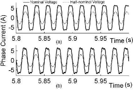
Figure 2: No-load phase current of the healthy SCIM I with nominal (__) and half-nominal (---) stator voltages: a) simulation using the SMCCM model, b) experimental data
Figure 3: Stator line voltage versus no-load current (magnetization curve) obtained by simulation using the
SMCCM (__) and experiment (×).
Figure 4: The photograph of the first test rig (top) and the second test rig (bottom)
SCIMPERFORMANCEDUETOMAGNETIC
SATURATIONUNDERBROKENROTORBARS
Many kinds of stresses on a SCIM may lead to the rotorbars breakage, including thermal stresses, magnetic stresses, residual stresses, dynamic stresses, environmental stresses and mechanical stresses [14]. 5% -10% of total SCIMs failures are due to the rotor faults and considerable research reports aiming at diagnosis of these faults are available in the literature [14]-[15]. Here, the SCIM performance under broken rotor bars is studied using SMCCM and compared to those obtained by MCCM, so that the magnetic saturation effect on the performance will be clear.
Amirkabir International Journal of Science& Research (Electrical & Electronics Engineering)
(AIJ-EEE)
M. Ojaghi& M. Sabouri
26 Vol. 44, No. 2, Fall 2012
the air gap flux density obtained by both SMCCM and MCCM. It must be noticed that the three curves in each chart of the figure are not synchronized, since they obtained from different simulation processes on SCIM I. As seen, the rotor bar breakage has increased the amplitude fluctuation of the 3rd space harmonic of the air gap flux density (especially with two broken bars). Also, the clear effect of saturation on the behavior of this harmonic amplitude in the healthy and faulty SCIMs is noticeable. Due to the saturation, normal tedious variation of the harmonic amplitude was disturbed and its maximum value was increased. The SMCCM results in Fig. 5 are qualitatively in agreement with the corresponding experimental results [16].
Fig. 6 shows the rotor teeth flux densities determined by a manner described in Section III assuming that the total flux passing through the any rotor mesh concentrated uniformly in the relevant rotor tooth. As observed, a broken rotor bar reduces the flux of an adjacent tooth and considerably increases the flux of other adjacent tooth. This leads to a higher local saturation in the later tooth. Saturation effect on the teeth flux densities is obvious in the figure and is in agreement with the similar finite elements results [17].
Representing a broken bar with zero current as the superposition of a healthy bar and a current source injecting a current in the bar of opposite value as the current flowing in the healthy bar, and using an approach based on the rotating magnetic fields, it could be realized that the bar breakage induces currents at frequencies (1±2s)f in the stator windings, where f is the supply fundamental frequency [14]-[17]. These frequency components (sidebands) are the main signatures of the broken rotor bar fault in the stator currents, which are generally used as indices for the fault diagnosis.
To verify the saturation impact on the sidebands, the normalized frequency spectra of the stator line current are shown in Fig. 7 for the healthy SCIM I and the SCIM with two broken bars under 50% of the rated load. Comparison can be made between the results obtained through simulation using MCCM and SMCCM with that of the experiments.
Figure 5: Amplitude variation of the 3rd space harmonic of the air gap flux density obtained by: a) the SMCCM and b) the MCCM.
Figure 6: Estimated rotor teeth flux densities in healthy (---) and 1 broken bar (__) SCIMs obtained by simulation using: a) the SMCCM and b) the MCCM.
As seen, the sidebands are clear in the spectra and their amplitudes are amplified due to the fault. Also, the amplitudes of the harmonics in the SMCCM results are very close to those of the experimental results. This implies that SMCCM is more reasonable to analyze the SCIM with broken rotor bars than the MCCM model. It seems that the increased asymmetry due to the non-uniform effect of the magnetic saturation is the cause for the increase of the sidebands amplitudes in the experimental as well as the SMCCM results. Such increase due to the saturation has been predicted in the previous studies [15]. The sidebands are also visible in the healthy SCIM both in the simulation and experimental results. This is partially due to the saturation and partially due to the rotor bars skewing, as eliminating the skewing effect from the healthy MCCM, in turn eliminates the sidebands.
Coil to ground fault.
Vol. 44, No. 2, Fall 2012 27
An open circuit fault in SCIM is first considered in this section, where a complete coil of the phase 'c' winding is considered to be open-circuited, while the other coil of the winding remains connected. Then, the performance of the faulty SCIM is studied by simulations using both SMCCM and MCCM. The study confirms that the fault disturbs the air gap flux density distribution. Fig. 8 shows the third space harmonic of the air gap flux density in the healthy and faulty SCIM at one step of the simulation. As seen, the harmonic amplitude has been amplified due to the fault, while the magnetic saturation, introduced by SMCCM, intensified this considerably. Fig. 9 shows the rotor teeth flux densities in the healthy and faulty SCIMs. The rotor teeth with the higher flux densities experience increased fluxes due to the fault, while the saturation effect, introduced by SMCCM, limits such increased flux densities.
Figure 8: Third space harmonic of the air gap flux density in the healthy (---) and the phase 'c' coil open-circuited (__) SCIM obtained by simulation using: a) the SMCCM and b) the MCCM.
Figure 9: The estimated rotor teeth flux densities in the healthy (---) and the phase 'c' coil open-circuited (__) SCIM obtained by the simulation using: a) the SMCCM and b) the MCCM.
In the second case a stator winding turn-to-turn fault is considered within the SCIM II. Generally, this fault is the initial cause of the other stator faults [18]; therefore, it was appreciated by enormous research studies in the past [14]-[15], [19]-[23]. Considering the fault to be in the
phase 'a', the methods in (1)-(17) as well as the analytic equations given in [5] for the inductances and their derivatives could be used to simulate the performance of the faulty SCIM. Therefore, the shorted turns of the stator phase are considered as the fourth phase (phase ‘d’) with zero voltage in the SCIM equations [22]. Fig. 10 shows the turn functions of the phase 'a' before and after the fault occurrence with 14 shorted turns as well as the turn function of the phase 'd' after the fault occurrence. Fig. 11 shows the variations of the self inductance of the phase 'd' (Ldd) by the variations of Ksat and φf. By increasing Ksat,
Ldd fluctuates increasingly around its decreasing mean value. The increase of g' and ρ by increasing Ksat are respectively the reasons for the decreasing mean value and increasing fluctuations of the inductance. A complete rotation of φf causes two complete cycles of variation for
Ldd due to the two poles of the SCIM.
Figure 10: The turn functions of the phase 'a' winding: a) before and b) after the turn-to-turn fault with 14 shorted turns in the outer coil and c) the turn function of the phase 'd' after the fault occurrence
Figure 11: Phase 'd' self inductance (Ldd) variation versus Ksat and φf
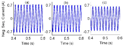
Figure 12: The stator negative sequence current obtained by a) Experiment, and simulation using: b) the SMCCM and c) the MCCM in the faulty SCIM II with 21 shorted turns under full-load.
Amirkabir International Journal of Science& Research (Electrical & Electronics Engineering)
(AIJ-EEE)
M. Ojaghi& M. Sabouri
28 Vol. 44, No. 2, Fall 2012
the old indices introduced to diagnose this fault [15], [19]. In the healthy symmetrical SCIM with the balanced three-phase supply, negative-sequence current is zero. The amount of the current can quickly be increased by the turn-to-turn fault. For the SCIM II with 21 turns shorted in phase 'a' winding under the full load, the negative- sequence currents obtained through the simulation and experiments are shown in Fig. 12. As seen, the saturation effect, introduced by SMCCM causes the amplitude of the current to increase and to get closer to the experimental results. Thus, it can be realized that SMCCM gives a more exact model for the faulty SCIMs compared to MCCM. To plot the negative sequence current waveforms, the stator line current phasors are first obtained by using the sampled currents and any algorithm which is conventional in the field of the digital protection [24]. Then, using the line current phasors, the negative sequence current phasor is determined [15]. Knowing the amplitude, phase angle and frequency of the negative sequence current, its waveform could be easily sketched.
Simulations and experiments on the SCIM II with 14 and 21 shorted turns were repeated under various load levels. Table I compares the attained amplitudes of the stator negative sequence current. As observed, the negative sequence current increases by increasing the fault degree, where the load level change has a little impact (about 5%) on the current. Also, the SMCCM results follow the experimental results more closely in comparison with the MCCM results.
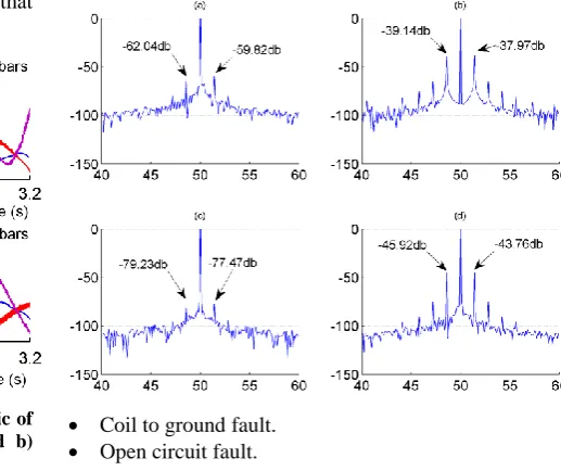
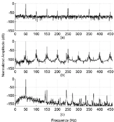
The other index introduced to diagnose the turn-to-turn fault is the amplitude of the 3rd harmonic of the stator line current [22], [25]. Fig. 13 shows the normalized spectra of the stator line current under no load for the SCIM II with 21 shorted turns. As seen, the 3rd harmonic amplitude obtained from SMCCM is very close to that obtained experimentally. In the experimental spectrum, all the even/odd harmonics are present, which are also present in the SMCCM result but not in the MCCM result. The presence of the 3rd harmonic current due to the turn-to-turn fault was also reported in the experimental results in [26].
Figure 13: The normalized spectra of the stator line current under no load for the SCIM II with 21 shorted turns: a) Experimental, b) SMCCM and c) MCCM
Table II compares the normalized amplitudes of the 3rd harmonic current for the SCIM II with 14 and 21 shorted turns under various load levels. As seen, the SMCCM results follow the experimental results more closely in comparison with the MCCM results, although, the SMCCM results gradually keep away from the experimental results as the load increases.
7-CONCLUSION
Vol. 44, No. 2, Fall 2012 29 TABLE.I.THE AMPLITUDE OF THE STATOR NEGATIVE SEQUENCE CURRENT UNDER VARIOUS LOAD LEVELS
The faulty SCIM II with 14 shorted turns The faulty SCIM II with 21 shorted turns
No load
20% of rated
load
40% of rated
load
60% of rated
load
80% of rated
load
Full load
No load
20% of rated
load
40% of rated
load
60% of rated load
80% of rated
load Full load
Experimental
(A) 0.470 0.478 0.481 0.482 0.489 0.494 0.698 0.690 0.690 0.712 0.726 0.730 SMCCM (A) 0.467 0.490 0.480 0.456 0.462 0.487 0.693 0.700 0.668 0.701 0.702 0.702
MCCM (A) 0.413 0.457 0.438 0.411 0.422 0.430 0.619 0.623 0.609 0.647 0.648 0.650
TABLE II.NORMALIZED AMPLITUDE OF THE THIRD HARMONIC CURRENT OF THE STATOR UNDER VARIOUS LOAD LEVELS
The faulty SCIM II with 14 shorted turns The faulty SCIM II with 21 shorted turns
No load
20% of rated load
40% of rated
load
60% of rated
load
80% of rated
load
Full load
No load
20% of rated
load
40% of rated
load
60% of rated
load
80% of rated
load Full load
Experimental
(db) -27.96 -27.71 -27.83 -27.37 -28.31 -29.22 -28.35 -28.52 -28.92 -28.35 -29.43
-29.90 SMCCM (db) -31.55 -32.58 -34.18 -36.02 -37.15 -39.14 -29.83 -30.37 -31.46 -33.26
-34.96 -36.70
MCCM (db) -63.18 -63.18 -66.33 -74.01 -66.84 -66.75 -66.04 -64.27 -64.82 -66.22 -67.20
-68.24
8-
N
OMENCLATUREBai air gap flux density next to any rotor mesh i
Bsn sine component of nth space harmonic of the air gap flux density
Bcn cosine component of nth space harmonic of the air gap flux density
B1 amplitude of the space fundamental harmonic of the air gap flux density
B0 air gap flux density corresponding to the knee-point flux density within the teethes
g-1 inverse air gap function
gs fictitious air gap function in the presence of saturation
g' mean value of gs
g0 effective air gap length of the unsaturated machine
ia , ib stator phase currents
id current of the shorted turns in the stator
ik current of the rotor mesh k , k=1, 2, …, R
J inertia moment of the rotor and mechanical load Ksat saturation factor
l stack length
lb leakage inductance of the rotor bars
le leakage inductance of the rotor end ring between two adjacent bars
lls leakage inductance of the stator phases
Lii self inductance of the circuit i
Lij mutual inductance between the circuits i and j
nx turn function of the x phase (mesh)
Ny winding function or modified winding function of the y phase (mesh)
P machine's pole pairs
R number of rotor bars (meshes) Ra resistance of the stator phase ‘a’
Rb resistance of the stator phase ‘b’
Rc resistance of the stator phase ‘c’
Rd resistance of the shorted turns in the stator
Rrb resistance of the rotor bars
Rre resistance of the rotor end ring between two adjacent bars
r air gap mean radius
Amirkabir International Journal of Science& Research (Electrical & Electronics Engineering)
(AIJ-EEE)
M.Ojaghi& M. Sabouri
30 Vol. 44, No. 2, Fall 2012
Te induced torque
TL load torque
vab ,
vbc
stator line-to-line voltages w slot pitch
wt tooth width
α angle in the rotor reference frame
α1 phase angle of the space fundamental harmonic of the air gap flux density
αx, αy angle of the center of the rotor bars x and y
φ angle in the stator stationary reference frame φf angular position of a zero crossing point of the
air gap flux density
μ0 the air magnetic permeability
μ ratio of the number of shorted turns to the number of total turns of a stator phase winding θr rotor angular position
ρ peak value of the air gap length fluctuation s synchronous speed
rotor speed
ψa flux linkages of the stator phase ‘a’
ψb flux linkages of the stator phase ‘b’
ψc flux linkages of the stator phase ‘c’
ψd flux linkages of the shorted turns in the stator
ψk flux linkages of the rotor mesh k , k=1, 2, …, R
9-REFERENCES
[1] D. Bispo, L. M. Neto, J. T. Resende and D. A. Andrade, “A new strategy for induction machine modeling taking into account the magnetic saturation”, IEEE Trans. Ind. Applications, vol. 37, no. 6, pp. 1710 - 1719, Nov./Dec, 2001.
[2] T. Tuovinen, M. Hinkkanen, and J. Luomi, “Modeling of saturation due to main and leakage fux interaction in induction machines”, IEEE Trans. Ind. Applications, vol. 46, no. 3, pp. 937 - 945, 2010.
[3] Tu Xiaoping, L.-A. Dessaint, R. Champagne, and K. Al-Haddad, “Transient modeling of squirrel-cage induction machine considering air-gap flux saturation harmonics”, IEEE Trans. Ind. Electronics, vol. 55, no. 7, pp. 2798 - 2809, 2008. [4] S. Nandi, “A detailed model of induction machines
with saturation extendable for fault analysis”, IEEE Trans. Ind. Applications, vol. 40, pp. 1302 - 1309, September/October, 2004.
[5] M. Ojaghi and J. Faiz, “Extension to multiple coupled circuit modeling of induction machines to include variable degrees of saturation effects”, IEEE Trans. Magn., vol. 44, no. 11, pp. 4053- 4056, Nov, 2008.
[6] G. M. Joksimovic, M. D. Durovic, J. Penman, and N. Arthur, “Dynamic simulation of dynamic eccentricity in induction machines-finding function approach”, IEEE Trans. Energy Conversion, vol. 15, pp. 143 - 148, June, 2000.
[7] J. Faiz and I. Tabatabaei, “Extension of winding function theory for nonuniform air gap in electric machinery”, IEEE Trans. Magn., vol. 38, pp. 3654-3657, November, 2002.
[8] J. Faiz and M. Ojaghi, “Unified Winding Function Approach for Dynamic Simulation of Different Eccentricity Faults in Cage Induction Machines”, IET Electr. Power Appl., vol. 3, no. 5, pp. 461-470, Set./Oct, 2009.
[9] S. Nandi, “Detection of stator faults in induction machines using residual saturation harmonics”, IEEE Trans. Ind. Applications, vol. 42, no. 5, pp. 1201- 1208, 2006.
[10] Faiz, B. M. Ebrahimi, and H. A. Toliyat, “Effect of magnetic saturation on static and mixed eccentricity fault diagnosis in induction motor”, IEEE Trans. Magn., vol. 45, no. 8, pp. 3137 - 3144, 2009.
[11] A Raie, and V. Rashtchi, “Using a genetic algorithm for detection and magnitude determination of turn faults in an induction motor” ,Springer- Verlag Electrical Engineering, vol. 84, pp. 275- 279, August, 2002.
[12] PCI-1710 User's Manual, Advantech, 2nd Edition, Nov, 2003.
[13]Fluke 196c/199C Scope-Meter User's Manual, Fluke Corporation, Oct, 2001.
[14] S. Nandi, H.A. Toliyat, & Li Xiaodong, “Condition monitoring and fault diagnosis of electrical motors – a review”, IEEE Trans. on Energy Conversion, vol. 20, no. 4, pp. 719 - 729, Dec, 2005.
[15] A.Bellini, F.Filippetti, C.Tassoni, G.A.Capolino, “Advances in Diagnostic Techniques for Induction Machines”, IEEE Trans. Industrial Electronics, vol.55, no12, pp. 4109- 4126, Dec, 2008.
[16] L. Weili, X. Ying, S. Jiafeng and L. Yingli, “Finite-element analysis of field distribution and characteristic performance of squirrel-cage induction motor with broken bars”, IEEE Trans Magn., vol. 43, pp.1537- 1540, April, 2007. [17] J. Sprooten & J. C. Maun, “Influence of saturation
level on the effect of broken bars in induction motors using fundamental electromagnetic laws and finite element simulations”, IEEE Trans. on Energy Conversion, vol. 24, pp. 557- 564, Sept, 2009.
Vol. 44, No. 2, Fall 2012 31
[19] Wu Qing, and S. Nandi, “Fast single-turn sensitive stator interturn fault detection of induction machines based on positive- and negative-sequence third harmonic components of line currents”, IEEE Trans. Ind. Applications, vol. 46, pp. 974 - 983, 2010.
[20] Gandhi, T. Corrigan, and L. Parsa, “Recent advances in modeling and online detection of stator interturn faults in electrical motors”, IEEE Trans. Ind. Electronics, vol. 58, no. 5, pp. 1564- 1575, 2011.
[21] M. Bouzid, G. Champenois, N. M. Bellaaj, L. Signac, and K. Jelassi, “An effective neural approach for the automatic location of stator interturn faults in induction motor”, IEEE Trans. Ind. Electronics, vol. 55, no. 12, pp. 4277- 4289, 2008.
[22] G. Joksimovic, J. Penman, “The detection of interturn short circuits in the stator windings of operating motors”, IEEE Trans Ind. Electronics, vol. 47, no.5, pp.1078– 1084, Oct, 2000.
[23] R.M. Tallam, T.G. Habetler, R.G. Harley, “Transient model for induction machines with stator winding turn faults”, IEEE Industry Applications Conference, vol. 1, pp 304– 309, Atlanta, Ga., 2000.
[24] A.T.Johns and S.K. Salman, Digital Protection for Power Systems. IEE Power series 15, London, UK 1995.
[25] J.H. Jung, J.J. Lee, and B.H. Kwon, “Online diagnosis of induction motors using MCSA”, IEEE Trans. Ind. Electronics, vol. 53, no. 6, pp. 1842– 1852, Dec, 2006.