Estimating the Position of the Harvester
Head – a Key Step towards the Precision
Forestry of the Future?
Ola Lindroos, Ola Ringdahl, Pedro La Hera, Peter Hohnloser, Thomas Hellström
Abstract
Modern harvesters are technologically sophisticated, with many useful features such as the ability to automatically measure stem diameters and lengths. This information is processed in real time to support value optimization when cutting stems into logs. It can also be transferred from the harvesters to centralized systems and used for wood supply management. Such in-formation management systems have been available since the 1990s in Sweden and Finland, and are constantly being upgraded. However, data on the position of the harvester head relative to the machine are generally not recorded during harvesting. The routine acquisition and analysis of such data could offer several opportunities to improve forestry operations and re-lated processes in the future. Here, we analyze the possible benefits of having this information, as well as the steps required to collect and process it. The benefits and drawbacks of different sensing technologies are discussed in terms of potential applications, accuracy and cost. We also present the results of preliminary testing using two of the proposed methods.
Our analysis indicates that an improved scope for mapping and controlling machine movement is the main benefit that is directly related to the conduct of forestry operations. In addition, there are important indirect benefits relating to ecological mapping. Our analysis suggests that both of these benefits can be realized by measuring the angles of crane joints or the loca-tions of crane segments and using the resulting information to compute the head's position. In keeping with our findings, two companies have recently introduced sensor equipped crane solutions.
Keywords: boom tip control, automation, ALS, sensors, harvester data
1. Introduction
Forest machines used for fully mechanized cut-to-length (CTL) harvesting are technically advanced with
the ability to perform complex operations such as au -tomatic mechanical measurement of stem diameters and lengths during harvesting. These measurements
are processed in real time to support value optimiza
-tion when cutting stems into logs. They can also be
transferred from the machines and used in central
sys-tems for wood supply management by the forest in -dustry (e.g. Eriksson and Lindroos 2014). Information management systems of this kind have been used in Sweden and Finland since the 1990s, and have been
refined over time (Anon. 2010). Whereas spatial data
were initially only gathered at the stand level, it is
in-creasingly common for this information to be disag-gregated within stands.
The main factor driving this increase in resolution is the now common use of the global navigation
satel-lite system (GNSS) to determine machine positions. This positional information is used to link data for har
-vested trees to the machine's position when the tree
was harvested (e.g. Bollandsås et al. 2011). However,
the positional accuracy of current systems is limited by two key problems. First, GNSS data typically have a relatively low positional accuracy of ±10 meters in forest environments (Andersen 2009, Rodrigues-Pérez
et al. 2007, Naesset and Jonmeister 2002). Second, the
fact that it must be somewhere within the crane’s
reach, which is typically around 10 m. This introduces an accuracy error comparable in magnitude to that inherent to the GNSS data. Despite these limitations, current positioning systems have found some practical applications (e.g. Möller et al. 2012).
The potential of using measurements of the spatial position of the harvester head as a low cost method for forest mapping was outlined long ago (Stendahl and
Dahlin 2002). It might well be that increased accuracy
will unlock many intriguing possibilities for future
forestry and related areas. However, there has been
little progress towards this objective, and the full po
-tential of existing data gathering methods has not yet been embraced due to the low accuracy of the posi
-tional data. While methods for gathering more accu
-rate positional data could certainly be developed, it has not yet been demonstrated that the benefits of do
-ing so would justify the costs. Ideally, the potential benefits of such undertakings should be analyzed before allocating scarce development resources
(cf. Lindroos 2012, Berg et al. 2014).
Today’s technology makes it possible to gather data at various levels of accuracy and cost. Since different applications are likely to have different accuracy re
-quirements, it is important to match the level of ac
-curacy to the desired objectives. In this article, we in
-vestigate the possible benefits of gathering highly accurate spatial data on the position of the harvester head, and compare these benefits to the effort required to gather and process such data. This information is useful for understanding the benefits and drawbacks of different sensing technologies in terms of their ap
-plications, accuracy and costs.
To this end, we start by analyzing the possible ben
-efits of knowing the harvester head's position, and the possible methods of acquiring such information. We then compare the features and limitations of these
methods to the accuracy required to achieve each
ben-efit. This leads to an evaluation of the benefits and methods by which they could be realized. To support our findings, we summarize results from feasibility tests on two of the proposed methods and then con -clude with a discussion section.
2. The benefits of knowing the position
of the harvester head
Knowing the location of the harvester head confers
a number of benefits that can be divided into two cat
-egories. Indirect benefits are those that relate to map
-ping of the forest environment. These benefits are real
-ized by using the position of the harvester head to estimate the positions of other objects. Direct benefits relate to mapping and controlling the movement of the machine; in such cases, information on the position of
the harvester head is used to guide the harvesting
work. Here we list and discuss benefits of both kinds. While the list is quite extensive, the potential benefits are numerous and so we suspect that readers may be
able to identify some that we have overlooked.
2.1 Defining accuracy
For each benefit, we provide an estimate of its ac
-curacy requirements. Naturally, excessively accurate positional information is not a problem, whereas in
-sufficient accuracy may make certain benefits impos
-sible to achieve. Thus, most applications benefit from having the highest possible accuracy. However, in
-creased accuracy normally implies in-creased costs, so for each benefit we aim to identify the minimum level
of accuracy needed to achieve the relevant
functional-ity. For example, in some applications, it is crucial to know which stand a tree originates from. Accuracy at the mm level would provide such information, but would be excessive; the objective could be achieved
equally well with an accuracy of 10 to 20 meters. Therefore, we have tried to estimate a reasonable
min-imum level of accuracy for each application, while
noting that the actual accuracy required in a given
situation may be somewhat variable, depending on local conditions. Our aim is to broadly capture and
contrast the levels of accuracy required to achieve
dif-ferent benefits, rather than to exactly specify the ac
-curacy required to achieve a particular goal. Therefore, we have chosen to focus on positional accuracy in the horizontal plane, and accuracy requirements are de
-fined in terms of a set of concentric circles centred on the true position of the harvester head. The radius of the largest circle containing the estimated position of the head is used to specify the level of accuracy re -quired. Five accuracy categories are considered: >10m,
m, dm, cm and mm. If a benefit requires mm accuracy, the estimated position of the head must be within sev
-eral millimetres (with an upper limit of 1 cm) of its true position. The cm, dm, and m categories indicate that the estimated position must be within several centi
-metres, decimetres or meters of the true position, re
-spectively. An accuracy requirement of >10 m indicates that the benefit in question can be achieved if the esti
-mated position is within a circle having a radius of >10 m. We did not define an upper limit for this category be
2.2 Mapping the forest environment
Information about the forest environment is
re-quired to support various forestry operations and the
study or management of forest ecology. Such informa-tion is useful for answering quesinforma-tions relating to the nature of the standing forest (e.g. how much forest with
specific properties do we have?) and operational ques -tions (where should the machine drive, where have
trees been harvested?). Here we focus on the benefits of knowing where trees are (or have been) spatially posi -tioned and the location of the harvester head.
2.2.1 Reconstructing representative 3D models of forests
The most obvious application for data on the loca -tion of the harvester head is that it could be used to
update existing information on the positions of trees during harvesting. Analysis of such data would make it possible to virtually reconstruct the harvested trees based on the properties of their logs and thereby gen -erate a 3D model of the harvested forest. In current systems, all trees harvested when the machine is in a given location are assumed to be located in the same
place as the machine, which makes it appear as though all of the harvested trees were growing on top of each other (Anon. 2010). This is a well-known limitation, and tree-specific positional data could easily be incor
-porated into existing data gathering protocols if there
were some method of gathering it. In this way, it would
be possible to use data gathered during conventional harvesting to study the spatial distribution of tree spe -cies and sizes in the clearcut forest. Information
ob-tained by such large scale destructive sampling would probably be useful in silvicultural applications and forest ecology. For instance, it would provide large amounts of representative data that could be used in spatial forest modelling (e.g. Arii et al. 2008, Thorpe et al. 2010, Fortin et al. 2013). Perhaps more interestingly, 3D forest models of this sort could be used to predict
the features of unharvested forests by analyzing the
harvester data in conjunction with information gath -ered by remote sensing (see below).
»Estimated accuracy need«: m to dm. The most
important information in such datasets is the positions of trees relative to one another. Accuracy errors of sev
-eral meters could thus potentially be tolerated if they
were systematic.
2.2.2 Training of ALS and other remote sensing methods
Recent studies have demonstrated that combining automatically generated 3D forest maps with airborne laser scanning (ALS) could be extremely useful. ALS
can provide very accurate geographical information
for large areas of land. Height models of tree crowns
and the ground can be generated from ALS data and processed using tree crown segmentation algorithms to produce global tree maps with complete coverage. Several variables related to crown shape and size, such as the stem volume (Hyyppa et al. 2008), can then be
estimated.
Today, manual field inventories conducted in geo referenced sample plots are still needed to establish the models used to predict stem attributes from ALS data (Naesset et al. 2004). In the future, local tree maps generated by harvesters during normal forestry op
-erations could make it possible to collect more refer
-ence data to improve predictions and obtain more
detailed stem data. In this way, normal harvesting
would serve as a form of destructive sampling, yield -ing data that could be used to make inferences about similar forest areas. Gathering data in this way during
continuous large scale forest operations would enable the creation of a system for the training and refinement of ALS based algorithms for large scale studies. Tree data collected by harvesters during harvesting opera
-tions have previously been used to train ALS data, but it has either been done based on the machine position, in which case the problem of having multiple trees with the same estimated position arises (Bollandsås et al. 2011), or based on manual positioning information that was linked to the tree data after harvesting (Hol -mgren et al. 2012, Barth and Hol-mgren 2013).
Local maps generated on the basis of information on the position of the harvester head relative to the machine must be combined with global ALS maps in order to enable the development of improved ALS models. In other words, the trees in the local maps
generated from the harvester data must be matched to
trees in the ALS map. Matching presents various chal
-lenges. First, a tree's top and stump may have different
locations if the tree leans. Second, there may be limita-tions on the ability to identify individual trees within
the ALS data. Third, matching may be challenging due to poor accuracy in machine positioning, although this problem could be alleviated by using matching algo
-rithms that only take positional information from a GNSS as starting positions (Rossmann et al. 2009, Rossmann et al. 2010). Such an approach could be used as an alternative or complement to GNSS, to help im
-prove its relatively poor positional accuracy in forest environments (Andersen et al. 2009, Rodríguez-Pérez et al. 2007, Naesset and Jonmeister 2002). ALS models could thus be refined on the basis of harvester head
data and used to feed information back into GNSS
Naturally, this is not the only way of improving the quality of the data on the machine's position. Several proposed solutions involve sensors mounted on forest machines to create local tree maps of their environ
-ments in real time (Hellström et al. 2009, Hellström and Ringdahl 2009, Öhman et al. 2008). This is typi -cally achieved with a 2D laser scanner combined with
SLAM (simultaneous localization and mapping) algo
-rithms (Wang et al. 2005, Miettinen et al. 2007, Huang et al. 2008). To achieve high accuracy in the SLAM al -gorithms, the centre of the tree must be accurately determined (Dissanayake et al. 2001), which is quite
challenging due to the irregular shapes of tree trunks and their variability over time (see e.g. Ringdahl et al.
2013).
»Estimated accuracy need«: dm to m. The most
important aspect of spatial data for individual trees is the accuracy of the relative position of trees. In this application, the positions of the harvested tree (as judged by the data from the harvester) are matched to the estimated location of trees from the ALS data. Con -sequently, as long as there is a good match between
the two datasets, they can be used to support one an -other, reducing the need for high accuracy in the head
position data. However, if the two datasets are poorly matched, for example if some harvested trees cannot be discerned in the ALS data, highly accurate harvest
-ed tree positions would be very important because they would be used as a basis for correcting the ALS
algorithms. Overall, however, accuracy errors of
sev-eral meters could probably be tolerated if they were
systematic.
2.2.3 Timber traceability
Forest owners must be able to demonstrate that
their production and harvesting operations are con
-ducted responsibly when supplying demanding end users. It is, therefore, important to ensure that all prod
-uct components are traceable. For tree based prod-ucts,
this means having the ability to unambiguously
deter-mine where the trees used in a given product were
growing before being harvested. Traceability require-ments can be met with very low levels of accuracy, and
the levels achieved by current machine positional data are generally sufficient. In fact, greater accuracy would be of little use and there are many harder challenges that should be addressed first to increase traceability.
The key missing link is the ability to link the data
gath-ered for individual logs at different stages in the chain of custody, and to then trace the fate of the log parts as they are mixed and blended (this mixing and blending may be extensive – sheets of paper are made of dis
-solved fibres from thousands of trees). Several meth
-ods for tracing the fate of individual logs have been
proposed (e.g. Hakli et al. 2010, Murphy et al. 2012, Seidel et al. 2012, Athanasiadis et al. 2013), but few are implemented on a large scale.
»Estimated accuracy need«: >10 m. There is
gener-ally little need to provide anything more than the
stand from which a given tree was harvested, and in
fact even this low level of accuracy may be excessive. The upper limit on the tolerable accuracy for this ap
-plication depends on stand size, the demands of the end users, and potentially future legal requirements.
2.2.4 Improved characterization of product properties
It is well known that the properties of a tree's wood depend on the conditions under which it is grown. Silvicultural regimes are thus designed to optimize wood properties such as density, fibre angles, knot oc
-currence and taper (Yang 2002, Eriksson et al. 2006, Persson 1977). Technological developments have made it possible for harvesters to gather data while bucking trees into logs, including data on wood prop
-erties that had not previously been considered such as stiffness (Murphy 2014). Furthermore, while trees of the same species can also vary in their chemical com
-position (e.g. Arshadi et al. 2013), data on the chemical composition of wood is rarely used during industrial processing. However, the ongoing development of new wood products and processes, such as bio-refining, mean that it may become increasingly impor
-tant to identify trees with desirable chemical proper
-ties. Data collected by harvesters can already provide
industry relevant information at the stand level
(Nor-dström et al. 2010). However, some important proper
-ties are likely to be related to the tree's geo-spatial properties. It may, therefore, be important to deter
-mine the locations of individual trees on a global map that also records data on local spatial conditions such
as stand density. Information of this sort, such as the
slope of the land a tree is growing on, the nature of the
soil at the site, or the density of the tree stand can also
be captured manually by the operator. However, the
need for manual recording could be reduced or
elimi-nated if better positional data were available. As with
traceability, this would require the ability to link data
for individual logs from multiple points in the supply chain. However, sorting on the basis of product fea -tures could be done at a relatively late stage in the
supply chain, thereby avoiding the need for costly
sorting in the forest.
»Estimated accuracy need«: >10 m to 1 m. There is
record the machine's position. However, the ability to provide more detailed information on the properties of raw materials could potentially enable the develop
-ment of fine-tuned industrial processes that require feedstock with tightly defined properties. It is, there
-fore, possible that the ability to deliver would create a
requirement for greater accuracy.
2.2.5 Calculating the density of tree removal
Thinnings are normally performed at an intensity
that is chosen so as to leave a residual stand with the
density required to provide the best possible condi
-tions for future development. Traditionally, thinning intensities are defined using mean values for entire stands, often in terms of the total basal area that should be harvested. A given intensity can be achieved by fell -ing several thin trees or fewer thicker trees. It can,
therefore, be difficult for operators to decide which trees to fell to achieve the desired intensity. Moreover,
the tree density normally varies somewhat within a
stand, making it even more difficult to decide which trees to fell. In some countries, this problem is ad -dressed by marking trees to be harvested. However,
in Nordic countries, operators select which trees to harvest. While their selections are normally consid
-ered to be quite reasonable, the selection process re -quires recurring manual (and thus costly) calibration
by the operators. Improvements would, therefore, be beneficial.
Various methods have, therefore, been developed to calculate the density of trees removed per area (Stendahl and Dahlin 2002, Möller et al. 2012). How
-ever, these techniques are based on the machine's po -sition, with estimations of the area harvested for given
numbers of trees. They are useful since they provide the operator with real time feedback on the harvested density during thinnings, which can be compared
to the desired intensity. The ability to determine the
harvester head's position would increase the accuracy of these calculations, enabling better thinning and
documentation of the variation in removal intensity
within a stand. This would be useful in supporting operators’ decision making. However, this approach would be a lot more powerful if it were complemented
by methods for sensing or deducing the density of the
residual stand. Machine mounted sensors could po
-tentially provide information on the residual stand (e.g. Rossman et al. 2009), but it will be challenging to develop appropriate and affordable sensor technolo
-gies. Alternatively, and perhaps more practically in the
near term, information on the intensity of removal
could be integrated with ALS data on the properties of the original stand. Provided that ALS data can be
used to reliably identify small trees in the lower parts of the canopy, spatially specific thinning regimes could be designed and implemented by calculating the den
-sity of the residual stand as the difference between that of the original stand (determined from the ALS data)
and the harvested density (determined from the data
supplied by the harvester). Harvester head positioning data could thus enable operators to implement desired
thinning regimes more easily and accurately.
»Estimated accuracy need«: >10 m to 1 m. Existing methods (Möller et al. 2012) are functional with posi -tional accuracies in the >10 m range, since they use
information on the position of the machine rather than the head. A higher positional resolution would be ben
-eficial for the development of detailed thinning re
-gimes, but would probably be most useful for training the ALS models used to estimate the initial stand den
-sity and spatially resolve the thinning inten-sity.
2.2.6 Virtual marking and constraining
If the position of the harvester head was recorded, it could potentially be used as a virtual pen to mark the positions of various features on digital maps of the har -vesting site. This would need to be combined with a
means for the operator to record the identity of the mapped feature. The most obvious features to record
in this way would be the locations of created snags, i.e. trees cut at a greater height than normal. In addition,
objects of interest could be mapped by holding the har
-vester head above or next to them. In this way, the loca
-tions of ecologically and/or culturally interesting objects could be reliably recorded on digital maps. Borders of
various kinds could be delineated in a similar way, al-lowing to introduce virtual obstacles to the motion of the harvester and its crane in order to avoid harvest of
trees or machine driving in predefined areas.
»Estimated accuracy need«: 1 m in general, but po
-tentially 1 dm if dealing with legal issues such as prop -erty boundaries. However, like current digital and
paper maps, the generated maps would probably just be used as indicative maps, and field inspections would be required to verify the locations of specific objects. Accuracy at sub meter levels would thus be unnecessary for current applications, although it is possible that accuracy demands would become more
stringent as data of this sort became readily available
and applications were developed.
2.3 Mapping and controlling machine movements
Reliable and accurate information on the positions of individual machine parts is essential when map
-quently, the acquisition and processing of such infor -mation is being studied intensively around the world
in order to support the development of machines ca
-pable of autonomous navigation and performing
various other functions (semi) autonomously. In the
context of forestry, there has been substantial recent progress in this area (e.g. Hellström et al. 2009, Mettin et al. 2009, Rossman et al. 2009, Rossman et al. 2010, Ringdahl 2011, Ortiz Morales et al. 2014), but indus
-trial acceptance of such approaches has been less widespread than is the case in related fields such as agriculture. Here we discuss the general benefits that could be realized by knowing the position of the boom tip of any forest machine (e.g. harvester or forwarder)
because they are not related to ecological data
col-lected during harvesting. In fact, these benefits could in principle be achieved for any machine with a hy -draulic crane.
2.3.1 Machine (semi) automation
For most mechanical manipulators, it is important to be able to estimate the position (and orientation) of the end effector in order to implement any form of
decision making concerning its actions. This
informa-tion can be fed into computer algorithms to control the manipulator’s movements or to provide information for supervision. The required accuracy of the estimates usually depends on the application. For example, con
-trolling the motion of a manipulator requires high ac
-curacy and fast sampling because the estimates are used by computers as feedback information for mo -tion control. However, if the informa-tion is only
need-ed from time to time for supervisory purposes, a
wider range of measurement resolutions and
sam-pling speeds may be acceptable.
Ideas of this sort have been studied for some time
within the forest machine industry. Recent develop -ments in sensing technologies for cranes have led to
the introduction of one of the first commercial prod
-ucts for controlling forestry cranes using computer -ized algorithms (John Deere 2013). Solutions of this
sort are said to provide »boom tip control« (BTC) be
-cause the operator uses joysticks to control the tip's movements rather than independently manipulating
the movements of individual sections of the crane arm (e.g. Gellerstedt 2002). This has a number of
advan-tages, not least of which is that it reduces the difficulty of controlling the crane, making the process more in
-tuitive and easier to learn while improving the ma
-chine's efficiency (Westerberg 2014).
Although the commercialization of BTC represents
a milestone for the forest machine industry, various
other computer controlled functions have been sug
-gested and developed over the years. For instance the works presented by Shiriaev et al. (2008), Mettin et al. (2009), Westerberg (2014), and Ortiz Morales et al. (2014) discuss future applications in which most crane operations are governed by a mixture of human com
-mands and semi-autonomous functions. A simple ex
-ample would be a system that allowed a harvester to autonomously approach a tree that has been selected for felling. It would then be possible to use the existing technology to control the gripping and felling of the tree, which could be performed manually or by taking
advantage of other modes of interaction such as voice commands. The automation of forwarder cranes
would also offer several advantages because it could reduce the operator’s mental fatigue by automating
the movement of the crane between bunk and log
piles. This is also beneficial in terms of efficiency be
-cause computers are significantly better than people at identifying optimal working conditions in terms of speed of work, fuel consumption, energy usage, and so on (Westerberg 2014). Additionally, this technology also offers the possibility to improve operator and ma
-chine safety by applying virtual restrictions to harmful
crane movements.
Despite the various technological advances under
-pinning these solutions and their commercial success, there are still major challenges to overcome in the au
-tomation of forestry machines. A key challenge stems
from the highly unstructured nature of the forest
en-vironment, which will necessitate the development of
reliable sensing technologies. In addition,
consider-able further progress in robotics will be required to enable fully automated forestry operations.
»Estimated accuracy need«: mm to cm. The
re-quired accuracy varies from application to application.
However, an accuracy in the centimetre range is
es-sential for efficient autonomous crane movement; lower levels of accuracy would impair the functioning
of the control algorithms and risk damaging the
ma-chine or trees. The greater the sophistication and au -tonomy of the control system, the greater the level of accuracy required.
2.3.2 Improving operators’ working methods
Operating forest machines is known to be challeng -ing because many tasks must be conducted
simultane-ously and at high speed (e.g. Gellerstedt 2002, Ovas
-kainen and Heikkilä 2007). Operators are trained to
handle the machines, but as with most trades, there
are often several ways of accomplishing a given task, particularly given the heterogeneity of forest environ
-ments. It is, therefore, difficult to identify the most ef
task. The development of screen based forest machine simulators has facilitated the training of machine op -erators, allowing education and evaluation to be con-ducted in virtual environments (e.g. Ovaskainen
2005). However, the scope for practical evaluation of specific working methods is currently limited. Studies on the time consumption associated with specific ele
-ments of a working method can be helpful but their
results are not readily translated into assessments of
the efficiency of a given approach. A key problem in such analyses is that, while experienced individuals can relatively easily assess the general efficiency of an operator after briefly observing their work, they gener
-ally cannot easily explain in detail the reasons for their judgement (Purfürst and Lindroos 2011). However, if
crane movements could be monitored, the resulting
data might enable the analysis of efficient working methods, which could then be taught to other opera
-tors. For instance, Ortiz Morales et al. (2014) have shown that operators’ working practices can be im
-proved by monitoring their crane movements and us
-ing motion optimization to analyze their work-ing pat
-terns and suggest ways of increasing efficiency. The results of such studies have direct applications in areas such as the training of machine operators, automation,
information management and interaction design.
»Estimated accuracy need«: dm. A positional ac
-curacy of a few decimetres should be sufficient to iden
-tify the most efficient crane movement patterns for most types of work. Given the great diversity of work
-ing conditions encountered in practical forestry and the high levels of variation in the way different opera
-tors perform different movements, greater accuracy is unlikely to be particularly useful in this context. More
-over, it is unlikely that an operator would be able to follow a given crane path with better accuracy than some decimetres, given the time constraints that apply
during normal work.
3. Methods for estimating harvester
head pose
3.1 Working conditions and required features
Before discussing methods that could be used to
monitor the position of the harvester head, it is impor
-tant to define the conditions under which these meth -ods must function. Forest work is conducted all year
round in unstructured terrain, which implies a high variation in temperature, humidity and visibility. Moreover, forest machines move and vibrate due to
both the work they do and the movements of the chine through the rough terrain. In addition, the ma-chine's engine makes the environment noisy. Since
for-estry work involves harvesting trees, the machine and its sensors are at risk of being hit by trees or branches. Finally, the forest environment is dirty; the machine
will be exposed to soil, sawdust, rain, and possibly
also snow, all of which may accumulate on its sensors. There are also two other factors that should be
consid-ered. First, the harvester head will typically be within 10 m of the machine because its position is limited by the reach of the crane. Second, forestry operations are
cost sensitive, so any method used to monitor the head
position must not greatly increase the cost of the work. In most non forestry contexts, the most practical
way of obtaining robust and high resolution data on
the position of the manipulator is to use sensors that are physically attached to it. A wide range of suitable sensors of different prices and sizes are available. As
a rule of thumb, more accurate sensors are more
cost-ly. A second factor to consider when mounting sensors on a manipulator relates to the extra hardware needed. For instance, external mounting often requires addi
-tional mechanical support, holders, screws, etc., which will probably have to be customized because the rel
-evant components will not necessarily be commer -cially available. This may also be the case for any ad-ditional cabling and electronic devices required for
data acquisition. In addition, real time data processing is required to achieve most of the benefits discussed in the preceding section. Therefore, fast computers are
required.
In summary, an ideal method should be relatively economical, robust enough to tolerate harsh and
var-ied forest conditions, and instantaneously provide ac -curate data.
3.2 Overview of methods
Methods for determining the location of a harvest
-er head may be eith-er local or global, depending on
the location of the »base coordinate system« (CS).
Lo-cal methods use a CS fixed to the harvester while global methods use a CS fixed to the ground. Methods
can also be categorized according to the level of
infor-mation they provide on the head's location. The full »pose« of an object in 3D is a set of six numbers de
-fined relative to the chosen CS that specify the head's »position« in space and its »orientation«. The »orienta
-tion« or »attitude« is a set of three numbers describing the head's placement in terms of rotations around the three coordinate axes. The »position« is another set of three numbers that define the head's location in terms of translations or offsets along the coordinate axes.
Different applications may require different com
-ponents of the full pose, which can be measured in
selected for harvesting on a map, it is typically suffi
-cient to provide only the position of the harvester head with respect to the x and y axes (in global coordinates).
In contrast, semi-autonomous control of a crane
dur-ing harvestdur-ing operations requires the full pose, ex
-pressed relative to the harvester.
An overview of existing methods for local pose es -timation is given below. The discussion is limited to local techniques because, in most cases relevant to
har-vesters, it is sufficient to know the pose relative to the machine. Furthermore, a local pose can be easily trans
-formed into a global one if the global pose of the local CS is known. The methods presented are grouped into four different categories: »Angle and range-based methods« derive the pose by estimating the angles
and/or ranges (distances) between a number of sen-sors and the harvester head. »Joint estimating
meth-ods« estimate the pose based on the geometry of the crane combined with direct measurements of joint angles and displacements. »Inertial techniques« use a combination of accelerometers, gyroscopes, and mag -netometers, while »tilt sensors« estimate the static
pose by sensing the head's orientation with respect to the earth’s gravitational field.
3.3 Angle and range based methods
Poses can be estimated by measuring various angles, i.e. by triangulation. Wiklund et al. (1988) described the use of a rotating laser placed on the roof of an autono
-mous guided vehicle (AGV) to estimate the vehicle's pose by measuring the angles between the vehicle's long axis and assorted reflectors placed at known points in the environment. Alternatively, it is possible to have a similar system in which the fixed devices are the sig -nal sources: Chunhan et al. (2003) used infra-red
emit-ters placed at fixed positions and measured the incident angle of their emitted light on a sensor placed on the object whose position was to be determined.
One limitation of this approach is that it requires a
clear line of sight to the harvester head. Given that the head rotates, this might be hard to achieve. Locating
the reflectors on the boom tip could potentially solve this problem. However, even if the reflectors could always be pointed in the desired direction, the line of
sight could be blocked by obstacles (e.g. trees,
under-growth, stones) or atmospheric conditions (e.g. fog,
rain, snow or dust). Given a free line of sight to a
vis-ible reflector, triangulation should be able to deter
-mine the position of the head (relative to the harvester)
with cm to dm accuracy.
Poses can also be estimated by various types of
range estimations (trilateration). Satellite navigation
systems such as GNSS utilize this approach to estimate
global poses from »time of flight« data for radio signals
broadcast simultaneously from several satellites. The
GNSS receiver is placed on the object to be localized. Essential for this technique is exact time synchroniza -tion, which is achieved by using more satellites than would otherwise be necessary. Trilateration is also used
in some local methods. Smith et al. (2004) presented a technique for indoor positioning that does not require synchronization. In this approach, range is estimated from »time of flight« data for ultrasonic pulses trans
-mitted from beacons placed in the environment, and
radio waves are used to synchronize transmission. It is
also possible to place the ultrasonic transmitter on the object to be localized, as is done in the »Active Bat«
location system (Harter et al. 1999). In such cases, the
pose of the object is determined on the basis of signals picked up by several fixed receivers.
One potential solution based on this approach would be to simply equip the harvester head with a separate GNSS receiver. However, the resulting data would have the same limited accuracy as the GNSS po
-sitioning data for the machine. Thus, until better GNSS
accuracy is achieved, it seems more suitable to estimate
the harvester head's position relative to the machine.
If both angular and range data are available, a
sin-gle measurement may be sufficient to specify the object's position. The object's position in Cartesian co -ordinates can be easily obtained by conversion from
polar coordinates. Several types of sensors can be uti -lized to obtain combined angular and range
measure-ments. For example, laser scanners emit laser beams
and directly measure the angular coordinates and linear
displacement of objects that reflect those beams into a 2D plane in front of the scanner. To determine the posi
-tion of a specific object, it must be identified in the laser
scan such that the relevant angle and range are
deter-mined. Depending on the type of laser used and the nature of the object, this may be quite challenging (for an example, see the section on field experiment 2).
Cameras can also be utilized as described by
Davi-son and Kita (2002), who employed stereovision to detect a marker on the target object and thereby deter
-mine its 3D position and 2D orientation.
These methods require a (reasonably) clear line of
sight and the ability to distinguish the desired object
(i.e. the harvester head and/or the tree to be harvested)
from other nearby objects. Provided that these condi
-ods offer a tradeoff between accuracy and data pro
-cessing time. For instance, contemporary 3D lasers can provide high accuracy and high resolution data for easy object identification, but not (yet) in real time.
3.4 Joint estimating methods
The pose of an end effector can be estimated from joint values and the known geometry of the system on which the effector is mounted. The geometry can often be obtained with high accuracy from CAD/SolidWorks models, and various types of sensors can be attached
to the system to monitor the rotational and
transla-tional motion of its individual joints. The resolution of
an estimate obtained in this way is, according to the
ISO 9283 standard, defined as the smallest incremental movement that can be sensed. For a serial manipulator
of N joints, the resolution of the estimated end effector pose can be approximated as:
( )
N
i i
i 1
Resolution d q dq =
=
∑
× (1)Where:
i
d distance between the end effector endpoint and rotational axis of the ith joint;
q vector of measured joint angles;
i
q
d resolution of the ith sensor.
Consequently, the resolution is non linearly depen
-dent on the joints and cannot be specified explicitly using a single value or range. A number of sensor types can be used to estimate joint angles; some that
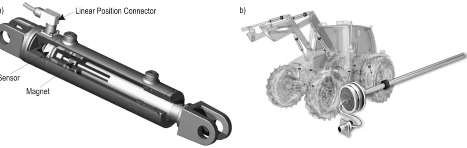
are widely used in robotics are discussed below. 3.4.1 Variable resistance joint sensors
Sensors containing variable resistors or voltage di-viders measure the angle of rotation about a
cylindri-cal joint or its displacement by exploiting the phenom -enon of variable resistance: the voltage across the
resistors in the sensor is proportional to the joint value. These sensors can be placed inside the cylinder, out
-side the cylinder, or at the joints. Examples are shown
in Fig. 1.
When sensors are mounted on the cylinders, both the joint angles and the end effector position have to
be estimated based on the geometry of the machine.
The resolution of the measurement will depend on many factors, the most influential of which are the
voltage range of the sensor and the number of bits in
the Analog to Digital conversion (ADC). For example,
only 1024 (210) different levels can be distinguished with a standard 10 bit ADC. A sensor with such an ADC, a 1 meter opening, and a voltage range of 0 to
5 volts would have a resolution of 4.88 mm according
to the expression below:
2bits Voltagerange
Resolution= × cylinder maximumopening
2bits Voltagerange
Resolution= × cylinder maximumopening (2)
Similarly, when the joint angle is being measured
the resolution in radians can be calculated as:
bits 2
2 Voltagerange
Resolution= × p (3)
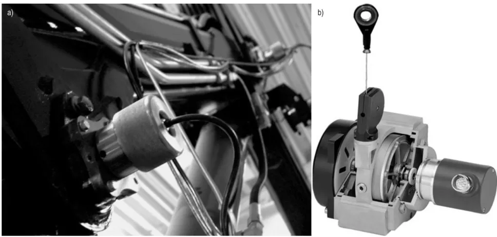
3.4.2 Quadrature optical encoders
Most mechanical manipulators have encoders mounted on their joints to sense their angles of rota
-tion (or displacement in the case of prismatic joints;
see Fig. 2).
The resolution of optical encoders depends on the number of counts they perform per revolution. As -suming a resolution of N counts per revolution, the
accuracy of the measurement is given by:
1 2
Resolution
N p
= × (4)
for rotary motion, and:
1
Resolution maximumdistance
N
= × (5)
for linear motion.
For example, for a resolution of 5000 counts/revo -lution, we obtain an accuracy of 0.0012 radians. The
accuracy in the measurement of the end effector posi -tion can then be estimated using Eq. 1.
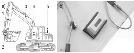
3.4.3 Opto electronic joint sensors
Sensors of this kind are embedded in the joint's hydraulic cylinder (Fig. 3). A reading device is mount
-ed on the head of the cylinder, which reads a pattern (barcode) on the piston rod. The pattern is recognized and the rod position determined by processing soft
-ware. The pattern stamped on the piston rod is highly resistant to the effects of side loading, dust and rust. Such robustness makes this technology attractive for
heavy duty machinery.
The accuracy of such sensors is usually given in
their specifications, and their resolution typically var
-ies from 0.03 mm to 0.25 mm. This is more than suffi
-ciently accurate for most applications. However, it is important to recall that the resolution of the joint an
-gles and end effector poses determined using sensors of this type is also dependent on the geometry of the
machine.
3.4.4 Optical fibre goniometer
The technology used in fibre optic sensors for mea
-suring joint angles was originally developed for the purposes of motion capture. It is therefore used exten
-sively in biomechanics applications and the film in -dustry. In recent years, the technology has matured
and become more robust, leading to applications in more diverse contexts. Its wider uptake has been fa
-cilitated by its simplicity and low setup costs.
Electrogoniometers determine the angle of rotation
about a cantilever joint by using a light sensor housed
Fig. 2 Joint angle sensors with quadrature optical encoders: a) Encoder mounted on a joint; b) Rotary encoder with wire box for measuring linear motion (source: http://www.tfe.umu.se)
in an enclosure to measure the amount of light passing through a pair of optic fibres running along the length
of the cantilever (Fig. 4a). The resolution of the
mea-surement device is typically specified by the product
manufacturer, and usually varies from 0.01 to 0.1 de-grees (0.000174 to 0.0017 radians).
Once again, the resolution for the ultimate
mea-surement of the end effector position can be calculated
using Eq. 1.
3.5 Inertial techniques and tilt sensors
Inertial measurement units (IMUs) are used for
measuring velocity, orientation, and gravitational
forces. Usually an IMU is a box containing sensors of three types; accelerometers, gyroscopes and magne
-tometers. In modern machine applications, IMUs are attached directly to the links in a rugged robust box,
as shown in Fig. 5. To avoid the overhead of installing
external cables, they are often wireless.
These kinds of IMUs are typically based on me
-chanical principles and are equipped with electronics
that generate measurements in the form of electrical
signals. Assuming the measuring device incorporates an ADC, the resolution of its measurements can be
estimated using Eq. 2 and Eq. 3.
A problem often encountered using IMUs is that,
while velocity and acceleration are reliably measured,
it is difficult to obtain reliable positional information. This is because environmental factors (e.g. the pres
-ence of nearby metals, magnetic fields, radio signals, etc.) may cause the output of the magnetometers to fluctuate. Additional software estimation is required to cope with this problem. Observer based estimation techniques, such as Kalman filtering, are used to com -bine the information from the accelerometers and
gy-roscopes of the IMU and obtain statistically optimal estimates of the system's 3D position and angular ori
-entation. Using these data and simple geometrical relationships, it is possible to estimate the pose of the end effector. It is difficult to quantify the resolution of these measurements because it depends on the soft
-ware that is used. Algorithmic estimation can be very
accurate, regardless of the sensor resolution, because
it is under the programmer’s control. This is the main reason why IMU technology has been widely used for
wireless sensing in diverse industries including
mo-tion capture, biomedicine, unmanned aerial vehicles
and robotics.
4. Matching benefits to methods for
estimating the location of the harvester
head
The accuracy required to realize a particular ben
-efit is not by itself sufficient to determine which sens
-ing technologies are best suited to deliver that benefit. More important criteria are the time constraints and the number of positions at which sensors are required. Therefore, we briefly outline the anticipated position
-ing process and then present a match-ing matrix that compares the various benefits achievable with head positioning data to the methods of acquiring such
data.
4.1 The positioning process
Different applications have different positional information requirements. In general, either point or continuous estimates are needed. Point estimates pro
-vide information on the position of the harvester head at specific points in time; they are useful in cases where it is necessary to know the position of a har
-vested tree, for example. Most indirect applications (e.g. those associated with ecological mapping) re
-quire point estimates. Conversely, direct benefits such
Fig. 4 Fibre optic electrogoniometer sensors: a) Joint angle elect-rogoniometer sensor; b) Manipulator with built in electrogoniom-eter sensors (source: http://www.adinstruments.com/)
as those associated with mapping and controlling ma
-chine movements require a continuous flow of infor -mation on the location of the head. In auto-mation
applications this flow must be supplied in real time, which inevitably requires high processing capacity.
Point estimates present less of a challenge but re
-quire precise control over which positions are esti -mated. This can be achieved by connecting the
estima-tion process to specific machine commands. During harvesting, the harvester head grasps the tree when it
is felled. Therefore, if the location and the direction of
a point on the harvester head are known, the position
of the tree's centre can be determined. The estimation
of the head's position (and thus the tree's position) can be synchronized with the action of cutting the tree,
during which the harvester head is held still for a sec-ond or two to enable the chainsaw to cut through the stem. In this case, the harvester head would be in the desired location during the few seconds between
be-ing moved towards the tree and the point at which the
tree starts to fall. Once the tree is felled, the harvester head and tree are moved to enable subsequently cut
logs to fall into separate assortment piles. The position
measurements must, therefore, be acquired quickly
because the head spends relatively little time in the desired position, and there is typically only 30 seconds or so between tree fellings. Moreover, once a given tree's position has been determined, it must be saved
and linked to each of the logs that are subsequently cut from the tree (together with information on the
tree's length, taper, species, and so on). The entire pro
-cess must then be repeated when the next tree is felled.
4.2 Matching matrix
To systemize the matching of benefits and sensing methods, we have constructed a matrix showing how suitable we consider different methods to be for the realization of specific benefits, assuming that the ac
-curacy of the positional data depends only on the ac
-curacy with which the position of the head is estimat
-ed relative to the machine (Table 1). This approach is adopted because we expect that the accuracy of global positioning data for machines will increase substan
-tially in the near future. We also give our opinions on the likelihood that the different methods will be com
-mercialized. For the sake of simplicity, we classify the methods and benefits using a five level scale, and pres -ent both in rather general terms. Nevertheless, the
matrix clearly shows that there are a range of viable
methods that could be used to realize most of the
ben-efits. It also indicates that the methods that are most likely to be implemented commercially, i.e. those based on crane joint position sensors or IMUs, are ca
-pable of meeting the requirements of most benefits
(Table 1).
5. Field experiment 1 – a 2D laser scanner
mounted on a harvester cabin
An alternative to trying to localize the harvester head is to determine the position of the tree that was just harvested. The first step in implementing such a method is to identify a practical way of creating a local map of the trees surrounding the harvester. When a
Table 1 Potential for the implementation of different position sensing methods, and the fit between each method's accuracy and that required to realize specific benefits
Method Implementation potential
Benefit
3D forest
mapping Training of ALS traceabilityTimber featuresProduct tree removalsDensity of
Virtual marking and constraining
Machine (semi) automation
Improving work methods
Angle and/or range 0 + + ++ ++ ++ ++ -- 0
Joint sensors ++ ++ ++ ++ ++ ++ ++ 0 ++
Tilt sensors + ++ ++ ++ ++ ++ ++ 0 ++
IMU ++ ++ ++ ++ ++ ++ ++ 0 ++
Note:
++ – highly likely to be implemented/much higher accuracy than needed; + – likely to be implemented/higher accuracy than needed;
tree is harvested, we should be able to detect which
tree is missing from this map. The reliability of this tree detection process can be improved by accurate
estimations of tree diameter. In this section, we
de-scribe two different field experiments using a SICK LMS 221 2D laser scanner to detect trees. The angular resolution of a single laser beam emitted by the scan
-ner was 0.25° and its field of view is 100°. Each scan consisted of 401 beams. According to the manufac -turer, the laser scanner had a measurement range of
up to 80 m, and a measurement accuracy of ±3.5 cm for ranges up to 20 m. However, to take advantage of
this high accuracy, trees must be distinguished from
other objects (e.g. brush, branches, rocks, etc.). There -fore, a key goal of the study was to evaluate the utility of data collected using a 2D laser mounted on a har-vester.
In the first experiment (Hellström et al. 2012), the laser scanner was mounted on top of a harvester cabin. Measurements were acquired at three different loca -tions in the same forest, with varying degrees of vi-sual obstruction due to branches, leaves, needles, and so on. To identify trees from laser scanning data, the
first thing that must be done is to cluster the laser points. This was done using an algorithm developed by Jutila et al. (2007) with minor modifications. To
validate the clusters, the estimated diameter of each tree cluster has to be calculated and checked to ensure that it is within a reasonable range (between 15 and
80 cm in our study). We implemented and tested the accuracy of several different methods for calculating
tree diameters from clusters in the laser scanning data.
The tree identification algorithm was found to
work reasonably well even at a forest site with quite severe visual obstruction due to branches and needles.
However, a tree that was identified in one laser scan was not always detected in the next even though the
scanner was not moved between scans. It also failed to detect all trees. Some trees were blocked by the har-vester crane and some were blocked by other trees or branches. Several methods for enhancing tree detec-tion were evaluated, such as using median values from several consecutive scans. Overall, however, it was concluded that 2D laser scanners are not suitable or reliable for detecting recently harvested trees due to
uncertainties in tree detection efficiency. However, the detected trees did appear to have been positioned with
at least cm level accuracy (although this was not inves-tigated rigorously).
Another possible use for this tree detection method
is to localize the vehicle relative to the surrounding
trees. By generating a local tree map and matching it with a global map, which could be generated from
ALS data, the machine's position can be determined more exactly than would be possible by using a GNSS (Rossman et.al 2010), which has obvious limitations in dense forests. In this scenario, it is not necessary to find all trees (or a specific one); we need only find enough
trees to allow the accurate matching of local and
glob-al maps.
The results obtained using different methods for
estimating tree diameter varied considerably between
the three experimental sites and also between meth
-ods. The average error for the different methods var -ied between 40% and 90%. No method was best for all circumstances. Since estimated diameters are used to
validate identified tree clusters, a more accurate diam -eter estimation method should increase the number of
trees identified in a given laser scan and thus make it easier to filter out clusters that do not correspond to trees. To develop better methods for diameter estima
-tion, we conducted a second experiment indoors (Ringdahl et al. 2013) using nine tree trunk sections with diameters of 6–50 cm. The tree sections were placed one at a time in an indoor corridor, at distances varying between 5 and 20 meters, with different sides
facing the laser scanner. In total, we measured 172 combinations of stem section diameters and distances. For each measurement, the tree's real diameter was
manually measured with mm accuracy using a caliper at the spot where the laser beams hit. The same cluster -ing algorithm as described above was used to identify trees in the laser scan. However, since there was only one tree in each scan, there was no need for validation of the clustering.
The algorithms for diameter estimation evaluated
in the previous experiment were used again in this study. We also developed enhanced algorithms that compensate for the effect of the beam width and rely on multiple scans. The best existing algorithms overes -timated the tree trunk diameters by ca. 40%. Our en-hanced algorithms reduced this error to less than 12%.
The tested 2D laser scanner thus proved to be un
-suitable for estimating the positions of either harvest
-ed trees or the harvester head. However, its output may be useful in improving the accuracy with which the machine's position is determined, thereby increas -ing the accuracy of other methods for estimat-ing the
head position relative to the machine.
6. Field experiment 2 – encoders
on crane joints
the angular motion of their joints. Below we present
some results from a decade long series of studies
(Or-tiz Morales et al. 2014, Westerberg 2014), whose results contributed to the development and recent release of a commercial product (Cranab 2013b). The aim of this discussion is to illustrate the practicality of this ap
-proach to gathering data on the positions of crane booms. Previous studies (Westerberg 2014) have
shown that the method's accuracy is high enough to
support crane automation; using a similar approach
to that embodied in Eq. 1, it was determined to be of
mm level (Daniel Ortíz et al. 2014).
A Komatsu 830.3 forwarder (Komatsu Forest 2013) was used in the study. The forwarder was equipped with a CRANAB CRF 5.1 crane (Cranab 2013a), which has a reach of 9.3 m. The grapple used was a Komatsu G28, with an Indexator G121 rotator (Indexator 2013).
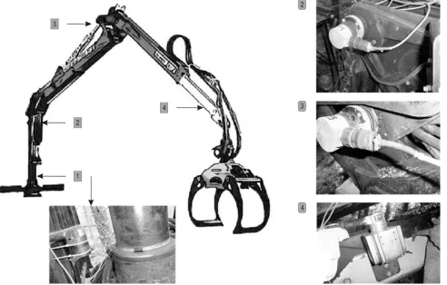
During the experiments, the machine was equipped with four sensors to measure its joint angles and the telescopic displacement (Fig. 6). These sensors were quadrature encoders (Heidenhain, ROD 426−5000)
with a resolution of 5000 pulses per revolution. As such, they provide a measuring accuracy of 0.072 de
-grees (0.0012 rad) for the angular joints and 0.0007 m (0.7 mm) for the telescope. The crane was also fitted
with a real time data acquisition unit that can record incoming signals at a frequency of 1 KHz (1000 record-ings every second).
The sensing system was used to study the working
patterns of experienced forwarder operators. To this end, a group of five professional operators were asked
to use the machine in their normal working routine. Since the only additions to the machine are the
sen-sors, the operators were free to use its standard com
-puter to tune the machine settings to their liking. Po -sitional data were recorded over the course of a week
of scheduled working time for each operator.
The measurements provided by the joint sensors represent angular movement in radians, and displace
-ment in meters in the case of the telescopic link. These
quantities are recorded using the coordinate system sketched in Fig. 7.
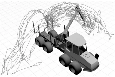
Fig. 6 Forwarder crane with sensors attached at the joint level for measuring angular motion. This experimental platform has been operating
for more than a decade. During this time the sensors have never been changed. Based on this demonstration of the sensing device's
After processing the data, a reconstruction of the boom-tip's motion was generated by considering the
kinematic geometry of the machine (Fig. 8). The results
clearly indicate that it is possible to fit standard forest cranes with joint estimating sensors that can withstand the challenges of forestry operations. Moreover, it also clearly shows the potential benefit of having the capac -ity to analyze and visualize crane work (Fig. 8). In-deed, this kind of visualization is likely to substantially
improve the analysis and evaluation of experienced operators’ working methods, and the training of new operators (Daniel Ortíz et al. 2015).
7. Discussion
Our analysis highlights the joint estimating prin
-ciple and IMUs as the methods with the greatest po
-tential for implementation. Both satisfy the accuracy
requirements for all of the benefits that could poten
-tially be realized using positional data for harvester heads. The practical potential of these technologies is
demonstrated by the fact that two leading forestry
companies have presented solutions incorporating them since the initiation of this project. John Deere
uses sensors in its Intelligent Boom Control solution
to enable boom tip control, and to generate feedback on certain aspects of the working process such as the
frequency at which trees are moved from one side of the machine to another (John Deere 2013). Similarly,
Cranab uses sensors to provide information about the position of the crane boom relative to the machine (Cranab 2013b). As indicated in the analyses, many sensing methods could potentially be used but are less
robust or well suited to heavy duty forest work. The
ongoing development of recently introduced products for positioning the harvester head (i.e. boom tip) will enable the realization of most of the benefits discussed
herein if end users wish to do so. However, the
realiza-tion of some benefits (particularly Timber traceability and improved classification of product properties) will require the development of cost efficient methods for linking information about individual logs from differ -ent stages in the forest value chain.
To accurately determine the harvester head's posi
-tion, we chose to focus on the positioning of the har -vester head relative to the forest machine. However, during the analysis it was noted that the interactions
between certain methods offered opportunities to si
-multaneously estimate local and global positioning. Based on these findings, we believe that combined lo
-cal and global approaches will ultimately be adopted to improve the accuracy of both. However, some of the benefits considered in this work will not gain from high global accuracy. For instance, the benefit that has
the most stringent requirements in terms of relative
accuracy, i.e. machine (semi) automation, is complete
-ly independent of the machine's global position. In contrast, ecological mapping benefits require global
accuracy. However, the required level of local
accu-racy (i.e. accuaccu-racy in determining the head's position relative to the machine) for ecological mapping is
much lower than that for (semi) automation. In the
end, high accuracy in both global and local positioning
will always be useful, as long as it does not come at
too high a price.
Naturally, this kind of study cannot cover all of the
potential benefits that may be realized by accurately measuring the position of the harvester head or a for
-est machine's boom tip; similarly, it would be impos -sible to discuss all of the methods that could be used to acquire such data. Indeed, this overview is already Fig. 7 Forwarder crane coordinate system and generalized joint
coordinates
lengthy enough. However, we hope that by highlight
-ing some of these benefits and promis-ing position-ing
methods, we will introduce a wider audience to the
potential of this recent technical development. In fu -ture, we look forward to building on the results and
ideas presented herein by examining new solutions for realizing some of the prospective benefits arising
from having detailed information on the location of the harvester head.
Acknowledgements
This work was funded by the Royal Swedish Acad
-emy of Agriculture and Forestry (KSLA; H11-0085-MEK, H11-0085-GBN). We would like to thank
Sees-Editing Ltd for revising the English language.
8. References
Alam, M.M., Strandgard, M.N., Brown M.W., Fox, J.C., 2012: Improving the productivity of mechanised harvesting sys -tems using remote sensing. Australian Forestry 75(4): 238– 245.
Andersen, H.E., Clarkin, T., Winterberger, K., Strunk, J., 2009: An accuracy assessment of positions obtained using survey and recreational grade global positioning system receivers across a range of forest conditions within the Tan-ana Valley of interior Alaska. Western Journal of Applied Forestry 24(3): 128–136.
Anon., 2010: StanForD 2010 – modern communication with forest machines. Uppsala, Sweden, Skogforsk. 16 p. Arii, K., Caspersen, J.P., Jones, T.A., Thomas, S.C., 2008: A selection harvesting algorithm for use in spatially explicit individual based forest simulation models. Ecological mod-elling 211(3): 251–266.
Arshadi, M., Backlund, I., Geladi, P., Bergsten, U., 2013: Comparison of fatty and resin acid composition in boreal lodgepole pine and Scots pine for biorefinery applications. Industrial Crops and Products 49: 535–541.
Athanasiadis, I.N., Anastasiadou, D., Koulinas, K., Kiourtsis, F., 2013: Identifying Smart Solutions for Fighting Illegal Log-ging and Timber Trade. In Environmental Software Systems. Fostering Information Sharing, Springer, Berlin Heidelberg 143–153 p.
Barth, A., Holmgren, J., 2013: Stem taper estimates based on airborne laser scanning and cut-to-length harvester meas-urements for pre-harvest planning. International Journal of Forest Engineering 24(3): 161–169.
Berg, S., Bergström, D. Nordfjell, T., 2014: Simulating con -ventional and integrated stump and round wood harvesting systems: a comparison of productivity and costs. Interna -tional Journal of Forest Engineering 25(2): 138–155.
Bollandsås, O.M., Maltamo, M., Gobakken, T., Lien, V., Naes -set, E., 2011: Prediction of Timber Quality Parameters of For -est Stands by Means of Small Footprint Airborne Laser Scan -ner Data. International Journal of Forest Engineering 22(1): 14–23.
Chunhan, L., Yushin, C., Gunhong, P., Jaeheon, R., Seung-Gweon, J., Seokhyun, P., Jae, W.P., Hee, C.L., Keum-Shik, H., Man, H.L., 2004: Indoor positioning system based on inci -dent angles of infrared emitters Industrial Electronics Soci -ety. IECON, 30th Annual Conference of IEEE (Vol. 3).
Cranab 2013a: Cranab - Products - Forwarder Cranes. Avail -able at: http://www.cranab.info/www%5Ccranabcom.nsf/ pages/ProductsForwarderCranes.
Cranab 2013b: Cranab presents an entirely new generation of cranes. Available at: http://www.cranab.se/static/en/206/. Davison, A.J., Kita, N., 2002: Active Visual Localization for Multiple Inspection Robots. Advanced Robotics 16(3): 281– 295.
Dissanayake, M.W.M.G., Newman, P., Clark, S., Durrant-Whyte, H., Csorba, M.A., 2001: Solution to the simultaneous localization and map building (SLAM) problem. IEEE Trans. Robot. Autom. 17(3): 229–241.
Eriksson, D., Lindberg, H., Bergsten, U., 2006: Influence of silvicultural regime on wood structure characteristics and mechanical properties of clear wood in Pinus sylvestris. Silva Fennica 40(4): 743–762.
Eriksson, M., Lindroos, O., 2014: Productivity of harvesters and forwarders in CTL operations in Northern Sweden based on large follow-up datasets. International Journal of Forest Engineering 25(3):179–200.
Fortin, M., Delisle-Boulianne, S., Pothier, D., 2013: Consider -ing spatial correlations between binary response variables in forestry: an example applied to tree harvest modeling. Forest Science 59(3): 253–260.
Gellerstedt, S., 2002: Operation of the single-grip harvester: motor-sensory and cognitive work. International Journal of Forest Engineering 13(2): 35–47.
Hakli, J., Jaakkola, K., Pursula, P., Huusko, M., Nummila, K., 2010: UHF RFID based tracking of logs in the forest industry. IEEE International Conference on RFID. Orlando, FL, USA, 14–16 April, 245–251.
Harter, A., Hopper, A., Steggles, P., Ward, A., Webster, P., 1999: The Anatomy of a Context Aware Application. In Proc. 5th ACM MOBICOM Conf. Seattle, WA.
Heidenhain, 2013: Measurement and Control Technology for Demanding Positioning Tasks. Available at: http://www. heidenhain.de/de_EN/home/.