4
Available online at www.ijiere.com
International Journal of Innovative and Emerging
Research in Engineering
e-ISSN: 2394 – 3343 p-ISSN: 2394 – 5494
Manufacturing of Fixture for Ball Valve Body
Mr. Javed Gulab Mulla
1, Mr. Sanjay Baburao Rathod
2, Mr. Kasim Mahamadrafik Nadaf
3Mr. Pratik Mahesh Deshpande
4and Mr. Onkar Govindrao Deshmukh
51Lecturer, M.E.(Manufacturing process), A. G. Patil Ploytechnic Institute, Solapur, Maharastra, India. 2Lecturer, M.E.(Production Engineering), A. G. Patil Ploytechnic Institute, Solapur, Maharastra, India.
3Student, A. G. Patil Ploytechnic Institute, Solapur, Maharastra, India. 4Student, A. G. Patil Ploytechnic Institute, Solapur, Maharastra, India. 5Student, A. G. Patil Ploytechnic Institute, Solapur, Maharastra, India.
ABSTRACT:
Manufacturing is very important activity in the engineering field, because it is complex to select right process, right machine and right person for creating the new product. In this paper fixture assembly is manufactured for the ball valve body. We got sponsored project for our final year diploma mechanical engineering students from Leena Engineering, Solapur. Actual drafting of fixture is started by refereeing actual component to be machined and finally we created three dimension and two dimension of fixture assembly in AutoCad2010 software. Dimensions of the parts for the assembly are taken on the basis of casting weight and cutting forces that generated during actual machining and by referring other fixtures of similar jobs. Selection of material is done as per standard and that also by referring fixtures of other similar jobs and finally manufacturing of fixture is done by using various machining processes.
Keywords: Fixture manufacture, Location, Work piece , AutoCad
I. INTRODUCTION
A fixture is a work-holding or support device used in the manufacturing industry. Fixtures are used to securely locate and support the work, ensuring that all parts produced using the fixture will maintain conformity and interchangeability. Using a fixture improves the economy of production by allowing smooth operation and quick transition from part to part, reducing the requirement for skilled labor by simplifying how work pieces are mounted, and increasing conformity across a production run. A fixture differs from a jig in that when a fixture is used, the tool must move relative to the work piece, a jig moves the piece while the tool remains stationary. [1]
II. TYPES OF FIXTURE
Though fixtures are predominantly used in milling operation it is used in other operations like turning, boring, welding and grinding. Fixtures are also made for inspection and assembly works. Moreover fixtures are used for castings and forgings which are rough and irregular in shape. With the use of locators and proper clamps, handling of those jobs will be made easy in fixtures than any other standard work holding devices. [2]
A. Adjustable fixture-An adjustable fixture is one which is used in lathe where different cutting tools could be accommodated in one set up, to turn work pieces of different shape and length. The position of the cutting tool is adjusted by different gages.
B. Grinding fixtures-When extreme accuracy is required for grinding parts like connecting rods, valve faces or bevel gears, grinding fixtures are used and they hold parts without any distortion. The positioning of the parts in the fixture is very important and the clamping should be designed to cover the parts for which machining is not required.
C. Welding fixture- Welding fixtures are used to hold the parts in the required shape and are used from smaller parts to larger parts of a plane. Before welding the parts are placed and positioned for the required shape. After clamping the parts welding work will be carried out.
D.Assembly fixture-Large components in airplanes are usually assembled with assembly fixtures. Pipelines and other frames which are so lengthy will be placed in the fixture and assembled. As the use of fixture will be more with lengthy or large components the fixture material has to be stiffer to avoid deflection. Some parts are required to have simple operations like drilling or welding, after aligning with the adjacent parts. An assembly fixture should have to be constructed to accommodate such situations.
5 automotive industries. The fixture will be the master in shape and every part will be compared for its shape conformity. For checking the dimension, the fixture is prepared in such a way that it could accommodate the correct dimensioned parts only.
F. Milling fixture- The use of fixture is oriented mostly with milling operation and there are different types of fixtures available with milling operation.
G.Reciprocating fixture- In a reciprocating milling fixture twin fixtures are mounted on a sliding table with its base fastened to the milling machine. It facilitates the operator to unload or reload one work piece while the other one will be under machining by moving the sliding table in a straight line. The table movement will be achieved either by compressed air or hydraulic fluid.
H.Indexing fixture- When the milling operation is required to fall on a circular path indexing fixtures are used. For milling gears indexing fixtures are used. With multiple indexing head more than one job can be milled at the same time.
I. Straddle milling fixture-Straddle milling fixture is used where milling operation is required simultaneously on either side of a component. This assures the parallelism of the component. Also in taking heavy cuts during the roughing operation two components could be loaded so that this set up will save time.
J. Form milling fixture-For milling ordinary contours like taking a slot or milling a side of a plate form milling fixture is used. More than one component will be fixed in a row and the operation could be done in a single stroke. The work should always be secured in such a way the thrust of the cutter is taken by the solid part of the fixture.
K.Multiple milling fixture- When milling two or more surfaces of a same part which are in relation with each other multiple head fixture are used. This is one type of the special milling fixtures and is used in machining two cylinder faces of a V-engine cylinder block at a same time thereby saving more production time.
Fixtures must always be designed and manufactured with economics in mind, the purpose of these devices is to reduce costs, and so they must be designed in such a way that the cost reduction outweighs the cost of implementing the fixture. It is usually better, from an economic standpoint, for a fixture to result in a small cost reduction for a process in constant use, than for a large cost reduction for a process used only occasionally.
Most fixtures have a solid component, affixed to the floor or to the body of the machine and considered immovable relative to the motion of the machining bit, and one or more movable components known as clamps. These clamps (which may be operated by many different mechanical means) allow work pieces to be easily placed in the machine or removed, and yet stay secure during operation. Many are also adjustable, allowing for work pieces of different sizes to be used for different operations. Fixtures must be designed such that the pressure or motion of the machining operation (usually known as the feed) is directed primarily against the solid component of the fixture. This reduces the likelihood that the fixture will fail, interrupting the operation and potentially causing damage to infrastructure, components, or operators. [3]
Fixtures may also be designed for very general or simple uses. These multi-use fixtures tend to be very simple themselves, often relying on the precision and ingenuity of the operator, as well as surfaces and components already present in the workshop, to provide the same benefits of a specially-designed fixture. Examples include workshop vises, adjustable clamps, and improvised devices such as weights and furniture. Each component of a fixture is designed for one of two purposes: location or support. Following are the basic points, which are required to be considered while manufacturing the fixture[4],
A. Make your manufacturing fixture simple. Simple means less cost to maintain and less opportunity to break. B. Make it easy to use. They should not slow people down.
C. Make it have a purpose. Don’t fixture something just to have a fixture. Make sure there is a problem you are solving. D.Make your manufacturing fixture as cheaply as possible.
E. Make it ‘strong enough’.
F. Make your manufacturing fixture as precise as required. In a manufacturing fixture, precision might be needed for alignment. In another, it may not be. Make sure the precision of your device matches the need. Precision costs money. G.Be creative on where to use it. For example, you can build a manufacturing fixture into a transport cart.
H.Build in reference points in your fixture. Account for variance in the system-uneven floors, varying air pressure in wheels, and variation in carts, for example, might make a part on a cart and an installation fixture hard to match up. If the fixture grabs onto a fixed point on the part, if can make the installation process much easier than trying to match the height independently.
III. DRAFTING OF ACTUAL FIXTURE
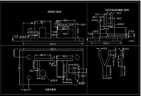
6 drafting are selected. Materials for the same are selected from the referred fixtures. Figures show actual two dimension and three dimension sketches of the fixture and actual component to be machined.
Figure 1. 3D Drawing of fixture.
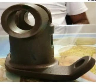
7 Figure 3. Actual component.
IV.MATERIALS AND MACHINING PROCESSES USED FOR THE MANUFACTURING FIXTURE
Jig and fixtures are made from a variety of the materials. There are times where the metals are hardened to resist wear and tear. Sometimes, to prevent damage to work pieces, it is made from nylon/fibre. Material selection in engineering design is very important in all aspects. There are number of engineering design criteria and facts have to be considered when selecting a particular material for a certain component. Though while selecting the materials following are the general things are required to be considered those include high wear resistant, Good corrosion resistant, During loading and unloading of component it should not affect. [5]
For selection of the material for the actual fixture parts, similar fixtures are observed based on which selection of material is done, which are shown in the following table. Following are the different machining processes are used for the manufacture of fixture, these are shown in the table.
Table 1. Materials and Machining processes used for the fixture.
Sr.
No. Name of Part Dimensions in mm Material
Machining processes used
1 Base plate 300*150*13 Hardened Mild steel Grinding and Facing
2 Backing plate 80*20*10 Hardened Mild steel Grinding and Facing
3 Locater pin 13*34.8 Carbon steel Facing and turning 4 Locating cylinder 30*45.4 Carbon steel Facing and turning 5 Backing plate 80*65*10 Mild steel Grinding and Facing
6 Holding rectangular pin 19.6*14.6*19 Cast iron Facing and turning
7 Circular pin 9.5*33.5 Cast iron Facing and turning 8 Backing plate for holding
cylinder 30*65*10 Mild steel Grinding and Facing
8
V. DISCUSSION
In this paper simple steps are taken for manufacturing a such type of fixture. Though more things are considered for the same. This manufacturing of fixture is finally discussed with the sponsored company and after studying all the parameters by them we got final approval and further work is proceeded and finally fixture assembly is manufactured.
VI. CONCLUSIONS
After carrying out this particular type of work, we exactly understood the following things,
1. How to carry out any manufacturing activity means selection of right materials and machining processes for producing a particular part.
2. Processes to be followed for manufacturing a particular component. 3. We got actual work experience of the industry.
ACKNOWLEDGMENT
We would like to express our gratitude to Mr. Sudhir Pulsule , Managing director, Leena Engineering, Solapur, for his consistent guidance and inspiration throughout the project work, which we are sure, will go a long way in our life. We express our sincere thanks to our principal Dr. M. A. Chougule and vice principal Prof. J. M. Jaketia. We express sincere thanks towards Mr. S. K. Mohite, our Head of Mechanical Engineering department, as all the success is the result of his affectionate encouragement. We express our sincere thanks to all our staffs and colleagues who have helped us directly or indirectly in completing this project. Finally, we are grateful for the many useful comments and suggestions provided by reviewers, which have resulted significant improvements.
REFERENCES
[1]Donaldson, Lecain, Goold, “Tool design”, page 573, TATA McGraw-Hill, 2001.
[2]http://www.coe.ou.edu/manufacturing/Fixture%20Design/tutor_files/manual/typesof%20fixtures.htm. [3]https://www.google.co.in/Introduction+of+fixture&oq=Introduction+of+fixture&gs_l.
[4]Dr. P. C. Sharma, “Production Engineering”, page 1, S Chand publication, 2008.