Volume 4, Issue 4, 2017
66 Available online at www.ijiere.com
International Journal of Innovative and Emerging
Research in Engineering
e-ISSN: 2394 – 3343 p-ISSN: 2394 – 5494
Design RF amplifier and LPF for low magnetic field and low
frequency NMR Spectrometer
aAHEJAZ SALAR, bMr. Nimesh Prabhakar
aM.E. - Communication System, L.J Institute of Engineering & Technology (LJIET) Ahmedabad, Gujarat, India. bAssistant professor - Department of Electronics & Communication Engineering L.J Institute of Engineering & Technology
(LJIET) Ahmedabad, Gujarat, India. asalarahejaz@gmail.com , bnimpra28@gmail.com
Abstract-
This paper represents the some important characteristics of Active low pass filter, Operational amplifier and the basic knowledge about NMR system. Nuclear Magnetic Resonance (NMR) is a nuceli (Nuclear) specific spectroscopy that has far reaching applications throughout the physical sciences and industry. NMR uses a large magnet (Magnetic) to probe the intrinsic spin properties of atomic nuclei. Like all spectroscopy’s, NMR uses a component of electromagnetic radiation (radio frequency waves) to promote transitions between nuclear energy levels (Resonance). Most researchers use NMR for structure determination of small molecules. The NMR frequency obtained in the detection experiment carried out finally is expected to be around 6.9 MHz, but reduced the NMR frequency and detect lower frequency of resonance using some techniques. This principle used in Medical technique (MRI) for used to scan human body for find disease. In this paper define the various needed characteristics LPF and RF amplifier require for the NMR spectrometer.
Keywords- NMR , Amplifier ,Radio frequency ,Spectroscopy.
I . INTRODUCTION
Nuclear Magnetic Resonance is a property of the nucleus of an atom, concerned with what is known as nuclear spin (I). This is equivalent to the nucleus acting like a miniature bar magnet. Although isotopes can have a variety of values for I (including zero), the most useful for spectroscopy are those nuclei which have I = 1/2 .Fortunately this includes hydrogen 1 (1H), carbon +13, fluorine 19 , so that some of the commonest elements in organic chemistry can be analyzed using NMR. When a nucleus with I = 1/2 is placed in a magnetic field, it can either align itself with the field (lower energy) or against it (higher energy). If radio waves are applied, nuclei in the lower energy state can absorb the energy and jump to the higher energy state. We can observe either the absorption of energy, or the subsequent release of energy as the nucleus "relaxes" back to the lower energy state. Traditionally this was done by scanning slowly through a range of radio wave frequencies (this is called continuous wave, CW) [9]. It is called the NMR signal. However this has largely been replaced by the faster Fourier Transform (FT) method where one big, broad pulse of radio waves is used to excite all nuclei, then the results are analyzed by computer.
Volume 4, Issue 4, 2017
II. METHODOLOGY
A.Block Diagram
Fig 2. Basic block diagram of system
There are mainly five blocks are available in system: Input system, NMR system setup then after amplifying and filtering device block, output display and DC voltage source block.
B. NMR system
NMR (Nuclear Magnetic Resonance) system consist different parts in it. In NMR system one big coil (Solenoid) is required to produce fix value of magnetic field for getting resonance signal which display onto the output display. So first of all we have to design a solenoid. For getting resonance signal or getting structural information of any substance or sample we have to design one another small sample coil and driving coil which drive the proton of the sample.
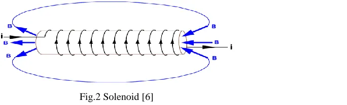
1. Solenoid :
A solenoid is a coil wound into a tightly packed helix. In physics, the term refers to a coil whose length is substantially greater than its diameter, often wrapped around a metallic core, which produces a uniform magnetic field in a volume of space when an electric current is passed through it. A solenoid is a type of electromagnet when the purpose is to generate a controlled magnetic field. [7]
Fig.2 Solenoid [6]
As our requirement we have to decide the values of required turn (N) around the metallic core, length of the metallic core (L) and Current pass through it and using equation (2) we can calculate the fixed magnetic field value of the solenoid. DC voltage via DC generator to pass through the solenoid and produce fix magnetic field into solenoid and we can change the value of magnetic field via controlling the value of current pass through it.
B=
I
L
N
0
Volume 4, Issue 4, 2017
68 2. Sample coil :
It is a main part of system to design and place sample or a substance into the core of the sample coil and the another drive coil place outside the surface of core and it is perpendicular to the sample coil. The sample coil placed into the core of solenoid and it is perpendicular to the core of the solenoid because of this type of setup we can get the resonance signal of the sample. Sample coil and driving coil provide AC signal via function generator and give it output to the amplifying device like RF amplifier.
Fig.3 Sample coil and sample [8]
C. Resonant receiver
There are many high frequency signals are available in environment like TV signal, Cell phone signal, RF signals etc. So that our sample coil is simply work as a antenna so that it can pick up all types of signals from environment so that noise increase in output so that we have to required one tuned capacitor parallel to the sample coil so that it is only tuned sample circuit around the resonance frequency so that it is reduced the noise from output and we get better results at output.
Fig.4 Tuned capacitor
The value of tuned capacitor we can find by this equation. The value of L is the inductance of the sample coil in which any sample placed and observe the resonance frequency and signal of the sample’s proton and calculate magneto gyric ratio of the signal.
LC
1
D. Diode detector
Volume 4, Issue 4, 2017
Fig.5 Iput signal Fig.6 Output signal
E. Filter
A low-pass filter is a filter that passes signals with a frequency lower than a certain cut off frequency and attenuates signals with frequencies higher than the cutoff frequency. The exact frequency response of the filter depends on the filter design. The filter is sometimes called a high-cut filter, or treble cut filter in audio applications. A low-pass filter is the complement of a high-low-pass filter.
The output of RF amplifier is noisy so that we can’t get resonance signal properly onto the output display so that at low frequency we require to design the low pass filter and pass the output of RF amplifier to the low pass filter so that we get resonance signal properly and accurately with very low noise compare to RF amplifier output signal at output display.
There are two types of low pass filter available:
Active low pass filter Passive low pass filter
Passive filters are made up of passive components such as resistors, capacitors and inductors and have no amplifying elements (transistors, op-amps, etc) so have no signal gain, therefore their output level is always less than the input.
In Active low pass filter is completely different from passive low pass filter because in active filter use active component op-amp to increase the gain of the signal so that this is the main advantage of the active low pass filter. With passive filter circuits containing multiple stages, this loss in signal amplitude called “Attenuation” can become quiet severe. One way of restoring or controlling this loss of signal is by using amplification through the use of Active Filters.
So that we have very low voltage signal at the output of the RF amplifier so that we use active low pass filter with amplification of the signal.
Here the cut off frequency value is around 200 Hz and the gain of the op-amp is set 10 and then after give the output of the LPF to the RF amplifier which is amplify the signal to high gain.
Volume 4, Issue 4, 2017
70 In fig. 7 shows that the gain of the op-amp we can adjust via change the suitable value input resistance and feedback resistance value. And the value of capacitor define by cut off frequency of the low pass filter using below equation.
Gain of first order low pass filter is:
Voltage Gain ,(Av) =
in out
V
V
=
2
1
c F
f
f
A
Where:
AF = the pass band gain of the filter, (- RF/R1) ƒ = the frequency of the input signal in Hertz, (Hz) ƒc = the cut-off frequency in Hertz, (Hz)
F. RF Amplifier
A radio frequency amplifier (RF power amplifier) is a type of electronic amplifier that converts a low radio-frequency signal into a higher signal. There are different types of RF Amplifier are available: voltage amplifier, power amplifier, operational amplifier etc. We used operational amplifier as a RF amplifier for our system because at very low frequency and low magnetic field operational amplifier is suitable to our system. There are two types of op-amp are available.
Inverting operational amplifier Non-inverting operational amplifier
Here we used inverting operational amplifier for requirement of the system. Here we used inverting operational amplifier for requirement of the system with set gain 100.
Fig .8 Closed loop non inverting op-amp
As per the requirement of the system we have to decide the value of the gain of operational amplifier. So that we have to fix the value of R1 and RF .The gain of the closed loop non-inverting op-amp is defined by equation which shows under. The output and input are at 180 phase difference in inverting op-amp.
Av =
in out
V
V
= -
1
R
R
FVolume 4, Issue 4, 2017 III.SIMULATION RESULTS
G. Active LPF
The simulation result of low pass filter shown below figure. From shown figure we can conclude that at low frequency (204 Hz) we get the maximum gain of the op-amp and as frequency increase the gain of thw op-amp will decrease so that as our requirement of low frequency we get the proper results from ALPF and it is neglect the high frequency signal and attenuate the high frequency signal.
Fig.9 Filter chart
H. RF amplifier
Fig.10 RF amplifier chart Freq (Hz) Gain (dB)
50 19
100 19
150 19
204 17
250 16
300 15
Freq (Hz) Gain (dB)
100 40
200 40
300 40
500 40
1k 40
2k 39.8
Volume 4, Issue 4, 2017
72 From simulation results of RF amplifier we can conclude that the gain of the RF amplifier we set at 40 dB manually then from the results we can conclude that we achieve this value at required low frequency around 200 Hz so that it is proved.
III.ANALYSIS OF RESEARCH PAPERS
Xiaoying Tang, Xinfen Hu, Zhiling Dai, Tianxiang Zhang, Weifeng Liu had been developed that the main role of the RF power amplifier is carrying out the power amplification of the radio-frequency signal , In fact, the power is impossible to be enlarged; the power amplification here refers to the power’s conversion under some control signal. That’s to say, under the control of radio-frequency signal, the power Pd provided by the direct-current power supply is transferred to power Po and put out. During this process, collector dissipation P C exists in the transistor itself. The relationship among the three can be expressed as follow:
Pd Pc Po
The key to increasing the output and raising the efficiency is cutting the dissipated power, so how to reduce the dissipated power is an essential requirement of the high frequency power amplifier. [2]
J.T.Vaughan ,D.N.Haupt, P.J.Noa and G.M.Pohost had been developed that the three-fold increase in signal-to-noise over the present 1.5T commercial systems, and other proven advantages of NMR imaging and spectroscopy at field strengths of 4.1 Tesla, point toward the need to develop optimized high field clinical systems for medical science and diagnostics. Other than the large bore, high field magnet itself, the key technological differences between commercial 1.5 T clinical systems or higher field "animal bore" systems, and a 4 Tesla system for human studies, are found in the radiofrequency (RF) front end of the system spectrometer. When compared to lower field clinical systems, higher RF transmit power levels are required for human studies at 4T to cover broader spectral bandwidths, correct for chemical shift dispersion error and to a lesser extent compensate for RF losses. For human studies, more RF power is needed for stimulating an NMR response from larger and deeper regions of interest than in smaller animal subjects at similar or higher frequencies. These higher RF power levels require new front end circuit technology. [5]
Aktham Asfour had been designed and development of a new home-built NMR spectrometer working at very-low magnetic field (4.5 mT). This spectrometer allows detection and acquisition of NMR proton (H) signals. It consists of a resistive magnetic (Helmholtz coils) that produces the static magnetic field of 4.5 mT. The transmitter and the receiver were built by using available DAQ boards form National Instruments. These boards are controlled using Labview environment. The system is versatile, flexible and easy to replicate. This was actually the underlying idea behind this
development. [4]
M. Tsuchiya, T. Wakuda, K. Maki, T. Shiino, H. Tanaka, N. Saho, H. Tsukamoto, S. Kido, K. Takeuchi, M. Okada, and H. Kitaguchi developed a high-resolution NMR spectrometer with a superconducting split magnet and a cross-shaped bore. Because of the spatial limitations of the magnet’s structural design, the split magnet requires many pairs of coils to generate a high magnetic field. For this reason, it is difficult to compare the high stability and homogeneity of its magnetic field to conventional NMR magnets.
Therefore, they have developed advanced superconducting magnet technologies and successfully fabricated two types of self-shielded superconducting split-magnet systems: a 7 T (300 MHz) and a 14 T (600 MHz) magnet system. The 300 MHz system consists of 12 NbTi coils with 15 joints and a stored energy of 0.7 MJ; it achieved a field drift of about 0.1 Hz/h in persistent current mode operation. The 600 MHz magnet system consists of 12 Nb3Sn coils and 8 NbTi coils with 53 joints and a stored energy of 10 MJ. Its field drift was less than 1 Hz/h. [3]
Volume 4, Issue 4, 2017 as the field stability, will be evaluated. In the final step of the project, the replacement of the innermost coil of the existing 920 MHz NMR magnet will be planned. The targeting field is 24.7 T (1.05 GHz for _H NMR resonance frequency). [1]
IV. CONCLUSION
This paper represents basic principle of RF amplifier and filter briefly and according to the requirement of the NMR system. Using proper set up of the NMR system, RF amplifier, Filter and all remaining components of NMR system we will get resonance signal at the output display of the system. And from simulation results we can conclude that the RF amplifier and Active low pass filter are work properly at desired frequency of requirement.
V. REFERENCES
[1] T. Kiyoshi, A. Otsuka, S. Choi, S. Matsumoto, K. Zaitsu, T. Hase, M. Hamada, M. Hosono, M. Takahashi,T. Yamazaki, and H. Maeda, “NMR Upgrading Project Towards 1.05 GHz” , IEEE Transactions on applied superconductivity, VOL. 18, NO.2,JUNE 2008.
[2] Xiaoying Tang, Xinfen Hu, Zhiling Dai, Tianxiang Zhang, Weifeng Liu, “RF Power Amplifier of NMR System” , I EEE Conference publication, 2009
[3] M. Tsuchiya, T. Wakuda, K. Maki, T. Shiino, H. Tanaka, N. Saho, H. Tsukamoto, S. Kido, K. Takeuchi, M. Okada, and H. Kitaguchi, “Development of Superconducting Split Magnets for NMR Spectrometer” , IEEE Transactions on applied superconductivity, VOL. 18, NO. 2, JUNE 2008
[4] Aktham ASFOUR, “A new DAQ-based and versatile low-cost NMR spectrometer working at very-low magnetic field (4.5 mT): a palette of potential applications”, 2008 IEEE - International Instrumentation and Measurement Technology Conference.
[5] J.T. Vaughan, D.N. Haupt, P.J. Noa, and G.M. Pohost, “RF Front End for a 4.1 Tesla Clinical NMR Spectrometer”, IEEE Conference publication, 1994.
Websites :
[6] https://www.google.co.in/search?q=sample+coil+like+solenoid&espv=2&biw=1600&bih=794&source=lnms&tbm =isch&sa=X&ved=0ahUKEwin0oPj0LLSAhUGhrwKHedAGIQ_AUIBigB#tbm=isch&q=+solenoid&*&imgrc=cty qKr00od3FHM > (solenoid)
[7] https://en.wikipedia.org/wiki/Solenoid > (solenoid)
[8] https://www.google.co.in/search?q=sample+coil+like+solenoid&espv=2&biw=1600&bih=794&source=lnms&tbm =isch&sa=X&ved=0ahUKEwin0oPj0LLSAhUGhrwKHed-AGIQ_AUIBigB#imgrc=pzzoMTBvFM9qrM:> (sample coil)