Volume 3, Issue 4, 2016
31 Available online at www.ijiere.com
International Journal of Innovative and Emerging
Research in Engineering
e-ISSN: 2394 - 3343 p-ISSN: 2394 - 5494
A COMPARATIVE ASSESSMENT BETWEEN
CONVENTIONAL METHOD AND MODIFIED METHOD
OF MINIMUM BATTERY SIZING FOR COST EFFECTIVE
SOLAR PV SYSTEM
Rakhi Sharma
a, G.N. Tiwari
b, R.Uma
baSchool of Engineering & Technology,Indira Gandhi National Open University,
Maidan Garhi, New Delhi,India,Pin-110068
bCentre for Energy Studies (CES), Indian Institute of Technology (IIT) Delhi, Haus Khas, New Delhi, India, Pin-110016
ABSTRACT:
In developing countries, there is a need of small scale low cost Photovoltaic (PV) power systems that provides stand-alone PV system with minimum battery or without battery to obtain minimum cost and less maintenance of batteries. Present paper expresses need of minimum battery sizing under certain suitable operating conditions and applications. Conventional methods which are being adopted for determining required battery bank capacity consider total Ah/day or Wh/day used by connected loads during day and night both, that means battery bank is sized to serve day (which is served by PV array) and night load both and again battery bank is oversized by considering battery autonomy days. This paper presents a comparative assessment of estimating minimum battery sizing for given rated power of stand-alone PV (SAPV) system for different mode of operations using conventional battery sizing method and proposed modified method of minimum battery sizing based on night load demand.
Keywords: photovoltaic, solar, battery sizing, ampere hour, cost effective
Nomenclature
AC Alternative current
Ah Ampere hour
(Ah)BB Calculated required battery bank capacity (Ah)
Ah
night load_ Connected night load Ampere hours (Ah)
Ah
day_load Connected day load Ampere hours (Ah)(Ah) b Battery capacity of commercially available battery selected for PV installation (Ah) (Ah)inst Battery bank capacity for PV installation (Ah)
BB Battery Bank
d Day
DC Direct current
(DoD) max. Maximum depth of discharge
hEFS Equivalent hours of full sunshine (hours) inst Installation
kWp
Kilo Watt Peak or peak power at STC
n Battery autonomy in terms of multiplying factor for connected night load Ah N Battery autonomy in terms of multiplying factor for connected day and night
load Ah
Nb Number of series batteries in a string Nb Number of series batteries in a string
Ns Number of strings of series batteries in the PV battery bank installation
PV Photovoltaic
Volume 3, Issue 4, 2016
32 VBB Operating voltage for required battery bank (V)
Vb Voltage rating of commercially available battery selected for installation (V) Vinst Operating voltage of battery bank in PV installation (V)
PV
Overall PV efficiency coefficient (dimensionless)c Charge controller efficiency coefficient (dimensionless)
in
Inverter efficiency coefficient (dimensionless)w
Wiring and cabling efficiency coefficient (dimensionless)b
Battery efficiency coefficient (dimensionless)I. INTRODUCTION
Electrical energy generation from solar energy by photovoltaic (PV) has been considered most practical and environment friendly way. About 60% of the world’s manufactured solar cells are used for stand-alone photovoltaic (SAPV) systems. In developing countries where there are availability of grid electricity still very less or even no electrification of any kind in the large rural areas, deployment of new stand-alone photovoltaic (SAPV) systems can play major role in electrification. The battery storage is one of the key components within photovoltaic stand-alone systems. Compressed air flywheels, super capacitors, super conducting magnets, electrochemical storage and hydrogen are few storage devices [1]. Among various options, electrochemical storage in the form of battery is suitable for PV energy storage and most commonly used one.
Importance of battery in PV system is due to the fluctuating nature of the output delivered by the PV arrays. During the hours of sunshine PV system directly feeds the electrical energy to the load, and the excess amount of electrical energy is stored in the battery. This stored electrical energy is supplied to the connected load from the battery during the night hours, or during a period of low solar intensity.
Most often used classic lead-acid (PbA) batteries are produced especially for solar photovoltaic (PV) systems, where deep discharge is required. Alkaline batteries are also suitable for PV applications, however at present nickel-cadmium has acceptable performance characteristics and lifecycle costs for these applications. However, in practice other battery types, such as nickel-cadmium (NiCd) or nickel metal hydride (NiMH), are rarely used, except in portable devices. Typical solar system batteries lifetimes span from three to five years, depending heavily on charging/discharging cycles, temperature and other parameters. The Ni–MH battery system is based on the Ni–Cd battery, which substitutes the toxic Cd-electrode by the MH electrode [2]. However up to now lead–acid batteries has been the most cost-efficient technology for photovoltaic stand-alone systems. Minimization of necessary storage for far-off applications results in a reduction of battery sizes, thus makes stand-alone photovoltaic systems (SAPV) more cost-effective and energy efficient [3]. Conventionally, a lead-acid automotive battery has been used in most PV installations.
Numerous optimal sizing methodologies have been developed by several scientists that include analytical solutions and numerical method approaches for stand-alone systems. This conclusion was made that that numerical models are accurate but difficult to use, while analytic models display significant lack of accurateness [4,5]. PV sizing methods discussed by Posadillo and Luque(2008)[6], Sidrach-de-Cardona and Mora Lo´ pez (1998)[7] , Barra et al.(1984)[8], Bartoli et al.(1984)[9] and Bucciarelli(1984)[10] were reviewed and the basis for the present minimum battery sizing method for a given rated photovoltaic system has been proposed. Out of total energy requirements, energy requirements that production and transport of batteries contribute are 24–70%, and the PV array contributes 26–68% to energy requirements. The contribution from other system components is less than 10%. For a PV-battery system with a service life of 30 years, this corresponds to energy pay back times between 2.5 and 13 years. The energy payback time is 1.8–3.3 years for the PV array and 0.72–10 years for the battery [11].
In PV system annual costs of the storage reflect the real storage costs (initial cost) and take the storage lifetime or replacement cost and maintenance cost into account. If the battery lifetime is below 3.5 years the battery is the most expensive component in the system. The costs of the battery are even more unfavorable, if the maintenance costs, which are generally caused by the battery, are added. Low maintenance or maintenance free operation is an important parameter, especially if the systems are located in a rural area and the system size is small. The annual costs of the storage are almost in the same range as the annual costs of the solar generator.
Volume 3, Issue 4, 2016
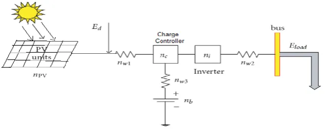
33 batteries and finally, one or more inverters connected in parallel, for converting DC into AC. In addition to the individual units, the corresponding efficiency coefficients PV,w,i, c are also depicted. Ed is energy delivered by PV array and Eload presents energy received at load terminal.
Figure 1: Schematic diagram of stand-alone PV System with individual unit efficiency coefficient.
The battery size is dependent upon the load energy requirement and on site weather patterns. Over the years a number of battery models have been developed. Most of these models can be defined as phenomenological, namely they are based on observable quantities such as voltage, current and time, and do not depend on the internal structure of the system.
Present chapter suggests suitable conditions for considering optimal battery sizing methodology on the basis of night load demand and equivalent hours of full sunshine (peak sunshine hours) during clear day conditions for a chosen reliability. A PV battery system with perfect reliability is oversized to meet a relatively short interval of time when it is faced with some critical operating conditions such as cloudy weather. In the present work an attempt has been made to estimate minimum battery bank size for a given rated stand alone PV (SAPV) system for different mode of operations and a significant reduction in battery bank capacity is observed with reduced night load demand. To obtain comparative assessment variation in required minimum battery bank capacity for different day and night load Ah distribution has been presented with different equivalent hours of full sunshine(hEFS) by using both conventional and presented modified method of minimum battery sizing.
II. PROBLEM ASSOCIATED WITH ELECTROCHEMICAL STORAGE BATTERY IN PV SYSTEM
In most developing countries, a major failure mechanism of small stand-alone PV system has been due to inadequate attendance and maintenance of PV storage batteries. There is requirement of periodic addition of distilled water in most of the electrochemical batteries. Demand of the periodic addition of distilled water in electrochemical storage batteries may be a trivial matter when distilled water may just not be available at site that may be far removed from nearest township or has been ignored due to carelessness or less understanding. In such cases it is necessary to plan ahead of time for regular supply of distilled water.
Another important part of the inspection sequence is routine and periodic checking of specific gravity of electrochemical cells. For this, it must be ensured that an appropriate hydrometer is available at the site for carrying out such a regular function. In addition, over a period of time the terminal of storage battery will have accumulation of solid white deposits. Such deposits must be cleaned regularly as this may cause high resistance to current flow or even an open circuit. Preventive mechanism as application of petroleum jelly on terminal port should be used to avoid this.
Battery bank is always electrically live so handling and installation of the battery banks are especially critical. Further, it must be ensured that proper ventilation is provided for the escape of generated hydrogen gas that would be generated when battery bank were being charged. Failure to this may cause electrical spark or even an explosion and the possibility of acid spillage from the storage batteries. Installation at remote and far village sites tend to ignore the extreme importance of safety precautions at all the stages. It must be remembered that accidents are caused by a lack of care and understanding.
In lot of applications where only reliability of PV system which is obtained in terms of using oversized battery in order to get continuous electricity in day and night time throughout the year is not so necessary, then this becomes important to evaluate optimal size of battery in order to get reduction in installation cost and regular maintenance of PV system.
Volume 3, Issue 4, 2016
34 Consequently, during peak sunshine days, the battery will remain near a fully charged state with the array generating excess energy. In order to prevent the battery from overcharging, it needs to be either disconnected or dissipated. These clear sky insolation periods of the year require minimum storage capacity in PV system.
The optimized storage battery in general should have the minimum size which meets the demand requirements during the application period [12].This section presents importance of battery sizing based on night load demand. Drawback of present conventional methods of battery sizing is the use of oversized battery in all kind of applications that cause uneconomical storage system and require more maintenance PV system.
Conventional methods which are being adopted for determining required battery bank capacity consider total Ah/day or Wh/day used by connected loads during day and night both, that means battery bank is sized to serve day and night load both. But in actual during installation initially we get full charged battery and almost all day load is served by PV array power (during clear day condition).This means battery is almost not get discharged or slightly used during day time and this mostly get discharged during night time only as per night load requirement. Throughout the year in conventional method battery autonomy is considered for 24 hours as per both day and night Ah requirement of load. This clearly indicates that oversized battery is generally used for normal clear day operations and which is not economical. Again consideration of autonomy days or battery autonomy cause more over sizing of battery capacity and in turn cause more cost.
Present conventional methodology of battery sizing cannot be ideal or optimum for all the cases. For example if any particular place which does not require consideration of days of autonomy due to its rare occurrence throughout the year, then consideration of day and night load (Ah/day) in sizing calculation cause over sizing of battery and increase overall system cost that is initial capital cost and then running cost due to maintenance. In such cases, this method of sizing will also be more inaccurate when in a particular application of SAPV system, day load requirement is high (more than 50%) then night load requirements.
Consideration of minimum battery sizing method on the basis of night load demand for estimating battery size in terms of overall cost and maintenance reduction is useful under following given conditions:
Requirement of small low cost PV technology that provides complete stand-alone PV system and connected loads are being used to serve residential and agricultural applications of remote and rural areas where getting electricity and transportation facilities are difficult and maintenance of battery is difficult on regular basis.
PV system is potentially used during clear days (in general during summer and winter) and battery is charged and discharged every day. Consideration of battery autonomy days is not so important for particular application.
There is not complete utilization of PV array power and PV battery power. For example, PV array produces sufficient power but PV system is not used for serving entire day and night load and only partial loads are connected during day and night time.
In applications where high reliability of PV system is not required during partial clear day or in cloudy conditions, any other auxiliary power source can also be used for some short period during any non-reliable PV operating conditions. However, maximum reliability of PV system is achieved during clear day condition.
PV load applications such as battery charging ,agriculture pumping operation etc., where application of these loads are important, but working time and amount of work done at any particular time during day or night hours can be compromised.
Any other power supply source is already available at site with less costly PV system, for example hybrid systems with increasing role of the diesel gen-set and relatively smaller PV-generators and batteries.
To optimize renewable energy systems many attempts have been made. Among them, most studies highlighted on hybrid wind/solar array systems with a battery[13,14,15,16,17]. In these hybrid PV systems, solar energy and other energy source are combined together to feed a load as a more reliable system [18, 19], thus, the size of the battery is relatively small and the role of the battery in hybrid system is less than that of in the stand alone PV system.
IV.TECHNICAL TERMS IN BATTERY SIZING Some fundamental technical terms used in the battery sizing are briefly reviewed:
Equivalent hours of full sunshine (hEFS) or peak sunshine hours (PSH)-Equivalent hours of full sunshine is defined by
number of hours of incident radiation at a place, if intensity of radiation is kept constant at its max. value of 1kW/m2 that gives the same energy received from sunrise to sundown[20].
Volume 3, Issue 4, 2016
35 Some general important notions for battery- Some fundamental concepts of the battery such as nominal rated capacity, state of charge (SOC), discharge rate, self discharge, deep cycle and shallow cycle, lifetime, maximum depth of discharge (DODmax) are briefly reviewed:
Nominal rated capacity- Maximum number of ampere-hours (Ah) or maximum amount of energy that can be extracted from the battery, under defined operating conditions, without adversely affecting performance is its nominal rated capacity. State of charge (SOC) - SOC is represented by the ratio between the present capacity and the nominal capacity (0≤ SOC≤1).
SOC=1 represents, battery is totally charged, otherwise SOC=0 represents that battery is totally discharged.
Discharge rate- Discharge rateis the important operating condition that is specified by the manufacturer, for example nominally rated capacity of battery C(N)= 100Ah at C(N)/10 rate. Here, 10 hours discharge rate, means that the rated capacity is available from the battery if constant current of value equal to C(N)/10, here 100/10=10A is drawn from the battery. Generally, most PV systems are so designed that the actual rate of discharge of the battery hardly ever approaches the specified maximum value of, say C (N)/10.
Efficiency– Normally the relation between a normal discharge and the necessary recharge is the basis on which efficiency is considered. This is the ratio of the charge extracted (Ah or energy) during discharge to amount of charge (Ah or energy) needed to restore the initial state of charge. It depends on the state of charge SOCand on the charging and discharging current.
Self discharge-There is some loss of useful capacity of a storage battery that occurs due to internal chemical action, whether the battery is loaded or not. Depending on the used technology self-discharge may vary from less than 2% to more than 40% per month.
Deep cycle and shallow cycle-Deep cycle type of battery can be discharged to a large function of its capacity .Deep cycle lead acid battery can endure discharge up to about 80%.Shallow type battery should not be discharged greater than approx. 20% or 25%. For most PV applications deep cycle batteries are preferred.
Lifetime-Lifetime is the number of cycle’s charge/discharge the battery can sustain before losing 20% of its nominal capacity.
Maximum depth of discharge (DODmax) - Percentage of the nominal rated battery capacity that can be safely drawn from
it without badly affecting its performance. The available battery capacity and cycle life depend on its acceptable maximum depth of discharge.
V. BATTERY SIZING METHODOLOGY FOR GIVEN RATED POWER OF STAND-ALONE PV SYSTEM
This section presents battery sizing methodology for a given rated PV array size (in kWp). To obtain battery capacity for a given rated PV array initially the estimation for connected electrical load that can be served by PV array has been carried out.
Estimation of connected optimal electrical load
The existing system makes use of a PV array of size in kWP. Energy delivered by PV array(Ed) in kWh/d can be obtained by multiplying PV array size (in kWp) with equivalent hours of full sunshine (hEFS) or peak sunshine hours (PSH) and this is expressed by Eq.(3).
EFS
d p
E
kW
h
(3)From this value, the corresponding connected electrical load that can be operated from this PV array system will be equal to the total energy available at the load terminal. It can be expressed in form of Eq.(4)
Estimated electrical energy available at load terminal (Et) =Estimated electrical load (El) connected to PV system. (4)
Here estimated electrical load connected to PV system can be calculated approximately by taking various efficiency coefficients into account as shown in Eq.(5).
Estimated electrical load connected to PV system (in kWh/d) = Energy delivered by PV array (in kWh/d) x Overall efficiency coefficient
l d pv
E
E
(5)pv ar c in w
(6)Volume 3, Issue 4, 2016
36 The solar modules are used for direct supply as well as for re-charging the batteries. Direct operation during times of sunshine allows the battery set to be small and thus cost-efficient because generally it will only have to bridge the hours of the night.
The parallel operation of a solar power system and batteries will ensure that even during power failure, electricity will be available for a significant period.
Connected electrical load in ampere hour per day (Ah/d)l is estimated from Eq.(7)
/
l ldc
E
Ah d
V
(7)El is estimated connected electrical load (in kWh/d) and Vdc is selected operating DC voltage (V).To include the effect of losses in battery due to its efficiency, above estimated connected electrical load (in Ah/d) is converted into the corrected load Ah/d for battery design(Ah/d)c by using Eq.(8)
(
/ )
(
/ )
lc
b
Ah d
Ah d
(8)Total corrected load Ah/d that is used for battery designing includes total Ah required for both day load and night load. In conventional battery sizing method the parameter total connected load Ah/d includes the value of total day and night load Ah,whereas, in actual condition battery is meant to serve mainly night load Ah only as day load Ah is served by PV array power. It can be said that for all clear days or for most of the time during a year we are using oversized battery by considering the day Ah for all the time in present conventional method of battery sizing.
In conventional method required battery bank capacity in Ah is estimated on the basis of day and night connected load Ah during 24 hours as given by Eq.(9)
_
_max
[
night load day load]
BB
Ah
Ah
N
Ah
DoD
(9)where, N represents battery autonomy, indicates multiplying factor of connected day and night load (Ah) during 24 hours and represents number of times of total load Ah(day and night) that battery can serve without day time charging.
Here we are presenting modified battery sizing method based on night load requirement to estimate optimal battery size. To show the variation in required battery bank capacity with different day and night load distribution , for simplification we have considered different combination of day and night percentage (%) of load Ah (i.e. 0% night,100% day; 25% night,75% day ; 50%night ,50% day; 75% night,25%day; 100%night,0%day) while battery sizing calculations. Calculated required battery bank capacity in Ah on the basis of night load requirement in 12 hours as per proposed modified method is given by Eq.(10)
_
max night load BBAh
n
Ah
DoD
(10)where, (Ah)BB is calculated required battery bank capacity in Ah,
_ night loadAh
represents night load Ah which is the partof total Ah that is used by connected night load.
n represents battery autonomy. Here n is indicated as multiplying factor of connected night load (Ah) during 12 hours and represents number of times of night load Ah that battery can serve without day time charging. To obtain minimum battery size n=1 is considered. (DoD)max is maximum depth of discharge of battery.
Further, based on estimated required battery bank capacity in Ah, number and rating of commercially available batteries are selected for the installation of PV battery bank.
In installation of PV battery bank number of series batteries in a one string can be represented by Eq.(11)
BB b b
V
N
V
(11)where, Nb is number of series batteries in a string, VBB is operating voltage for required battery bank, Vb is voltage rating of commercially available battery selected for installation.
Now required number of strings of series batteries in the PV battery bank installation can be given by Eq.(12)
BBs
b
Ah
N
Ah
Volume 3, Issue 4, 2016
37 where, Ns is number of strings of series batteries in the PV battery bank installation, (Ah)BB is calculated required battery bank capacity in Ah, (Ah)b is a battery capacity (in Ah) for commercially available battery selected for installation. Now following Eq.(13) and Eq.(14) represent installed battery bank capacity in terms of ampere hour (Ah) and voltage(V) respectively.
Ah
inst
Ah
b
N
s (13)inst b b
V
V
N
(14)where, (Ah)inst is battery bank capacity in Ah for installation, Vinst is installation voltage for battery bank and this will be equal to operating DC voltage.
VI. ESTIMATION OF OPTIMAL PV BATTERY SIZE FOR DIFFERENT MODE OF OPERATIONS
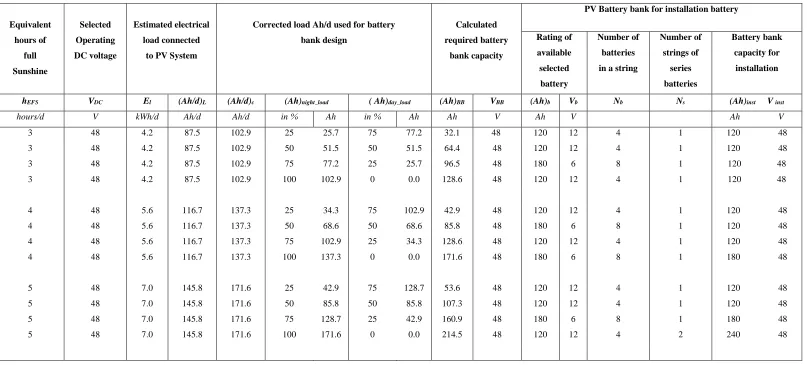
Table 1 shows minimum battery sizing estimation for 2kWp stand-alone PV system for different mode of operations using modified method. Battery bank capacity is calculated for different combination of day and night percentage (%) of load Ah (i.e. 0% night,100% day; 25% night,75% day ; 50% night ,50% day;75% night,25% day;100% night,0% day) for different value of equivalent hours of full sunshine or peak sun hours as per PV installation location. Battery autonomy is considered as n=1in this minimum battery sizing estimation. In modified battery sizing method n indicates as multiplying factor of connected night load (Ah) or battery autonomy and represents number of times of night load Ah that battery can serve without day time charging. if n=2 then battery can serve amount of Ah to connected load equal to the 2 times of considered night load Ah without any charging during day time.
It is clear that consideration of more battery autonomy during sizing , no doubt will increase the reliability of PV system operation but in the same time this will cause over sizing problem which in turn increase the cost and maintenance in PV system. In applications and in places where SAPV system is mostly used during clear day conditions and consideration of autonomy days are not so important then suggested methodology provides minimum battery size with minimum cost.
If certain limitations i.e. suitable conditions for minimum battery sizing are not followed in this presented modified battery sizing method based on night load requirement then while evaluating battery capacity one has to compromise with reliability issues in terms of battery autonomy, which occurs during some critical conditions of off sunshine only. However to obtain minimum battery size using modified battery sizing method reliability in terms of battery autonomy increases as night load demand is considered more than 50%, as battery capacity increase with increase in connected night load utilization.
As presented in Table 1, in the above battery sizing estimation on the basis of night load demand battery bank size vary with different connected load distribution during day and night time. In this proposed battery sizing method, significant reduction in required and installed battery size capacity is observed with reduced night load Ah (or increased day load Ah requirement). The battery size may also vary with the location of the installed PV system as for different locations equivalent hours of full sunshine may also vary due to different amount of received solar radiations from sunrise to sunset.
Volume 3, Issue 4, 2016
38
Table 1: Estimation of optimal battery capacity of PV system for different mode of operations using proposed (modified) method
PV Capacity=2kWp ;(DoD)max=0.8;Battery autonomy(n)=1 (multiplier of one night load Ah).
Equivalent
hours of
full
Sunshine
Selected
Operating
DC voltage
Estimated electrical
load connected
to PV System
Corrected load Ah/d used for battery
bank design
Calculated
required battery
bank capacity
PV Battery bank for installation battery
Rating of
available
selected
battery
Number of
batteries
in a string
Number of
strings of
series
batteries
Battery bank
capacity for
installation
hEFS VDC El (Ah/d)L (Ah/d)c (Ah)night_load ( Ah)day_load (Ah)BB VBB (Ah)b Vb Nb Ns (Ah)inst V inst hours/d V kWh/d Ah/d Ah/d in % Ah in % Ah Ah V Ah V Ah V
3 48 4.2 87.5 102.9 25 25.7 75 77.2 32.1 48 120 12 4 1 120 48
3 48 4.2 87.5 102.9 50 51.5 50 51.5 64.4 48 120 12 4 1 120 48
3 48 4.2 87.5 102.9 75 77.2 25 25.7 96.5 48 180 6 8 1 120 48
3 48 4.2 87.5 102.9 100 102.9 0 0.0 128.6 48 120 12 4 1 120 48
4 48 5.6 116.7 137.3 25 34.3 75 102.9 42.9 48 120 12 4 1 120 48
4 48 5.6 116.7 137.3 50 68.6 50 68.6 85.8 48 180 6 8 1 120 48
4 48 5.6 116.7 137.3 75 102.9 25 34.3 128.6 48 120 12 4 1 120 48
4 48 5.6 116.7 137.3 100 137.3 0 0.0 171.6 48 180 6 8 1 180 48
5 48 7.0 145.8 171.6 25 42.9 75 128.7 53.6 48 120 12 4 1 120 48
5 48 7.0 145.8 171.6 50 85.8 50 85.8 107.3 48 120 12 4 1 120 48
5 48 7.0 145.8 171.6 75 128.7 25 42.9 160.9 48 180 6 8 1 180 48
Volume 3, Issue 4, 2016
39
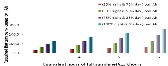
Figure 2:
Variation in required battery bank capacity for different mode of operations using presented
modified method of minimum battery sizing for 2kWp PV system.
VII.MINIMUM BATTERY SIZING WITH MODIFIED AND CONVENTIONAL METHOD:COMPARATIVE ASSESSMENT This section represents comparative assessment by illustrating the required minimum battery bank capacity using modified battery sizing and conventional battery sizing method together. Table 1 represents estimation of minimum battery size for 2 kWp stand-alone PV system for different mode of operations using conventional method with the consideration of battery autonomy as N=1. Here, N represents battery autonomy or multiplying factor of connected load Ah (day and night) during 24 hours and determine total of actual load Ah (for day and night) that battery can serve without day time charging. Consideration of more battery autonomy will cause over sizing problem, which in turn increase the cost and maintenance of battery in PV system. Khouzam (1994) [21] has noted that an oversized battery may eliminate the need for a charge controller in the PV system.
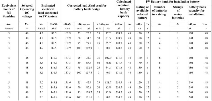
In conventional method of battery sizing estimated battery bank capacity (in Ah) is obtained same irrespective of all different connected load distribution during day and night hours(here presented in terms of different % of total Ah load for day and night time separately). For example as shown in Table 2, in conventional method of minimum battery sizing (for N=1; multiplying factor of one day and night load Ah), for connected load demand of 25% in night and 75% in day, the required battery bank capacity is estimated 214.5 Ah. While for connected load distribution of 75% in night and 25% in day, battery capacity is obtained same 214.5Ah. Here it is found that for all other combination of load distribution during day and night, required battery bank capacity and installed battery bank capacity is estimated same as 214.5 Ah and 240 Ah respectively.
Whereas in modified method estimated required battery size vary with different load distribution during day and night and significant reduction in required and installed battery size capacity is observed with particular day and night connected load distribution as per need of particular application. For example as shown in Fig. 1 equivalent hours of full sunshine of 5 hours per day and battery autonomy n=1 ( i.e. multiplying factor of one night load) Ah, required minimum battery capacity based on night load utilization demand is estimated 53.6Ah for connected load distribution of 25% in night and 75% in day. For load distribution of 50% in night and 50% in day required minimum battery capacity is estimated 107.2Ah, and for connected load distribution of 75% in night and 25% in day battery capacity is obtained 160.9Ah. Whereas, installed battery capacity as presented in the Table 1 have been calculated 120Ah,120Ah and 180Ah respectively for different day and night load distributions, which is normally higher as this depends up on the selected commercially available battery size.
Volume 3, Issue 4, 2016
40 .
Figure 3: Variation in required battery bank capacity for 2kWp PV system using conventional and modified method of minimum battery sizing for different mode of operations
.
In this regard it can be concluded that the battery sizing evaluation using conventional method which is normally based on to serve both connected day and night load Ah requirement, will always estimate oversized battery bank for all kind of weather conditions throughout the year even for clear days also. Though it has already been discussed that the during clear day conditions connected day load is served by PV array power only whereas battery is used to serve night load requirement only. In India out of 365 days in a year, there are almost 275-300 clear days and required battery size evaluated from conventional method of for all kind of PV applications causes oversized batteries for PV system throughout the year.
VIII. CONCLUSIONS
This paper presents a comparative assessment of estimating minimum battery sizing for given rated power of stand-alone PV (SAPV) system for different mode of operations using conventional battery sizing method and proposed modified minimum battery sizing method based on night load demand. Assessment shows that for the PV applications where connected night load is equal or less than 50% of the connected day load, then the required minimum battery bank capacity evaluated by using modified method for battery sizing is obtained almost 50 % or less as compare to the minimum battery capacity estimated from conventional method for battery sizing. Variation in minimum battery size based on night load demand and peak sunshine hours conditions have been suggested. This shows that the installation places of PV system and connected load utilization of PV system during night time will affect the required battery sizing significantly for particular PV application. Therefore, the reader is urged to consult necessity of connected load utilization demand as per day and night operating conditions for a particular application and location of installed PV system to select correct peak sunshine hours when seeking a optimal sizing of SAPV battery bank to obtain minimum cost and maintenance. Suggested modified method of minimum battery sizing on the basis of night load requirement is more efficient, useful and cost effective in case of hybrid PV system applications because system reliability can be improved if a controllable additional power source or backup system is used with less costly PV system to avoid critical operational conditions.
hEFS=3
hEFS=4
hEFS=5
hEFS=6
R
e
q
u
ir
e
d
b
at
te
ry
b
an
k
ca
p
aci
ty
in
A
h
Night load Ah distribution in %
Volume 3, Issue 4, 2016
41
Table 2:
Estimation of optimal battery capacity of PV system for different mode of operations using conventional method
PV Capacity=2kWp ;(DoD)max=0.8 ;Battery autonomy(N)=1( multiplier of one day & night load Ah).Equivalent
hours of
full
Sunshine
Selected
Operating
DC
voltage
Estimated
electrical
load connected
to PV System
Corrected load Ah/d used for
battery bank design
Calculated
required
battery
bank
capacity
PV Battery bank for installation battery
Rating of
available
selected
battery
Number
of batteries
in a string
Strings
of
series
batteries
Battery bank
capacity for
installation
hEFS VDC El (Ah/d)L (Ah/d)c (Ah)night_load ( Ah)day_load (Ah)BB VBB (Ah)b Vb Nb Ns (Ah)inst V inst Hours/d V kWh/d Ah/d Ah/d in % Ah in % Ah Ah V Ah V Ah V
3 48 4.2 87.5 102.9 25 25.7 75 77.2 128.7 48 120 12 4 1 120 48
3 48 4.2 87.5 102.9 50 51.5 50 51.5 128.7 48 120 12 4 1 120 48
3 48 4.2 87.5 102.9 75 77.2 25 25.7 128.7 48 120 12 4 1 120 48
3 48 4.2 87.5 102.9 100 102.9 0 0.0 128.7 48 120 12 4 1 120 48
4 48 5.6 116.7 137.3 25 34.3 75 102.9 171.6 48 180 6 8 1 180 48
4 48 5.6 116.7 137.3 50 68.6 50 68.6 171.6 48 180 6 8 1 180 48
4 48 5.6 116.7 137.3 75 102.9 25 34.3 171.6 48 180 6 8 1 180 48
4 48 5.6 116.7 137.3 100 137.3 0 0.0 171.6 48 180 6 8 1 180 48
5 48 7.0 145.8 171.6 25 42.9 75 128.7 214.5 48 120 12 4 2 240 48
5 48 7.0 145.8 171.6 50 85.8 50 85.8 214.5 48 120 12 4 2 240 48
5 48 7.0 145.8 171.6 75 128.7 25 42.9 214.5 48 120 12 8 2 240 48
Volume 3, Issue 4, 2016
42
References
[1] K. Ledjeff , “Comparison of storage options for photovoltaic system. International Journal of Hydrogen”, Energy,vol. 15,pp. 629-633,1990.
[2] A. Jossen ,J. Garche , DU Sauer ,Operation conditions of batteries in PV applications, Solar Energy,vol. 76 :pp.759– 769,2004.
[3] P.P. Groumpos, N.T. Koussoulas, An optimal sizing method for stand-alone photovoltaic power systems. Solar Energy,vol.38(5), pp.341–351,1987.
[4] M. Egido, E.Lorenzo, The sizing of a stand-alone PV systems: a review and a proposed new method. Solar Energy Material and Solar Cells,vol. 26,pp.51–69,1992.
[5] A.A.Lazou , Papatsoris AD, The economics of photovoltaic stand-alone residential households: A case study for various European and Mediterranean locations,Solar Energy Materials & Solar Cells , vol. 62,pp. 411-427,2000.
[6] R. Posadillo , R.L.Luque , A sizing method for stand-alone PV installations with variable demand,Renewable Energy,vol. 33, pp. 1049–1055,2008.
[7] M.Sidrach-de-Cardona, L.L.Mora Lo´ pez, A simple model for sizing stand alone photovoltaic systems. Solar Energy Material and Solar Cells 55:199–214,1998.
[8] L. Barra , S.Catalanotti , F.Fontana , F.Lavorante , An analytical method to determine the optimal size of a photovoltaic plant. Solar Energy,vol. 33,pp.509-514,1994.
[9] B.Bartoli , V. Cuomo, F.Fontana, C.Serio , V.Silvestrini , The design of photovoltaic plants: an optimization procedure. Applied Energy 18(3), pp. 37–47,1984.
[10]L.L. Bucciarelli ,Estimating loss-off-power probabilities of stand-alone photovoltaic solar energy systems. Solar Energy,vol. 32, pp. 205–209,1984.
[11]C.Rydh, Sadden B. ,Energy analysis of batteries in photovoltaic system, PartI: performance and energy requirements.Energy conversion and management ,vol.46(11),pp.1957-1979,2005.
[12]J. Samimi ,A. Soleimani ,M.S. Zabihi , Optimal sizing of photovoltaic systems in varied climates,Solar Energy, vol.60(2), pp.97-107,1997.
[13]E.S. Gavanidou , A.G.Bakirtzis , Design of a stand-alone system with renewable energy sources using trade off methods, IEEE Transactions on Energy Conversion , vol.7(1),pp.42–48,1992.
[14]M.Salameh Ziyad , S.Borowy Bogdan ,Methodology for optimally sizing of the combination of a battery bank and PV array in a wind/PV hybrid system. IEEE Transactions on Energy Conversion, vol.11(2),pp.367–375,1997.
[15]B. Ai ,H.Yang ,H. Shen,X. Liao, Computer-aided design of PV/wind hybrid system. Renewable Energy 28:pp. 1491-1512,2003
[16]C.Riad , R.Saifur, Unit sizing and control of hybrid wind-solar power systems. IEEE Transactions on Energy Conversion, vol.12(1),pp.79–85,1997.
[17]W.D.Kellogg,M.H. Nehrir , G.Venkataramanan , V.Gerez , Generation unit size and cost analysis for stand-alone wind, photovoltaic, and hybrid wind/PV systems. IEEE Transactions on Energy Conversion ,vol13(1),pp.70– 75,1998.
[18]A.M.O.Haruni,M.Negnevitsky,M.E.Haque and A.Gargoom ,A Novel Operation and Control Strategy for a standalone hybrid renewable power system ,IEEE Transactions on Sustainable Energy, vol.4,pp.402-413,2013.
[19]M.Trifkovic , M.Sheikhzadeh K.Nigim and P.Daoutididis , Modeling and control of a renewable hybrid energy system with hydrogen storage,IEEE Transection on control systems technology, vol.22,pp.169-179,2014. [20]R.Sharma , G.N.Tiwari, Technical performance evaluation of stand-alone photovoltaic array for outdoor field
conditions of New Delhi ,Applied Energy,vol. 92,pp.644-652,2012.