Volume 2, Special Issue 1 MEPCON 2015
83 Available online at www.ijiere.com
International Journal of Innovative and Emerging
Research in Engineering
e-ISSN: 2394 - 3343 p-ISSN: 2394 - 5494
Design and Analysis of Snap fit joint in Plastic part
Rohit M. Kshirsagar1
aand D. B. Pawar2
baPG student 1, Dr. Sau. K. G. I. E. T. Darapur, Amravati and India bAssistant professor 2, Dr. Sau. K. G. I. E. T. Darapur, Amravati and India
ABSTRACT:
Snap fits are the simplest, quickest & most cost effective method of assembling two parts. Basically, a molded undercut on one part engages a mating lip on the other. This method of assembly is uniquely suited to thermoplastic materials due to flexibility, high elongation and ability to be molded into complex shapes. In this research paper a 2D model of snap lock is generated in ANSYS software to study the non linear contact analysis between the mating lips. Result generated by the FEA software ANSYS, allows to evaluate and optimize the snap joint prior to committing costly prototypes and tooling.
Keywords: ANSYS, FEA, Non linear contact Analysis, Snap fit, etc
I. INTRODUCTION
Snap fit is formfitting joint which permits great design flexibility. Snap fit is used to fix two parts together in a certain position. Virtually all consumers and industrial products, utilizing plastic molded components, have multiple components attached together with some form of snap fits. This utilization of snap fit joints for plastic molded component provides an easy and cost effective method to attach multiple component assemblies. During assembly, the parts are elastically deformed. Joints may be non-detachable or detachable, depending on design. A typical snap fit joint assembly consists of a cantilever beam with an overhang at the end of the beam. Snap fit joints are made possible because of the inherent flexibility and toughness of modern thermal plastics. Thermal plastics used in products are typically 30 to 100 times more flexible than metals like steel or aluminum. The stiffness of thermal plastic can be altered by adding glass fibers or composites to the base resin. While designing a snap joint, most of the focus has been on making sure that the snap doesn’t break or fracture upon initial insertion. Equally important to snap failure, is the secureness of the snap joint when subjected to loads by the end user or shock and vibration environments found in industrial applications.
The motions required for assembly are also usually simplified, which is beneficial from an ergonomic standpoint. The use of snap-fit features instead of discrete fasteners results in the reduction of the number of different materials in the assembly, which can be helpful for recycling purposes. Snap fits have traditionally been used in toys, small appliances, automotive, electronic field and other consumer products. The figure 1 shows a typical cantilever snap which gives an overview of mating parts.
Volume 2, Special Issue 1 MEPCON 2015
84 II. MECHANICS OF SNAP JOINT
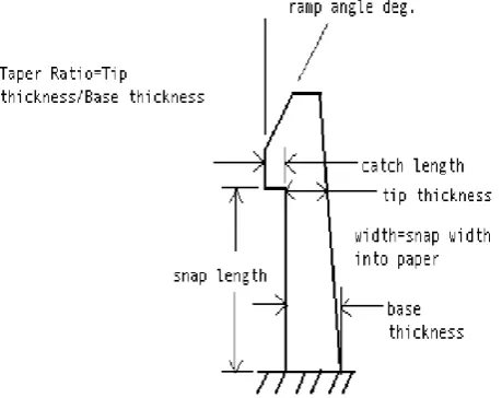
In cantilever snap fit there are some terms like Insertion force, Retention force & locking ratio. Insertion force is the force that needs to be applied in the insertion direction of a snap-fit feature to engage it. Insertion force (Fi) can be expressed as a single maximum value or as a graph of the force versus position relative to the snap-fit feature. Retention force (Fr) is the force that needs to be applied in the separation direction of a snap-fit feature to disassemble it. If designed to be a permanent assembly, disengagement occurs due to fracture, permanent deformation or loss of engagement between the two mating parts. Locking ratio is defined to be the ratio of the maximum retention force to the maximum insertion force of a snap-fit feature. In general a snap fit consist of a cantilever beam with an overhang at the end of the beam. The overhang depth defines the deflection during assembly. The overhang typically has a gentle ramp on the entrance side and a sharper angle on the retraction side as shown in figure2. The small angle at entrance side helps to reduce the assembly effort, while the sharp angle at the retraction side makes disassembly very difficult or impossible depending on the intended function.
Figure 2: Showing Friction cone of a snap fit joint. [9]
The transverse force required to deflect the end of the beam (P) by an amount equal to the overhang depth is determined using Euler-Bernoulli beam theory. This is related to the forces acting on the overhang in the engagement direction to determine the insertion force for the feature. A similar approach is used to determine the retention force. Consideration of the equilibrium of the overhang will show that the end of the beam is subject to an axial load and a moment, in addition to the transverse load. The bending moment in the beam due to the axial component depends on the deflection of the end, rather than being constant. Using the standard beam equations, we can calculate the stress and strain during assembly of the snap beam. If we stay below the elastic limit of the material, we know the cantilever beam will return to its original position. The insertion force of a straight or tapered cantilever beam is calculated by commonly used formula from equation-1. The retention force is determined by the angle of the mating surfaces of the snap fit. To a point, the greater the angle, the greater the holding strength of the snap. This is true only up to the shear strength of the snap and the effects of bending moments applied to the beam, while assembly is equal to overhang depth of beam. The integrity of the assembly can be improved by increasing the overhang depth. Thus the deflection must be optimized with respect to the yield strength or strain of the material. This is achieved by optimizing the beam section geometry to ensure, the desired deflection can be reached without exceeding the strength. The insertion & retraction force will increase with, both stiffness (K) and maximum deflection of the beam (y). It is also important to realize that the Coulomb’s model of friction is also used in the derivation of the above equation.
µ + tan (α)
Fi = P --- (1) 1 - µ tan (α)
Coefficient of friction µ = tan (β) --- (2)
The “Snap Fit Design Guide” By BASF [9] has designed snap fit calculator which utilizes all the beam formulas and calculates the stress or strain values induced by the deflection. They have introduced Magnification factor (Q) which give more accurate prediction of total allowable deflection and strain value for short beams. They have their own online tool which can calculate value for maximum permissible condition. This classical analysis gives results of snap fit pull strength as influenced by factors such as, support stiffness, rake angle, coefficient of friction, and snap lateral stiffness.
III.SNAP FIT DESIGN CONSIDERATION
Volume 2, Special Issue 1 MEPCON 2015
85 area. The stiffness of thermal plastic can be improved by adding glass fiber or composite to the base resin. Creep or more accurately stress relaxation, can result in a reduction of the holding force between the two components connected by the snap fit. To avoid creep there should be relaxation in tension & relaxation in bending. To avoid fatigue failure, choose a material which can perform well in fatigue. This material can be chosen by comparing their S/N curves prior to the snap joint application. Reducing these issues is a major challenge by considering all the parameters in their desired form of a snap fit joint.
The rake angle of snap joint catch is another critical design factor influencing joint secureness. For situations where a part must be easily removed, a positive catch rake angle may be implemented. A positive rake angle provides a lateral load component on the snap beam which allows it to cam out more easily when loaded. Tool makers prefer snaps with positive rake angles because ejection of parts and fabrication of the tool are made much easier. Contrarily, snap fits utilizing negative rake angles require more complex die tooling but have significantly higher pull strengths. Snap fits with negative rake angle catches are analogous to barbs on an arrow head or fish hook. Close examination of standard telephone handset cords reveals a snap fit with a negative rake angle to improve cord secureness.
IV.DEVELOPMENTOF SNAP JOINT IN FINITE ELEMENT MODEL
A two-dimensional finite element model of a tapered snap lock was developed to investigate various factors influencing snap fit pull strength. The model was generated in FEA software ANSYS, which allows nonlinear contact analysis and conduct results for several hundred iterations easily. Provisions were made to adjust the snap catch rake angle, size of snap beam support region and amount of beam taper or taper ratio. Since the deflection behavior of a snap beam is primarily two-dimensional. For efficient results fine meshing is done. Nodes on the outer periphery of this matting region were fixed by edge meshing. Coefficient of friction between the two mating surface was also defined as a material constant elements. A support region around the base of the snap beam was also included in the model to capture the influence of support stiffness. The solutions are progressed by incrementally moving the mating contact surface vertically in the y-direction until total cam-out of the snap beam catch surface occurred. Typical runs on a high end personal computer would required about 200-500 iterations and take about 2-10 minutes.
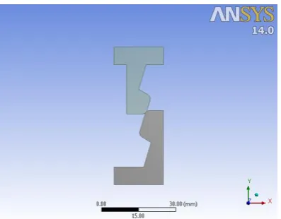
The typical snap lock profile is molded in unfilled or non-reinforce thermal plastic for parametric studies. Snap catch length and modulus of elasticity were held constant. During study factors to be examine were, snap beam taper ratio, snap catch rake angle, snap beam width and snap catch coefficient of friction regarding their influence on snap pull strength. The figure 3 shows the 2D model of snap lock generated in design modeler.
Figure 3: 2D model of snap lock in ANSYS 14.0
V. ANALYSIS SETTING
Volume 2, Special Issue 1 MEPCON 2015
86 Figure 4: Showing Meshing done on the snap lock.
VI.RESULT AND DISCUSSION
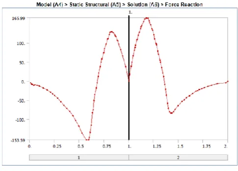
The non linear contact analysis results were required to obtain accurate results of snap push strength and snap pull strength. Figure 5 shows the sequence of deflection during cam-in as the snap is loaded in push direction. From these pictures, it can be noted that the snap catch progressively slides of the mating surface until total engagement occurs. Parametric studies were conducted to determine the influence of snap beam taper ratio, snap insertion angle, snap retention angle and coefficient of friction on snap push strength. The geometric parameters for all cases evaluated were adjusted based on snap insertion model results such that the same bending stress level at the root of the snap beam was achieved for all cases. Parameters held constant for all studies were material modulus of elasticity, beam length, snap catch length and size of the snap support region. The graph generated by the force reaction is shown in the figure. 6. These graph is further generated on varying parameters of the snap lock model and results were generated.
Volume 2, Special Issue 1 MEPCON 2015
87 A baseline model having taper ratio of 0.8, ramp angle or insertion angle of 20º, retention angle 40º and coefficient of friction equal to 0.2 was used as a frame of reference. These three parameters are varying and the range of these parameters was fixed. By studying the results generated the most significant factors influencing are snap beam taper ratio, snap catch angles and snap catch coefficient of friction.
Figure 6: Showing the Force reaction graph.
The snap catch angles play any important role in assembly and disassembly. After studying the results, it may not be possible to assemble parts with ramp angle 45º and high coefficient of friction. It is recommended that ramp angles between 15º to 30º be used and for detachable joints, it is recommended that a retaining angle between 30º to 45º and for permanent joints the retaining angle should be 90º.
VII. CONCLUSION
Wide research has been carried out in the field of design of snap fit joint in plastic parts. From these paper it can be noted that the most significant factor influencing the push or pull strength of a cantilever snap fit are snap beam taper ratio , catch rake angles and coefficient of friction between the mating surface. To optimize plastic molded component utilizing robust snap fit, Finite element analysis software like ANSYS plays a vital role. For further study this approach can be expanded to analyze more complex three dimensional snap fits without fabricating the component their prototypes can be made.
REFERENCES
[1] Anthony F. Luscher, Gary A. Gabriele, Paul R. Bonenberger, and Robert W. Messler Jr. A classification scheme for integral attachment features. In Proceedings of the Society of Plastics Engineers Annual Technical Conference (ANTEC ’95), 1995.
[2] Suat Genc, Robert W. Messler Jr., and Gary A. Gabriele. A systematic approach to integral snap-fit attachment design. Research in Engineering Design, 10(2):84–93, 1998.
[3] Anthony Luscher, Douglas Bodmann, and Gaurav Suri. Assembly of enclosures via integral attachment features. In Proceedings of the Society of Plastics Engineers AnnualTechnical Conference (ANTEC ’98), 1998.
[4] Suat Genc, Robert W. Messler Jr., and Gary Gabriele. Methodology for locking feature selection in integral snap-fit assembly. In Design Engineering Technical Conference(DETC ’97). ASME, 1997.
[5] Suat Genc and Robert W. Messler Jr.and Gary Gabriele. Generating alternative attachment concepts in integral snap-fit assemblies. In International Conference onEngineering Design, 1997.
[6] GE Plastics. GE Engineering Thermolastics Design Guide. Pittsfield, MA, 1997. [7] AlliedSignal Plastics. Snap-fit Design Manual. Morristown, NJ, 1998.
[8] Bayer Corporation. Snap-fit Joints for Plastics. Pittsburg, PA, 1998. [9] BASF Corporation. Snap fit design manual.Wyandotte, Michigan, 2006