Volume 2, Issue 10, 2015
39
Available online at www.ijiere.com
International Journal of Innovative and Emerging
Research in Engineering
e-ISSN: 2394 - 3343 p-ISSN: 2394 - 5494
FPGA Based Vehicle Classification System Using Binary Side
Profile of the Vehicle
Mr. Omkar C. Marathe
a, Dr. Mrs. Shaila Subbaraman
baStudent- M.E. (VLSI & Emb. Sys.), Annasaheb Dange College of Engineering and Technology, Ashta, India. bProfessor (Dept of Electronics Engg), Walchand College of Engineering, Sangli, India.
ABSTRACT:
The paper presents infrared sensor based Portable Automatic Vehicle Classification System. The Infrared transmitters (Light Emitting Diodes) and receivers are installed on vertical poles which are installed on opposite sides of road lane and aligned in such a way that each infrared transmitter is directed to only one infrared receiver. The transmitter and receiver arrays are controlled and synchronized by hardware designed on FPGA. The output of infrared receiver array captured by FPGA gives the side profile of the vehicle passing through lane, which is used by system designed on same FPGA to calculate vehicle parameters such as height, length and number of axles etc. These physical parameters are used by classification block designed on same FPGA to perform classification of the vehicle. The system when tested can classify the vehicles with more than 90% of accuracy.
Keywords: FPGA, binary side profile, infrared , delays, low power, real time.
I. INTRODUCTION
Vehicle count and classification data is used by traffic controlling authority to either improve traffic conditions on that road or provide an alternative in case of an excessive amount of traffic. It can also be used at the toll collection booth where class of the vehicle is required for charging the appropriate toll to the user. Though manual vehicle classification method seems to be less complicated with minimum investment, it is prone to human errors and bad practices. This leads to the necessity for adapting ‘Automatic Vehicle Classification System (AVCS)’. An AVCS consists of sensor devices installed in a lane to record the physical characteristics of vehicles and a processing unit to aggregate the input and interpret it to assign a class to each vehicle passing through the lane. The conventional AVCS consist of the computer based system which employs a set of sensors that capture vehicle parameters and performs classification of vehicle with the help of specially designed software.
The low power is an important requirement of an automated system. The low power implementation leads to the adaptation of portable systems. Developing such a portable systems using microprocessor requires implementing classification algorithms on general purpose processor by means of its instruction set which makes the program complex and time consuming. This motivates for implementing Field Programmable Gate Array (FPGA) based system for automated vehicle classification by means of a dedicated hardware. The input used by the proposed system is a binary side profile of the vehicle, which can be recorded by Infrared Sensor based system as explained in [8].
II. LITERATUREREVIEW
Volume 2, Issue 10, 2015
40
III.SYSTEMDESIGN
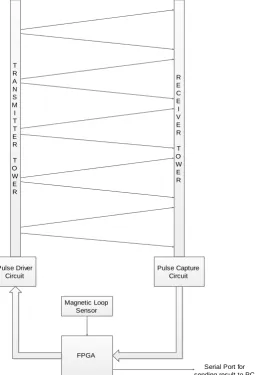
Consider Fig. 1 which shows the hardware architecture of the system. The system consists of IR Transmitter array, IR Receiver array, IR Pulse driving circuit, IR Pulse capturing circuit and FPGA. The system on FPGA, apart from calculation & classification, performs the synchronization between IR Transmitter & Receivers. The timing & control block then triggers hardware units for vehicle parameters calculation, which calculates various vehicle parameters like vehicle length, vehicle maximum height, number of axles, distance between axles etc.
Figure 1. Architecture of the System designed on FPGA.
When the entire vehicle is passed, the timing & control unit stops triggering-capturing-calculation operations, and triggers hardware unit for vehicle classification. The classification hardware unit, after classification & counting is completed, triggers the serial transmitter designed on the same FPGA chip, which transmits the classification data stored in temporary storage memory to the computer system which contains the vehicle classification database.
Consider Fig. 2 which represents the pulse with 38kHz frequency generated at I/O pin of FPGA used for triggering the Infrared Transmitters.
T R A N S M I T T E R
T O W E R
R E C E I V E R
T O W E R
Pulse Driver Circuit
Pulse Capture Circuit
FPGA
Serial Port for sending result to PC Magnetic Loop
Volume 2, Issue 10, 2015
41
Figure 2. Pulse generated at FPGA I/O Pin.
This pulse drives the driving circuit of Infrared Transmitter. The similar pulse is generated at 10 different pins of FPGA that trigger 10 Infrared Transmitters in an array.
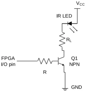
A. Infrared Transmitter Driving Circuit
Fig. 3 represents the circuit for driving IR Transmitters. It is a transistorized switching circuit which is capable of transmitting train of pulses with 50% duty cycle. The train of pulse is generated by FPGA I/O pin with reference to 38 kHz frequency which is receipt able at IR Receiver side. This train of pulse is generated in synchronization with the clock signal & active vehicle presence signal. The similar circuit is used for driving other IR Transmitters in an array. All IR Transmitters are triggered simultaneously with different FPGA I/O pins.
Figure 3. Driving Circuit for Infrared Transmitter.
The load resistor value in above circuit is calculated using following formula,
𝑅𝐿=
𝑉𝐶𝐶− 𝑉𝑓
𝐼𝐿
(1)
where, RL is a load resistor, VCC is the supply voltage, Vf is the forward voltage drop in Infrared LED and IL the current
flowing through load (IR LED).
Based on experiments conducted on triggering circuit in the laboratory provided by RLARD, considering VCC=5 V,
Vf=0.6 V, IL=20 mA
𝑅𝐿=
5 − 0.6
20 ∗ 10−3= 220Ω (2)
B. Infrared Receiver Capturing Circuit
VCC
FPGA I/O pin
RL
IR LED
R
Q1 NPN
Volume 2, Issue 10, 2015
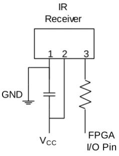
42 Fig. 4 shows the circuits for Infrared Receiver, which contains TSOP31238, infrared receiver module, resonating capacitor and spike suppressing series resistor. TSOP31238 is a receiver module for infrared based system. A PIN diode and a preamplifier are assembled in a single epoxy package that contains an IR filter. This module contains internal filter for PCM frequency. It provides shielding against Electro-Magnetic Interference. It provides immunity against ambient light, thus making the system independent of the light levels during different durations of the day. It is insensitive to supply voltage ripple and noise. Also it is optimized to suppress almost all spurious pulses from energy saving lamps like CFLs. Fig. 4 shows the circuits for Infrared Receiver, which contains TSOP31238, infrared receiver module, resonating capacitor and spike suppressing series resistor. TSOP31238 is a receiver module for infrared based system. A PIN diode and a preamplifier are assembled in a single epoxy package that contains an IR filter. This module contains internal filter for PCM frequency. It provides shielding against Electro-Magnetic Interference. It provides immunity against ambient light, thus making the system independent of the light levels during different durations of the day. It is insensitive to supply voltage ripple and noise. Also it is optimized to suppress almost all spurious pulses from energy saving lamps like CFLs.
The infrared signal generates an equivalent current in the photo PIN diode. The DC part of the signal is blocked in the bias circuit and the AC part is passed to amplifier followed by an automatic gain-control amplifier and an integrated band pass filter. The demodulated output signal can be directly interfaced to FPGA I/O pin for further processing. The digital output signal has an active low polarity and consists of an envelope signal of the incoming optical pulse, without the carrier frequency. FPGA I/O pins collect all sensors output in receiver array and sends it to on-chip calculation and classification units
Figure 4. IR Receiver Circuit
When there is no any signal transmitted by infrared transmitter, the output of the receiver is in high state with a voltage level equal to that of supply voltage. When transmitter is triggered with a pulse train of 38 kHz frequency, at corresponding instance the output of receiver is active with a low voltage level. In presence of any obstacle, the path from transmitter to receiver is blocked, and the output voltage level is held at high voltage. Thus when vehicle is at particular sensor position, it blocks transmitter-receiver path giving logic-1 at receiver output. If vehicle is not present at particular sensor position, the path is available, which gives logic-0 at receiver output. The receiver output corresponding to each triggering instance is copied into FPGA and used by the classification unit designed inside FPGA.
The system designed inside FPGA synchronizes transmitter and receiver circuits in such a way that the I/O pins of FPGA read the receiver output data when the transmitters are triggered. This allows capturing receiver output which represents the vehicle vertical position at particular triggering instance.
C. Vehicle Parameter Calculation & Classification
The ‘Infrared trigger’ pulse and the ‘read’ signals are generated every 20 milliseconds when the vehicle is present. By considering a delay for copying receiver output into FPGA, this unit triggers ‘enable’ signals for ‘Height Calculation’ unit, ‘Length Calculation’ unit and ‘Axle Calculation’ unit. Thus before generating next sequence of ‘infrared trigger’ and ‘read’ signals, hardware units on FPGA perform their respective operations of height calculation, length calculation and axle calculation. It performs different operations on input data which is vehicle binary side profile to calculate vehicle parameters like vehicle length, vehicle height, number of axles, distance between axles etc. These parameters are further used by the system to carry out classification of vehicles. The classification result is stored in internal storage memory before it is transferred to external computer system where complete classification database is maintained. The system contains internal serial transmitter which serially transfers the classification and count data to external computer system. All the sub-systems in this system are synchronized by “Timing & Control Circuit”.
The values of different vehicle parameters are given to the processing unit that performs operations of vehicle counting and classification. This unit is triggered by ‘timing and control’ unit. When ‘vehicle presence’ signal from magnetic loop sensor makes a transition from high to low, timing and control unit generates a signal- ‘classify’, which triggers the hardware unit for vehicle counting and classification. This unit uses a set of parameters calculated by different hardware units on FPGA to perform classification of the vehicle.
IR Receiver
1 2 3
FPGA I/O Pin VCC
Volume 2, Issue 10, 2015
43
IV.SYSTEMIMPLEMENTATION
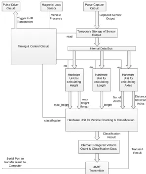
Consider Fig. 5 which represents the internal architecture of the system implemented on FPGA. It shows various hardware units which are designed on the chip, and perform different operations.
Figure 5. Internal Architecture of the System designed on FPGA
‘Height Calculation Unit’, ‘Length Calculation Unit’ and ‘Axle calculation unit’ are the units in the system that work concurrently. These units use same vehicle binary sequence to calculate height, length and axles of vehicle that passes through the lane. ‘Vehicle Classification Unit’ performs classification of the vehicle from values calculated by hardware units.
All the hardware units were first designed using a VHDL code, synthesized in Xilinx ISE environment. After following standard process for implementation in Xilinx ISE tool, the ‘bitstream’ file was generated which can be downloaded into FPGA.
V. RESULTS
After the completion of implementation stage, the bit-stream file of the design was used for configuration of target FPGA device. The FPGA based system was tested with IR Sensors, which give the binary side profile of the passing vehicle.
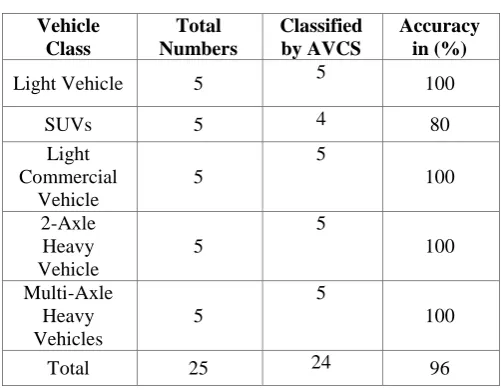
Serially transmitted result was received on computer system with ‘Docklight’ tool installed on it. It is a GUI based tool which is capable of transmitting and receiving data bytes from other systems with standard baud rates based on user applications. The total vehicle count and vehicle class result given by the system was compared with the actual count and class of passing vehicles. Consider Table I, which indicates the accuracy of the classification and counting system was found to be 96%, which is more than the percentage (90%) which was considered as criteria while finalizing the objective of designing the portable system using FPGA.
Pulse Driver Circuit
Pulse Capture Circuit Magnetic Loop
Sensor
Timing & Control Circuit
Temporary Storage of Sensor Output
Hardware Unit for calculating
Height
Hardware Unit for calculating
Length
Hardware Unit for calculating
Axles
Hardware Unit for Vehicle Counting & Classification.
Internal Storage for Vehicle Count & Classification Data.
UART Transmitter
Internal Data Bus
en en en
max_height
max height
length length
No. of Axles
Distance between Axles
classification
Classification Result
Transmit Result Vehicle
Presence
Captured Sensor Output Trigger to IR
Transmitters
read
Serial Port to transfer result to
Volume 2, Issue 10, 2015
44
Table 1. Vehicle Classification Accuracy.
Vehicle Class
Total Numbers
Classified by AVCS
Accuracy in (%)
Light Vehicle 5 5 100
SUVs 5 4 80
Light Commercial
Vehicle
5
5
100
2-Axle Heavy Vehicle
5
5
100
Multi-Axle Heavy Vehicles
5
5
100
Total 25 24 96
As system is implemented with digital logic, there are combinational delays associated with each hardware unit. These delays for every unit can be analysed after synthesis of the hardware unit. These delay values play important role in proving ability of designed system for real time applications. Consider Table II, which contains maximum combinational delays for different hardware units in designed system.
Table 2. Combinational Delays for Different Hardware Units
Hardware Units Delay (ns)
Height Calculation Unit 6.52 Length Calculation Unit 3.84 Axle Calculation Unit 3.78 Vehicle Classification Unit 5.63
The hardware units for height, length and axle calculation work concurrently independent of each other. The input data for calculations is given to these units in parallel manner. Thus the delay for calculation of all three parameters is the maximum delay among the concurrent hardware units which is 6.52 ns. The time available for calculating these parameters is 20 milliseconds. Thus all parameters for current sequence are calculated before next sequence is arrived and given for calculation. The maximum combinational delay for vehicle classification hardware is 5.63 ns. Thus the classification result calculated in 5.63 ns after entire vehicle is passed.
VI.CONCLUSIONS
From the results given in Table I, the classification accuracy of the system implemented on FPGA is 96%, which is more than the percentage finalized in the objectives of the proposed work. The higher percentage of the classification accuracy makes the system suitable for applications requiring reliable operations like automated toll booth and automated traffic controlling systems.
The combinational delays for different hardware units are presented in Table II. Since all the hardware units complete the calculation of vehicle parameters before arrival of next sequence of binary side profile, all the parameter values are available as soon as the entire vehicle profile is received. The combinational delay of vehicle classification unit is 5.63 ns, thus vehicle classification is complete in 5.63 ns once entire vehicle side profile is received. The lower combinational delays associated with FPGA based system makes the system suitable for the real time applications.
The presented work can be used as the basic infrastructure for the automated traffic controlling systems and automated toll collection systems. The traffic controlling and toll collecting authorities can use this system in extension with internet connection facility to upload result on servers. Once the result is available on the servers, it could be used by the concerned authorities for either automatic traffic monitoring and controlling or the automatic toll collection systems, which can substantially eliminate the traffic interruptions at the toll collecting stations.
ACKNOWLEDGMENT
Volume 2, Issue 10, 2015
45
REFERENCES
[1] Janusz Gazda, Ryszard Sroka, Marek Stancel, Andrej Wadja, Tadeusz Zeglen, “A Vehicle Classification Based on
Inductive Loop Detectots” in IEEE Instrumentation and Measurement Technology Conference, Budapest 2001.
[2] Saowaluck Kaewkamnerd, Ronachai Pongthornseri, Jatuporn Chinrungrueng, Teerapol Silawan, “Automatic Vehicle Classification Using Wireless Magnetic Sensor,” in IEEE International Workshop on Intelligent Data Acquisition and
Advanced Computing Systems, Italy, 2009.
[3] Bong-gu Lee, Jung-han Kim, “Algorithm for Finding the Moving Direction of a Vehicle Using Magnetic Sensor,” in
IEEE 2011.
[4] Saber Taghvaeeyan, Rajesh Rajamani, “Portable Roadside Sensors for Vehicle Counting, Classification and Speed
Measurement,” in IEEE Transactions On Intelligent Transportation Systems, 2013.
[5] P.M. Daigavane, Preeti R. Bajaj, M.B. Daigavane, “Vehicle Detection and Neural Network Application for Vehicle
Classification”, in IEEE International Conference on Computational Intelligence and Communication Systems, 2011.
[6] C. Chai, Y. D. Wong, “Automatic vehicle classification and tracking method for vehicle movements at signalized intersections” IEEE Intelligent Vehicles Symposium, 2013.
[7] Antonio Carlos Buriti da Costa Filho, Joao Pereira de Brito Filho, Renato Evangelista de Araujo, Clayton Augusto Benevides, “Infrared-based system for vehicle classification”, in IEEE MTT-S International Microwave &
Optoelectronics Conference, 2009.
[8] Hemanshu Khatri, Sunil Somani, “Infrared-Based System for Vehicle Axle Counting and Classification”, in 8th IRF
International Conference, Pune, 2014.
[9] Omkar C. Marathe, S. Subbaraman, “Portable Vehicle Classification System using FPGA”, International Journal of