34
Cavitation Process and the Performance of Some Ferrous
and Non-Ferrous Alloys
M. Farzam∗
Faculty of Petroleum Engineering, Petroleum University of Technology, Ahwaz, Iran
Abstract
In this research an extensive literature search into the mechanism of cavitation dynamics and its consequences was conducted. A cavitation venturie rig was designed and constructed, and the cavitation number was checked mathematically. A new camera technique was developed to capture the cavitation cloud. Carbon steel (AISI 1020), stainless steel (AISI 304 and 316), ferritic alloy steel (B1274), brass (C27000), phosphor bronze (C51000) and aluminum bronze (C60800) test pieces were prepared and tested in the venturie tube. Aluminum bronze was the most and carbon steel the least resistant of these alloys, the measured mechanical properties could not systematically be correlated with cavitation resistance. The microscopic examinations showed that cavitation induced plastic deformation had caused the misalignment of polishing lines. A field study into the susceptibility of an Iranian sugar cane company’s centrifugal pumps showed that deviation from the manuals hydraulic settings caused cavitation and that the gray cast iron had a poor resistance. Besides the venturie tube, other configurations were considered, of which an oil industry choke valve was constructed and examined for cavitation.
Keywords: Cavitation, cavitation-erosion, cavitation cloud, cavitation resistance alloy, cavitation number, cavitation camera technique
∗ Corresponding author: E-mail: [email protected]
Introduction
The literature search showed that research on cavitation goes back many years and numerous scientists have studied the cavitation phenomenon [1-4]. Cavitation can be simply considered as a local boiling effect in a fluid undergoing dynamic pressure reductions. When the local pressure falls below the vapor pressure the fluid may undergo a phase change from liquid to gas. This is an endothermic process and will therefore be accompanied by a temperature
Iranian Journal of Chemical Engineering, Vol. 5, No. 1 35 when the fluids vapor pressure is reached due
mainly to a poor engineering design and is different to other phenomena such as choke, surge, transition and hammering. As with any phase change the cavitation process is influenced by the presence of seed particles; dissolved gas and suspended solids. Cavitation cluster contains millions of collapsing bubbles which, given the speeds involved in the process [5], can cause damage in a short time. It is not the bubble itself which is damaging but rather the collapse of the bubbles when the pressure rises above the vapor pressure. The implosion of a bubble causes a small but measurable shock pulse. When such shock pulses are multiplied many times, noise and vibration are produced.
Karimi [5], through the years, has conducted a concise literature survey on cavitation; its physics, damage and prevention.
Cavitation erosion is controlled by the fluid speed and pressure, which can be correlated by the cavitation number Cv:
2 2( - ) Cv =
ρ
Po Pv V
Where Po = ambient pressure Pv = vapor pressure
ρ = fluid density V = fluid velocity
Also, in the case of centrifugal pumps cavitation happens at a given N.P.S.H. (net positive suction head):
-N.P.S.H. = Po Pv - Zsγ γ Where γ = viscosity Zs = suction head
Considering Cv, it must fall below a certain value for cavitation to begin. On the other hand, comparing various engineering sections with each other, the lower the Cv the less the possibility of cavitation erosion [6]. In the case of N.P.S.H., for cavitation to begin its value it must not exceed a specific
value. The Cv and N.P.S.H. can be related to one-another [22], never the less, if low static head is not reached, (vapour pressure) cavitation will not happen, however, increasing temperature will increase cavitation [23].
Thus fluids physical properties and the container’s (substratum) design and physics effect the process. The electrochemistry of the substrate and the reactivity of the fluid will also effect the extent of cavitation. The erosion-corrosion parameters and their interaction with containers material pro-perties are complicated [7,8]. Up to now attempts to correlate surface hardness, strength and toughness have failed [9], while surface morphology also looks to be related [10,11].
Experimental cavitation tests are conducted by the following methods:
-vibratory device, -rotating disc,
-venturie test section.
Because of the varying duration of the above testing methods the volume of research reported decreases in the order written above. As the conditions of the above tests are not totally similar, any relative comparison and interpretation must be conducted with caution.
To conduct the above tests standards are available; e.g., ASTM G32, D2809.
Cavitation erosion is time dependent and sometimes starts after an incubation period and accelerates to a maximum value before reaching a steady state [12] (Fig. 1). The deceleration erosion period involved sometimes could be cyclic (serration), or rapidly decreasing, depending on the material and the test procedure (Fig. 1).
36 Iranian Journal of Chemical Engineering, Vol. 5, No. 1
Figure 1. Cavitation erosion-corrosion characteristics [12]
Cavitation erosion inhibition could not only be conducted by changes in design (the decrease in the cavitation number) and the use of resistant materials, but also with certain fluid treatments such as increased viscosity.
Shock absorbent surfaces (e.g. rubber) could dampen the hammer force of the collapsing bubbles.
Cavitation’s detectable vibration is used to measure the extent of damage [13]. Other workers [14,17] have used the X-ray diffraction technique to acknowledge the presence of cavitation by monitoring the change in sub-surface residual stress. This is crucial in studying the possibility of any damage prior to the incubation period.
The purpose of this study was to construct a
cavitating venturie apparatus, a camera technique and make a comparative investiga-tion into different alloys susceptibility.
Experimental Procedures
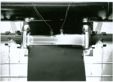
A cavitation rig, using the basic principals (the Bernouli’s equation), was designed and constructed (Fig. 2). All calculations, sizes, design features, material selection and ordering was conducted by myself (during a research period at Heriot-Watt university in Scotland). Pure tap water at ambient temperature was circulated via a centrifugal pump at the maximum flow rate of 90 m^3/h. The venturie working section (Fig. 2, 3) made of Perspex glass was designed to withstand flows with the maximum velocity of 35 m/s at 2.5 m head.
Tb; incubation period Notice the various forms of Reported cavitation
Iranian Journal of Chemical Engineering, Vol. 5, No. 1 37
Figure 2. The constructed cavitation rig
Figure 3. The Venturie working section
1- venturie working section
2. water tank 1 m3
3- chock valve 4- pump
5- control valve 6- tube
38 Iranian Journal of Chemical Engineering, Vol. 5, No. 1 A total of one meter cubed tap water stored
in a reservoir, untreated, went round the circulating rig. Using a macro-lense 35 mm camera the inception of the bubbles vis-à-vis the cavitation cloud was studied. Please note it took 6 months to develop a photographic technique to capture the cloud.
Four anti-corrosion pressure transducers were installed (Fig. 2, 3) and used to determine the exact speeds at different sections of the rig and venturie.
In the next stage alloys such as carbon steel AISI 1020, stainless steels; AISI 304 and 316, ferritic alloy steel B1274, brass C27000, phosphor bronze C51000 and aluminum bronze C60800 were inserted in the expansion side of the venturie tube where the cavitation cloud was present. Using a round cylindrical fixture, metal pieces with the hold tightly following dimensions were in place; 10 x 2 x 0.5 cm.
All the metal pieces were ground in the workshop before being polished with a SiC paper grade 600 (Fig. 4); notice the polishing
parallel scratch lines.
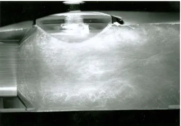
Figure 5 shows the cavitation generated cloud consisting of millions of bubbles, notice the phenomenon is taking place in the expansion side of the venturie tube; as the fluid velocity increases in the contraction side, the static pressure falls below the vapour pressure, and a bubble forms. The many produced bubbles in the expansion side, due to the surrounding pressure, implode, resulting in the formation cloud. According to other research findings (Fig. 1) and the fact that the cavitation damage was time dependent, alloys initially exposed for a few minutes up to 40 minutes exposure, it was noticed that no real damage was recorded. Following trial and error tests and in accordance with previous works [e.g. 19], all the alloys were exposed to the cavitation cloud for the time duration of 60 and 120 minutes. Using light microscopy the metal surface topography were further studied in detail and compared with the original ones (Figs 4 and 6 to 14).
Figure 4. Original alloy surface finish before being cavitated, alloy AISI 304 Mag. x 100
Iranian Journal of Chemical Engineering, Vol. 5, No. 1 39
Figure 5. Cavitation generated cloud
A choke valve (also known as pressure valve) was made from Perspex and was added online to the rig (Fig. 2). By controlling its settings, the investigation into the possibility of cavitation in the choke valve was studied (Fig. 18, 19).
The possibility of the mechanical properties correlation with the extent of cavitation damage was conducted by hardness and tensile testings (Table 1).
An argon laser was used to intercept the cavitation bubbles with the prior intention of numbering and sizing (Fig. 18).
Besides the above research, an investigation into the cavitation erosion-corrosion of sugar cane industries centrifugal pumps was carried out by the author in Iran [15]. In which case visual inspection, light microscopy and hardness testing were conducted (Fig. 16,17). Also, the X-ray technique was used as a non-destructive method to work out the integrity of cast iron pump impellers. A hydraulic and
hydro-dynamic study of such pumps were carried out [21,22].
Results and Discussion
Figure 5 shows the cavitation cloud which consists of millions of bubbles. Due to the implosion of bubbles, noise and vibration were produced. This was due to the shock force effect.
40 Iranian Journal of Chemical Engineering, Vol. 5, No. 1 place, and mass loss due to erosion happens.
Figure 4 shows the original stainless steel (AISI 304) in its polished state, notice the 600 grade polishing paper’s parallel lines. This conditioning was the same for all the test alloys before their insertion (the fixture held all the 7 alloys at the same time) into the cavitating venturie. All the alloys were micro-photographed before insertion, the
only difference noticed visually was their color. Figure 6 and 7 show alloys carbon steel (AISI 1020) and stainless steel (AISI 304) in their original state.
After 60 min exposure to the cavitation cloud it was noticed that carbon steel (AISI 1020) was the most damaged alloy (Fig. 8), while the aluminum bronze (C60800) the least (Fig. 9).
Figure 6. Carbon steel (AISI 1020) polished with 600 SiC paper Mag. x 80.
Iranian Journal of Chemical Engineering, Vol. 5, No. 1 41
Figure 8. Carbon steel after 60 min exposure is most damaged Mag. x 200
42 Iranian Journal of Chemical Engineering, Vol. 5, No. 1 As the Rockwell hardness (RB) and the
tensile strength value of the alloys under examination were measured it was noticed that the carbon steel had the lowest tensile strength; 395 MPa, but a moderate hardness
value of 89 (Table 1). The comparative tabulation of tested alloys, hardness and tensile tests were taken in the original state (note; cavitation resistance increased orderly from alloy a to g):
Table 1. Hardness and tensile strength of the tested alloys
Test Material Rockwell Hardness Value; RB Tensile Strength MPa
a- Carbon Steel (1020) 89 395
b- Brass (C27000) 63 673
c-Ferritic Steel (B1274) 87 479
d- Stainless Steel (304) 80 510
e- Stainless Steel (316) 85 517
f- P-Bronze (C51000) 86 455
g- Al-Bronze (C60800) 95 759
For the ferritic alloy (B1274) a similar fate was recorded, but when compared with C-Steel the attack was less severe (Fig. 10). The decrease could be due to the increased alloying, therefore the increased tensile strength and hardness.
Brass (C27000) was also extensively attacked in a manner that made it difficult to rank, and worse, the ferritic alloy (Fig. 11) showed a localized attack.
Light microscopy examination showed that stainless steels 304 and 316 were only mildly attacked, and in the worst places the surface only exhibited shallow pits (Fig. 12, 13). The increased resistance is due to increased tensile strengths (Table 1) and the presence
of Ni and Cr as the strengthening and passivating alloys.
Iranian Journal of Chemical Engineering, Vol. 5, No. 1 43
Figure 10. Ferritic alloy (B1274) after 60 min exposure was severely attacked Mag. x 200
44 Iranian Journal of Chemical Engineering, Vol. 5, No. 1
Figure 12. Stainless steel AISI 304 was lightly attacked (pitted) Mag. x 100
Plastic deformation effect
Iranian Journal of Chemical Engineering, Vol. 5, No. 1 45
Figure 14. P-Bronze (C51000) after 60 min exposure showed slight pitting Mag. x 100
Samples Tested in this Work
1- Carbon steel 2- Stainless steel ( types) 3- Ferritic steel 4- Brass 5- P- Bronze 6- Al- Bronze
Figure 15. Ranking of the common alloys according to their 2
2
T .S
46 Iranian Journal of Chemical Engineering, Vol. 5, No. 1 Since none of the usual measurable
mechanical properties discussed above correlate directly, one may consider the following normalized parameter (resilience
number); E S T 2 . 2
Where T.S. is the tensile strength and E the young’s modulus, Figure 15 shows how common alloys are ranked for their resistance to cavitation.
While Al-Bronze showed the least damage (Fig. 9), it fits the previous postulation about mechanical properties as this alloy had the highest tensile strength (759 MPa) and hardness (95). This finding fits the data presented in figure 15, where the relative cavitation resistance of Al-Bronze is taken as 1, and stellite (Ni-Ti) alloy is shown to have the highest cavitation resistance of all the alloys available. Richman et al [16] found, experimentally, that stellite was extremely resistant to cavitation erosion. Gen He et al’s [19] findings about the low cavitation erosion resistance of C-Steel fitted the data generated in this work. Other researchers [9,10] have also conducted cavitation erosion tests on the resistance of stainless steel and cast iron Cr-Mo-Cu alloy, their findings were also in agreement with this research.
During the light microscopic examination of the damaged alloys it was noticed that the
polishing scares had been misaligned, Figure 13 shows this phenomenon (flash-marks in the photo). Other researchers [16,17] using electron microscopy and X-ray diffraction techniques showed that cavitation could produce a metallurgical phase and structural changes such as monoclinic martensite phase transformation, twin-boundary motion, twinning shear, microhardness changes and the production of deformation texture.
All the above alloys were also tested for 120 min but little change in surface morphology, compared to 60 min exposure, was recorded. This could be a sign of reaching some sort of a steady state situation (Fig. 1). Mathias et al’s [17] findings endorsed the time dependency of cavitation. Some researchers suggest that the hammering plastic deformation must have a similar mechanism to low cycle fatigue [16,17]. Chen [18], following his research, suggest that plastic stress deformation is produced during the initial bubble nucleation and growth stage rather than the final implosion stage.
In an another extensive field study on the centrifugal pumps of the Iranian sugar cane industry [15], it was concluded that if the hydraulics hydro-dynamic conditions of such pumps were not met, cavitation erosion-corrosion could damage the pumps parts (Fig. 16).
Iranian Journal of Chemical Engineering, Vol. 5, No. 1 47 As it was noticed after only a few months of
service, the cast iron impellers and the casings were attacked. As a result, the integrity of the pump design was degraded; the pump efficiency was reduced [15]. The circulating fluid was brine water containing sand particles extracted from the artificial water flooding of Khozestan farms which were being rehabilitated for sugar cane farming. Figure 17 shows the microstructure of the impeller’s gray cast iron in its polished and etched state. The fluid approaches the impeller blade with larger and larger angles of incidence altering the velocity and pressure fields inside the impeller. Suction recirculation [22], stall and separation of the fluid leads to reversal flow in the pump. For
such high energy pumps operating below the design levels, cavitation on the blades will lead to pulsation, piping instability and pump viberation.
Blade angle will also effect the inception of cavitation and its damage. Altering the inlet blade angle can reduce the cavitation attack [22].
By increasing the total or local pressure in the system, the distance between the static pressure and vaporization pressure is increased, therefore cavitation may be avoided. However, if water temperature was increased from the Ahwaz room temperature, 30 c to 55 c, the vapour pressure increased from 4.3 kN/m^2 to 15.7 kN/m^2, increasing the possibility of cavitation[23].
Figure 17. The microstructure of the impeller, gray cast iron in its etched state
The measured hardness was only HB = 187 (Brinel) which is near the C-Steel value. As was discussed previously, very low hardness values, cautiously, may be taken as a measure of low resistance to cavitation erosion-corrosion. To improve the situation and extend the service life two suggestions were made. Firstly, all the hydraulics of such
pumps be readjusted according to the manual, secondly impellers material (and casing parts) be changed to Al-Bronze (which were conducted under the authors supervision).
48 Iranian Journal of Chemical Engineering, Vol. 5, No. 1 conditions of a petroleum industry’s well
head choke valve was conducted (Fig. 18). I also tried to apply the laser beam via-a-vis a computer program to statically number the cavitation population.
The core chosen was a 120 degree one (in accordance with a real one), therefore as is noticed in figure 19, it consisted of 3 rows of holes separated by 120 degrees.
Figure 18. the constructed choke valve
Iranian Journal of Chemical Engineering, Vol. 5, No. 1 49 When the piston; the actuator, (Fig. 18,19)
was fully out, flow rate was at its maximum with the highest static and dynamic pressure drop. With the rig’s flow condition described in the experimental section, a cavitation cloud developed in the choke valve. As the piston was traversed forward, the flow rate decreased, cavitaion bubble production emerged with noise and vibration continued. As was gathered through the above results and discussion, to protect against cavitation erosion-corrosion, design (cavitation number and N.P.S.H.) and material selection [24] are the two main important factors to be cosidered. Decreasing the flow rate, increasing the piping diameter, reducing sharp section changes and controlling the cavitation number and net positive suction head are the main design factors to be met. Hard surface laser treatment coating has been [11], surface roughening and dampening may also be applied. Mathias et al [17] suggested that the cavitation process is similar to shot peening, thus by introducing surface com-pressive stresses one may harden the material against cavitation damage. Proper selection of the material; Stellite, Al-Bronze, etc is also suggested, or resistance coatings may be applied [26].
Eliminating the suspended particles and or controlling the fluid electrochemistry may also be used to reduce cavitation erosion-corrosion.
Conclusions
1- If the hydraulic and hydrodynamics conditions are not satisfied cavitation develops.
2- Cavitation cloud can be recorded on film, using the developed special technique. 3- Aluminum bronze (C60800) was the most
resistant of the tested alloys.
4- Carbon steel (AISI 1020) was the least resistant of the tested alloys.
5- Light microscopic studies revealed that the cavitation damage is mechanical. 6- Plastic deformation caused the 600 SiC
grade polishing lines to be misaligned.
7- The mechanical properties hardness and the tensile strength could not be used as a full-proof cavitation resistant ranking. 8- Increased hardness may be taken as
increased resistance against cavitation erosion.
9- Field study on centrifugal pumps showed that deviation from pump’s manual hydraulic settings caused cavitation and that gray cast iron had a poor resistance against cavitation damage.
10-Choke valve in various positions of the actuator showed cavitation.
References
1. Knapp, R.T., Daily, J.W. and Hammitt, F.G., in Cavitation, McGraw-Hill (1970).
2. Pearsall, I.S. in Cavitation, Mills and Boun (1972).
3. Escaler, X., Farhat, M., Avellan, F., Egusqiza, E., Cavitation Erosion Test on a 2D Hydrofoil Using Surface Mounted Obstacles, Wear 254, P441 (2003).
4. Shimizu, S., Tsu Rusaki, K., Hara, M. and Nakagawa, T., Damage Due to Spot Cavitation on Hemispherical Cylindrical Body, Proceeding of 3rd International Symposium on Cavitation, Grenoble France, Volume 2, P163 (1998).
5. Karimi, A. and Martin, J.L., Cavitation Erosion of Materials, International Metal-lurgical Review, Volume 31(1), P1 (1986). 6. Van Der Meulen, J.H.J. and Nakashima, Y.,
A New Approach to Detection of Cavitation on Mechanical Heart Valves, 2nd International Conference on Cavitation, Institute of Mechanical Engineers, Conference Publi-cation, C192/ 83, P13.
7. Tomlinson, W.J., Megaw, J., Bransden, A.S., Girardi, M., Effect of Laser Surface Melting on the Cavitation Wear of Gray Cast Iron, Wear, Volume 116, P249 ((1987).
8. Karimi, A., Cavitation Erosion of Duplex Stainless Steel, Materials Science and Engineering , Volume 86, P191 (1987).
50 Iranian Journal of Chemical Engineering, Vol. 5, No. 1 10.Zhizhong, L., Jin, Z. and Zhongbin, X.,
Effect of Laser Processing on Cavitation Erosion of Cr-Mo-Cu alloy Cast Iron, Wear, Volume 119, P13 (1987).
11.Tomlinson, W.J., Moule, R.T., Megaw, J.H.P.C. and Bransden, A.S., Cavitation Wear of Untreated and Laser Processed Hard-face Coating, Wear, Volume 117, P103 (1987). 12.Rao, P.V., and Buckley, D.H., Unified
Empirical Relations for Cavitation and Liquid Impingement Erosion Process, Wear, Volume 120, P253 (1987).
13.De, M.K., and Hammitt, F.G., Instrument System for Monitoring Process Cavitation Noise, Journal of Physical Engineering Science Instruments, Volume 15, P741 (1982).
14.Krause, H. and Mathias, M., Investigation of Cavitation Erosion Using X-ray Residual Stress Analysis, Wear, Volume 119, P343 (1987).
15.Farzam, M., Behzad, M., Kaiedi, G. and Sifullahpoor, M., Cavitation Erosion-corrosion of Centrifugal Pumps, Proce-eding of 1st Iranian Petroleum Industry Corrosion Congress, 13-15 June, P703 (2000).
16.Richman, R.H., Rao, A.S. and Hodgson, D.E., Cavitation Erosion Characteristics of Ni-Ti Alloys, Wear, Volume 157, P401 (1992).
17.Mathias, M., Gocke, A. and Pohl, M., The Residual Stress, Texture and Surface Changes in Steel Induced by Cavitation, Wear, Volume 150, P11 (1991).
18.Chen, Y.L., Kuhl, T. and Israelachvili, J., Mechanism of Cavitation Damage in Thin Liquid Film: Collapse Damage vs. Inception Damage, Wear, Volume 153, P31 (1992). 19.Jiu-Gen, H. and Hammitt, F.G., Velocity
Exponent and Cavitation Number for Venturie Cavitation Erosion of 1100-0 Aluminum and 1018 Carbon Steel, Wear, Volume 80, P43 (1982).
20.Farzam, M., in Corrosion Engineering and Protection of Metals, Yadvareh Ketab Publishers, P262 (1999).
21.Meier, D., Systems for Pumping Viscous Liquids, Plant Engineering, March 30, P213 (1978).
22.Sloteman, D.P. and Stepanoff, A.J., Avoiding Cavitation in the Suction Stage of High Energy Pumps, World Pump (Elsevier Science Ltd), P40, September (1995).
23.Mousavi, M., Cavitation Modeling in Centrifugal Pumps with Computer Software, Graduating Project, Supervisor Dr. M. Farzam Petroleum University of Technology (2005).
24.A.S.M. Handbook, Material Selection, P321 (1994).
25.Saito, Y. and Sato, K., Cavitation Bubble Collapse and Impact in the Wake of a Circular Cylinder, Fifth International Symposium on Cavitation (CAV 2003), Osaka, Japan, Nov. 1-4 (2003).
![Figure 1. Cavitation erosion-corrosion characteristics [12]](https://thumb-us.123doks.com/thumbv2/123dok_us/8888688.1823912/3.595.86.490.97.441/figure-cavitation-erosion-corrosion-characteristics.webp)