https://doi.org/10.5194/gi-6-301-2017
© Author(s) 2017. This work is distributed under the Creative Commons Attribution 3.0 License.
Possibilities of further improvement of 1 s fluxgate variometers
Andriy Marusenkov
Lviv Centre of Institute for Space Research, Lviv, 79060, Ukraine
Correspondence to:Andriy Marusenkov ([email protected]) Received: 2 March 2017 – Discussion started: 6 March 2017
Revised: 2 July 2017 – Accepted: 13 July 2017 – Published: 23 August 2017
Abstract. The paper discusses the possibility of improving temperature and noise characteristics of fluxgate variome-ters. The new fluxgate sensor with a Co-based amorphous ring core is described. This sensor is capable of improving the signal-to-noise ratio at the recording short-period geo-magnetic variations. Besides the sensor performance, it is very important to create the high-stability compensation field that cancels the main Earth magnetic field inside the mag-netic cores. For this purpose the new digitally controlled cur-rent source with low noise level and high temperature stabil-ity is developed.
1 Introduction
Fluxgate magnetometers (FGMs) are widely used for mea-suring weak magnetic fields in geophysical researches. For this, reducing the FGM own noise is very important, particu-larly for observatory variometers compatible with the 1 s IN-TERMAGNET standard (Turbitt et al., 2013). The next very important task is improving the temperature stability of both the zero offset and transformation coefficient, especially for space magnetometers and geophysical equipment operating in field conditions. To achieve this, the most important thing is to improve the FGM sensor. New approaches such as the use of ferrodielectric materials (Vetoshko et al., 2003) and special excitation modes (Vetoshko et al., 2003; Koch and Rozen, 2001; Ioan et al., 2004; Sasada and Kashima, 2009; Paperno, 2004) can significantly reduce the level of own noise of fluxgate sensor, in particular, down to 0.1 pT Hz−0.5 at a frequency of 1 Hz (Koch and Rozen, 2001) with a fur-ther decrease to several tens of fT Hz−0.5(Koch and Rozen, 2001; Koch et al., 1999). Also in the best examples of flux-gate sensors for space research, along with moderate noise level, zero offset is practically independent of temperature:
their zero drift is within 1 nT in the temperature range−40 to+65◦C (Merayo et al., 2005; Nielsen et al., 1995). In this study we try to find possibilities for simultaneous improve-ments of noise level and temperature stability of fluxgate var-iometers for Earth magnetic field measurements. In Sect. 2 we describe the new fluxgate sensor with significantly re-duced noise level. Then, in Sect. 3 the peculiarities of the design of a low-noise and highly stable digitally controlled current source (DCCS) are given.
2 Development of low-noise fluxgate sensor with amorphous magnetic core
(a) (b)
Figure 1.Fluxgate sensor FGS32/11:(a)general view and(b)measuring winding connection diagram.
0.03 mm thick and 3 mm wide tape heat treated (in the pres-ence of a constant transverse magnetic field) at the temper-ature 710 K in the atmosphere of an inert gas. The 11 turns of this tape are spooled into the 32 mm diameter fiberglass bobbin that also serves as a support for the toroidally wound measuring and excitation coils (Fig. 1a). The four sectoral coils, the opposite pairs of which are connected in series, form the two measuring windings for sensing orthogonal components of the magnetic field (Fig. 1b). Such an unusual construction of the measuring windings was selected mainly because we found experimentally that (for this kind of mag-netic cores) it provides a slightly better noise level in compar-ison with a traditional wrapping coil. The excitation winding consists of the two layers of 0.4 mm Cu wire and has little resistance, which is preferable for minimizing drive power consumption. The sensor noise level was tested with differ-ent combinations of the excitation parameters in the follow-ing ranges: the drive frequencyfex=5–12.5 kHz, the ampli-tude of the drive pulsesHm=2–10 kA m−1and the relative width of these pulsesαex=0.2–0.5. The minimal noise level was achieved withHm=10 kA m−1andαex=0.5 at the ex-pense of considerable power consumption Pex ≈3 W. The compromise valuesHm=6.8 kA m−1andαex=0.4 were fi-nally selected. As there was no pronounced noise level de-pendence on the driving frequency, the intermediate value fex=7.5 kHz was selected, which gives us the possibility of driving two sensors simultaneously from a generator with a moderate output voltageUg= ±14 V.
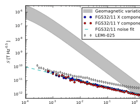
The zero-offset stability and the noise level measurements were conducted in a four-layer magnetic shield. The short-term zero offset drift lies within 40 pT during 7 h. The sen-sor noise level estimations are given in Fig. 2, where for comparison purposes a noise spectral density of the 1 s IN-TERMAGNET magnetometer LEMI-025 and a typical geo-magnetic spectrum are presented. The achieved noise level (≤1 pT Hz−1at 1 Hz) is 3 times less than that of LEMI-025, which could provide better signal-to-noise ratio especially in measurements of short-period geomagnetic variations. The
10-4 10-3 10-2 10-1 100
f [Hz]
10-12 10-11 10-10 10-9 10-8 10-7 10-6
S
[
T
H
z
-0
.5]
Geomagnetic variations FGS32/11 X component FGS32/11 Y component FGS32/11 noise fit LEMI-025
Figure 2.Noise spectra of fluxgate variometers.
zero offset drift, also measured in the magnetic chamber, does not exceed±1 nT during sensor temperature excursions in the range+5 to+35◦C, which is comparable with the best permalloy sensors. Due to the excellent noise level, low short-term zero offset drift and good temperature stability, this sensor is very promising for use in 1 s INTERMAGNET variometers.
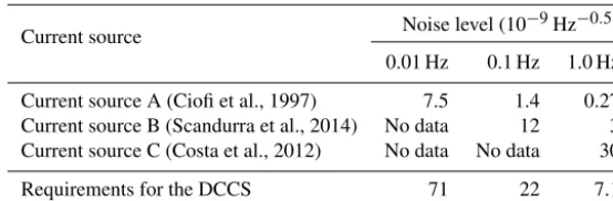
Table 1.Noise level of some digitally controlled current sources.
Current source Noise level (10
−9Hz−0.5)
0.01 Hz 0.1 Hz 1.0 Hz
Current source A (Ciofi et al., 1997) 7.5 1.4 0.27 Current source B (Scandurra et al., 2014) No data 12 3 Current source C (Costa et al., 2012) No data No data 30
Requirements for the DCCS 71 22 7.1
the high-stability compensation field that cancels the main Earth magnetic field inside the magnetic cores. The possibil-ity of constructing a DCCS with temperature and noise char-acteristics consistent with the parameters of the best modern fluxgate sensors is considered in the next section.
3 Development of digitally controlled current source
For the postulated goal achievement, the following noise characteristics of the compensation field were posed: noise level no more than 0.5, 1.5 and 5 pT Hz−0.5 at frequencies of 1, 0.1 and 0.01 Hz, respectively, which constitutes 7.1, 22 and 71×10−9Hz−0.5in relative units taking into account the compensation range of±70 000 nT. Instability of compensa-tion field should not exceed 1 nT or 14 ppm in relative units in the temperature range−40◦C to+60◦C. As the condition of a linear dependence of compensation field on temperature, the thermal drift should be as small as≤0.14 ppm◦C−1. The digitally controlled current source – which consists of a volt-age reference (VR), a digital-to-analog converter (DAC) and voltage-to-current converter – is analyzed.
Analysis of the literature reveals that the problem of cre-ating a stable electric current is associated with relatively high noise level of semiconductor voltage sources. Ciofi et al. (1997) showed that radical reduction of the current source noise can be achieved using a chemical voltage reference; in the paper Scandurra et al. (2014) reference voltage noise reduction was achieved using a low-pass filter that is based on supercapacitors. The current sources’ noise characteris-tics achieved in Ciofi et al. (1997) and Scandurra et al. (2014) meet the requirements for the DCCS (Table 1). Table 1 also shows that the noise of the current source (Costa et al., 2012), which is built using semiconductor voltage reference, ex-ceeds the specified limits several times over. Devices that de-veloped by Ciofi et al. (1997) and Scandurra et al. (2014) are designed to work in the laboratory in a relatively narrow tem-perature range. The stability of these current sources under temperature, time and other factors of influence is not given, but we can assume that, for example, voltage of galvanic ele-ments and supercapacitor parameters could significantly de-pend on the temperature and mechanical stress.
3.1 Voltage reference selection
Based on the detailed review of the characteristics of semi-conductor integrated voltage references (Harrison, 2009), it was found that only very few models have their own noise level, temperature and time drift acceptable to be used in high-class FGMs. The low-frequency (≤1 Hz) noise level characteristics of different voltage reference models are given in Table 2, which is mainly filled with data taken from Fleddermann et al. (2009) and Halloin et al. (2014). Due to a lack of experimental data on the low-frequency noise spec-tral density, we did not include in the table the first buried-Zener voltage reference LM199 designed by Robert Dobkin. This integrated circuit was used by Acuna et al. (1978) in the outstanding MAGSAT magnetometer, the performance characteristics of which are still impressive. An indisputable leader within all specified parameters (that was also designed by Robert Dobkin) is the buried-Zener voltage reference LTZ1000 (Harrison, 2009, p. 494) based on the subsurface Zener diode, whose positive temperature coefficient is com-pensated by the negative coefficient of the forward-biased base-emitter voltage of the transistor located at the same sub-strate. This product of Linear Technology (now part of Ana-log Devices) has also fairly weak dependence of the output voltage on the dose of radiation (Rax et al., 1997), which may be important for space application. Achieving a record-low temperature drift (0.05 ppm◦C−1) is due to controlled heat-ing and maintainheat-ing operation temperature of the chip sub-strate in a very narrow range. Taking into account the signif-icant power consumption, this way is not always acceptable in FGMs and may be unreasonable due to thermal instability of other units of the VR.
−60 −40 −20 0 20 40 60 T[°C]
−200 −150 −100 −50 0 50 100 150
±U
R
E
F
[p
p
m
]
IC~const
IC~PTAT
Ube(VT1)
LTZ1000 no. 1 LTZ1000 no. 2 LTZ1000 no. 3
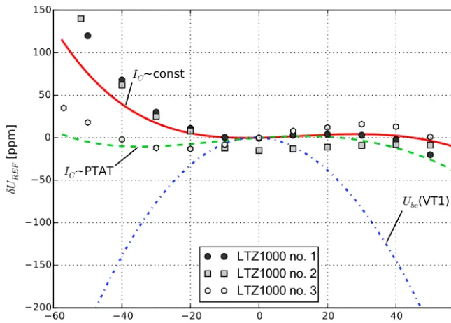
Figure 3.Temperature dependence of LTZ1000 reference voltage – simulated results (lines) and experimental data (marks).
Table 2.Noise level of some precision voltage references.
Voltage reference Noise level (10
−9Hz−0.5)
0.01 Hz 0.1 Hz 1.0 Hz
AD587LN (subsurface Zener) (Fleddermann et al., 2009) 250 70 19 LT1021BCN8-5 (subsurface Zener) (Fleddermann et al., 2009) 700 230 70 LT1236ACN8-5 (subsurface Zener) (Fleddermann et al., 2009) 600 130 35 LTC6655-2.5 (band gap) (Linear Technology Corp., 2014) No data 68 28 LTZ1000 (subsurface Zener) (Linear Technology Corp., 2015) No data 33 9 MAX6126 (proprietary) (Fleddermann et al., 2009) 230 100 50 MAX6250ACSA (subsurface Zener) (Fleddermann et al., 2009) 400 150 40 MAX6350 (subsurface Zener) (Halloin et al., 2014) 1000 600 100 VRE305 (subsurface Zener) (Halloin et al., 2014) 4000 2000 400
of output voltage of LTZ1000 samples. Much better match-ing of the model curve (solid line in Fig. 3) with experiment results was obtained by adding the resistor rb=15 kOhm (Fig. 4) to the LTZ1000 circuit given in the technical doc-umentation (Linear Technology Corp., 2015).
The UREF voltage increase at low temperatures is per-haps due to a decrease of the current transfer coefficient of the transistor VT1 and a corresponding increase in base current and voltage drop at rb, R2 and dynamic resistance of the Zener diode VZ1, since a collector current depends slightly on the temperature (≈0.03 %◦C−1). A possible way to compensate for the effect of the temperature de-pendence of the base current and slightly linearize temper-ature dependence of Ube(VT1) is to generate in the VT1 collector a current IC proportional to absolute temperature (PTAT) of the die. This method is widely used for temper-ature compensation in band gap voltage references
Figure 4.LTZ1000 configuration.
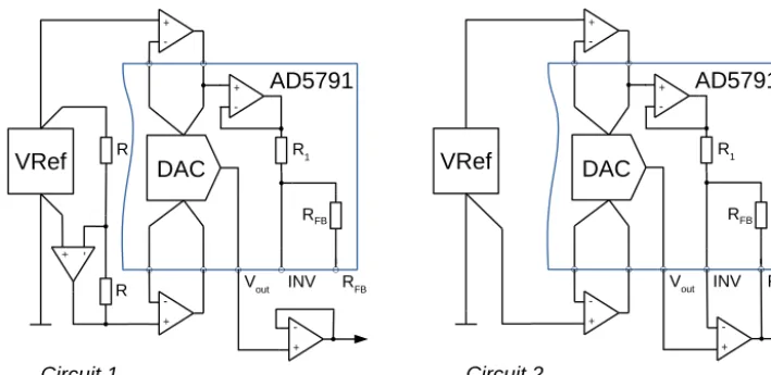
3.2 DAC configuration – bipolar vs. unipolar reference input
As a digital-to-analog converter, one of the best mono-lithic models – a 20 bit DAC AD5791 with temperature drift 0.05 ppm◦C−1 – was selected (Egan, 2010). As the data sheet of this component (Analog Devices, Inc., 2013) con-tains incomplete information regarding the noise level at low frequencies, these characteristics were examined in two cir-cuit configurations: with bipolar (Fig. 6, circir-cuit 1) and unipo-lar (Fig. 6, circuit 2) voltage reference input. The noise tests were carried out using the two samples of the DCCS: sam-ple no. 1 with AD5791 configured for the bipolar reference input and sample no. 2 for unipolar reference input. The voltage references were built using LTZ1000. In the case of the bipolar input DAC configuration (Fig. 6, circuit 1) the negative reference output UREFN was formed from the LTZ1000 positive output voltage UREFP by a voltage in-verter based on a low-noise operational amplifier AD8675 (Analog Devices, Inc., 2012) and a matched pair of the metal foil resistors DSMZ (Vishay Precision Group, Inc., 2015). The noise levels of both unipolar and bipolar volt-age references were estimated before the DAC tests. It was found that the voltage inverter contributed practically no ad-ditional noise, so for both voltage references the noise level mainly depends on the LTZ1000 characteristics and is equal to 9×10⁻⁹Hz−0.5at 1 Hz, 22×10−9Hz−0.5at 0.1 Hz and 70×10−9Hz−0.5at 0.01 Hz. In each case, the DAC output was connected to the voltage-to-current converter with an ungrounded load consisting of a low-noise zero-drift oper-ational amplifier OPA2188 (Texas Instruments Inc., 2016) and high-stability metal foil resistors VSMP0805 (Vishay Precision Group, Inc., 2016). The noise level of these iden-tical voltage-to-current converters was checked separately, and it did not exceed 4×10⁻⁹Hz−0.5in the frequency band 0.01–1 Hz. For each sample, Table 3 shows the noise level
10 20 30 40 50 60 70
T[°C] −20
−15 −10 −5 0 5 10
±U
R
E
F
[
p
p
m
]
IC(VT1)~const
IC(VT1)~PTAT
Figure 5.LTZ1000 voltage curvature correction.
of output currents at the various points in the range: at zero (“Iout=0” column), at the minimum (“Iout=Imin” column) and at the maximum values (“Iout=Imax” column). The val-ues of the noise level which exceed given limits are marked in bold. Overpassing the requirements at a frequency of 1 Hz for both cases is caused by the voltage reference noise. The noise of the AD5791 configured with a unipolar reference input (Fig. 6, circuit 2) is considerably bigger than that of the version with a bipolar reference input and exceeds the re-quirements at zero and minimum values of the output current. Probably, this is due to the additional 1/f noise generated by the resistors R1and RFB(see Fig. 6, circuit 2) when a larger current is flowing through them. At the bipolar input config-uration (Fig. 6, circuit 1) these resistors are excluded from the signal pass and can not contribute an excessive noise. So, for achievement of better noise characteristics, the AD5791 has to be connected in the version of the bipolar voltage ref-erence input.
3.3 The temperature stability of the DCCS
The two prototypes of the DCCS with AD5791 config-ured for a bipolar reference input were intensively tested in order to estimate the temperature dependences of both the separate units and the device in whole. The measure-ments were carried out at the five values of the DAC in-put code: 0x100000 (UDAC=UREFN), 0x13FFFF (UDAC= 0.5UREFN), 0x17FFFF (UDAC=0 V), 0x1BFFFF (UDAC= 0.5UREFP) and 0x1FFFFF (UDAC=UREFP).
Let the DAC output voltage be given by the expression
UDAC=UREFPSDAC+UREFN(1−SDAC), (1)
Figure 6.Digital-to-analog converter configurations.
Table 3.Noise level of the digitally controlled current source.
Frequency (Hz)
Noise level (10−9Hz−0.5)
Requirements
Iout=0 Iout=Imin Iout=Imax
circuit 1 circuit 2 circuit 1 circuit 2 circuit 1 circuit 2
1.0 4 8 9 16 9 9 ≤7.1
0.1 7 14 22 39 22 22 ≤22
0.01 15 42 70 150 70 70 ≤71
causes the relative change of the DAC output voltage as fol-lows:
δUDAC=
1UDAC UREFP
= −(1−SDAC)δSinv. (2) From other side the DAC output voltage could change due to the drift of the reference voltage UREFP and imperfec-tion of the internal components of the AD5791. In order to estimate full-scale and zero-scale error temperature coeffi-cients of the AD5791, we measured simultaneously UREFP, UREFP+UREFN andUDACduring the temperature tests and applied necessary corrections during post-processing. For in-stance, we estimated AD5791 zero-scale error temperature coefficient by measuringUREFP+UREFNandUDAC(0)at the nominal zero DAC output (input code 0x17FFFF, SDAC= 0.5). Then we calculated
δUDAC=1UDAC
UREFP , (3)
δSinv= −
(UREFP+UREFN)
UREFP , (4)
and analyzing the sum(δUDAC(0)+0.5δSinv)we found the zero-scale error temperature coefficient of the AD5791. The results of such measurements for DCCS no. 1 are given in
Fig. 7. The total temperature drift of the DAC output volt-ageδUDAC(0)(markers “♦” in Fig. 7) is mainly caused by instability of the voltage reference inverter (markers “” in Fig. 7), and contribution of the AD5791 zero-scale er-ror temperature drift (markers “
◦
” in Fig. 7) is negligible. For both samples of the DCCS the AD5791 zero-scale er-ror temperature coefficient did not exceed 0.03 ppm◦C−1 in the worst case, which is approximately compatible with data sheet specifications (Analog Devices, Inc., 2013). In both prototypes the drift of the voltage inverters’ scale factors Sinv linearly depends on temperature with coeffi-cients 0.27 ppm◦C−1 in prototype no. 1 and 0.45 ppm◦C−1 in prototype no. 2. These values coincide well with the 0.5 ppm◦C−1maximum-temperature coefficient of the resis-tor ratio (Vishay Precision Group, Inc., 2015). The full-scale temperature coefficients of both AD5791s did not exceed 15 ppm in the temperature range from−40 to+60◦C.−60 −40 −20 0 20 40 60 80
T [°C]
−15 −10 −5 0 5 10 15 20 ±U D A C (0 ) ; ¡ 0 : 5 ±S in v [ p p m ]
±UDAC(0)
¡0:5±Sinv
±UDAC(0) +0:5±Sinv
Figure 7.Temperature drift of the voltage reference inverter scale factor and the DAC zero offset.
markers “
◦
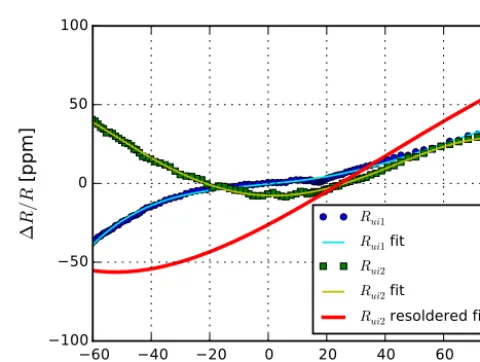
” in Fig. 8 ) does not exceed 5 ppm in the tem-perature range from−60 to+80◦C and is negligible in com-parison with the temperature drift of the transformation fac-tor. Similar results were obtained for the converter in DCCS no. 2, but the transformation factor temperature dependence was much more nonlinear. The temperature tests of the resis-tors, conducted without removing them from the boards, con-firmed thatRui1andRui2depend on temperature in different ways (Fig. 9), and temperature characteristics ofRui2are not compatible with data sheet specifications (Vishay Precision Group, Inc., 2016). Probably, the reason for theRui2 unex-pected temperature dependence was that a mechanical strain occurred when the resistors were soldered on the board. The repeat temperature tests of the same resistors re-soldered in order to minimize possible package deformation reveal con-siderable change of the resistance temperature characteristics (see Fig. 9), which become more uniform and similar to the data sheet curve. In order to avoid the mechanical strain prob-lems, we are going to use through-hole, hermetically sealed versions of the metal foil resistors in future designs.4 Conclusions
The ways to improve noise level and temperature stability of 1 s fluxgate variometers are considered. The noise param-eters of the new fluxgate sensor with Co-based amorphous magnetic alloy are discussed. The achieved sensor noise level is equal to 1 pT Hz−0.5at 1 Hz, which is considerably better than that of the modern observatory fluxgate magnetometers. The short-term zero-offset stability of the sensor is also quite good and lies within 40 pT for 7 h. The zero-offset changes do not exceed ±1 nT during temperature excursions in the range +5 to+35◦C. Besides the sensor performance, it is very important to create the high-stability compensation field
−60 −40 −20 0 20 40 60 80
T [°C]
−40 −20 0 20 40 60 ¢ Su i = Su i [ p p m ]
UDAC=7:2 V
UDAC=3:6 V
UDAC=0 V
UDAC=¡3:6 V
UDAC=¡7:2 V
R¡1
ui1 fit
Figure 8. Temperature drift of the voltage-to-current converter transformation factor.
−60 −40 −20 0 20 40 60 80
T [°C]
−100 −50 0 50 100 ¢ R = R [ p p m ]
Rui1
Rui1 fit
Rui2
Rui2 fit
Rui2 resoldered fit
Figure 9.VSMP0805 resistors temperature dependences.
and the appropriate configuration of its inner structure is se-lected. It is supposed that the application of the results and recommendations discussed in the paper will allow creating an FGM with outstanding level of noise and temperature pa-rameters.
Data availability. The experimental data are not available because they have only intermediate importance and were not registered.
Competing interests. The author declares that he has no conflict of interest.
Special issue statement. This article is part of the special issue “The Earth’s magnetic field: measurements, data, and applications from ground observations (ANGEO/GI inter-journal SI)”. It is a re-sult of the XVIIth IAGA Workshop on Geomagnetic Observatory Instruments, Data Acquisition and Processing, Dourbes, Belgium, 4–10 September 2016.
Acknowledgements. This work was supported by a grant of the National Academy of Science of Ukraine. The author would like to thank the Local Organizing Committee of the XVIIth IAGA Workshop on Geomagnetic Observatory Instruments, Data Acquisition and Processing for financial support.
Edited by: Arnaud Chulliat
Reviewed by: two anonymous referees
References
Acuna, M. H., Scearce, C. S., Seek, J., and Scheifele, J.: The MAGSAT vector magnetometer: A precision fluxgate magne-tometer for the measurement of the geomagnetic field, Techni-cal Memorandum NASA-TM-79656, National Aeronautics and Space Administration, Goddard Space Flight Center, Green-belt, Maryland, available at: https://ia800302.us.archive.org/34/ items/nasa_techdoc_19790010349/19790010349.pdf (last ac-cess: 2 July 2017), 1978.
Afanassiev, Y.: Magnetic Offset and Noise, in: Fluxgate Magne-tometers for Space Research, edited by: Musmann, G., chap. 3, 73–112, 2010.
Analog Devices, Inc.: 36 V Precision, 2.8 nV/√Hz Rail-to-Rail Output Op Amp. Rev. E., available at: http://www.analog.com/ media/en/technical-documentation/data-sheets/AD8675.pdf (last access: 2 July 2017), 2012.
Analog Devices, Inc.: 1 ppm 20-Bit,±1 LSB INL, Voltage Output DAC AD5791. Rev. D., available at: http://www.analog.com/ media/en/technical-documentation/data-sheets/AD5791.pdf (last access: 2 July 2017), 2013.
Auster, H. U., Glassmeier, K. H., Magnes, W., Aydogar, O., Baumjohann, W., Constantinescu, D., Fischer, D., Fornacon, K. H., Georgescu, E., Harvey, P., Hillenmaier, O., Kroth, R., Ludlam, M., Narita, Y., Nakamura, R., Okrafka, K., Plaschke,
F., Richter, I., Schwarzl, H., Stoll, B., Valavanoglou, A., and Wiedemann, M.: The THEMIS fluxgate magnetometer, in: The THEMIS Mission, 235–264, Springer, 2009.
Ciofi, C., Gianatti, R., Dattilo, V., and Neri, B.: Ultra Low Noise Current Sources, in: IEEE Instrumentation and Measurement Technology Conference, Ottawa, Canada, 1997.
Costa, T., Piedade, M. S., and Santos, M.: An ultra-low noise current source for magnetoresistive biosensors biasing, in: 2012 IEEE Biomedical Circuits and Systems Conference (BioCAS), 73–76, https://doi.org/10.1109/BioCAS.2012.6418507, 2012.
Egan, M.: The 20-bit DAC is the easiest part of a 1-ppm-accurate precision voltage source, Analog Di-alogue, 44, available at: http://www.analog.com/ media/en/analog-dialogue/volume-44/number-2/articles/ 20-bit-dac-and-accurate-precision-voltage-source.pdf (last access: 2 July 2017), 2010.
Fleddermann, R., Trobs, M., Steier, F., Heinzel, G., and Danz-mann, K.: Intrinsic Noise and Temperature Coefficients of Se-lected Voltage References, IEEE T. Instrum. Meas., 58, 2002– 2007, https://doi.org/10.1109/TIM.2008.2006133, 2009. Gordon, D., Lundsten, R., Chiarodo, R., and Helms,
H.: A fluxgate sensor of high stability for low field magnetometry, IEEE T. Magn., 4, 397–401, https://doi.org/10.1109/TMAG.1968.1066332, 1968.
Halloin, H., Prat, P., and Brossard, J.: Long term characterisa-tion of electronic components, The 10th Internacharacterisa-tional LISA Symposium, Gainesville, Florida, USA, 18–23 May 2014, available at: http://www.phys.ufl.edu/lisasymposiumx/resources/ contributions/posters/Halloin.pdf (last access: 2 July 2017), 2014.
Harrison, L. T.: Current sources & voltage references, Embedded technology series, Newnes, Amsterdam, digitaler nachdr. edn., 2009.
Ioan, C., Tibu, M., and Chiriac, H.: Magnetic noise measurement for vacquier type fluxgate sensor with double excitation, J. Opto-electron. Adv. M., 6, 705–708, 2004.
Koch, R. H. and Rozen, J. R.: Low-noise flux-gate magnetic-field sensors using ring- and rod-core geometries, Appl. Phys. Lett., 78, 1897–1899, https://doi.org/10.1063/1.1358852, 2001. Koch, R. H., Deak, J. G., and Grinstein, G.:
Funda-mental limits to magnetic-field sensitivity of flux-gate magnetic-field sensors, Appl. Phys. Lett., 75, 3862–3864, https://doi.org/10.1063/1.125481, 1999.
Linear Technology Corp.: LTC6655 0.25 ppm Noise, Low Drift Precision References. Rev. E., available at: http://cds.linear.com/ docs/en/datasheet/6655ff.pdf (Rev. F., last access: 17 August 2017), 2014.
Linear Technology Corp.: LTZ1000/LTZ1000A Ultra Precision Reference. Rev. E., available at: http://cds.linear.com/docs/en/ datasheet/1000afe.pdf (last access: 2 July 2017), 2015.
Merayo, J. M., Brauer, P., and Primdahl, F.: Triaxial fluxgate gra-diometer of high stability and linearity, Sensor. Actuat. A-Phys., 120, 71–77, https://doi.org/10.1016/j.sna.2004.11.014, 2005. Müller, M., Lederer, T., Fornacon, K. H., and Schäfer, R.: Grain
structure, coercivity and high-frequency noise in soft magnetic Fe–81Ni–6Mo alloys, J. Magn. Magn. Mater., 177, 231–232, https://doi.org/10.1016/S0304-8853(97)00672-0, 1998. Narod, B. B., Bennest, J. R., Strom-Olsen, J. O., Nezil, F., and
and B amorphous alloys in ring-core fluxgate magnetometers, Can. J. Phys., 63, 1468–1472, https://doi.org/10.1139/p85-246, 1985.
Nielsen, O. V., Petersen, J. R., Fernandez, A., Hernando, B., Spisak, P., Primdahl, F., and Moser, N.: Analysis of a fluxgate magne-tometer based on metallic glass sensors, Meas. Sci. Technol., 2, 435–440, 1991.
Nielsen, O. V., Petersen, J. R., Primdahl, F., Brauer, P., Hernando, B., Fernandez, A., Merayo, J. M. G., and Ripka, P.: Development, construction and analysis of the ’OErsted’ fluxgate magnetome-ter, Meas. Sci. Technol., 6, 1099–1115, 1995.
Nielsen, O. V., Afanassiev, Y., and Fornaçon, K. H.: Magnetic Ma-terials for Sensors, in: Fluxgate Magnetometers for Space Re-search, edited by: Musmann, G., chap. 6, 152–168, 2010. Nosenko, V. K., Maslov, V. V., Kirilchuk, V. V., and Kochkubey,
A. P.: Some industrial applications of amorphous and nanocrystalline alloys, J. Phys. Conf. Ser., 98, 072016, https://doi.org/10.1088/1742-6596/98/7/072016, 2008.
Paperno, E.: Suppression of magnetic noise in the fundamental-mode orthogonal fluxgate, Sensor. Actuat. A-Phys., 116, 405– 409, https://doi.org/10.1016/j.sna.2004.05.011, 2004.
Rax, B. G., Lee, C. I., and Johnston, A. H.: Degradation of precision reference devices in space environments, IEEE T. Nucl. Sci., 44, 1939–1944, https://doi.org/10.1109/23.658965, 1997.
Sasada, I. and Kashima, H.: Simple design for orthogo-nal fluxgate magnetometer in fundamental mode, Jour-nal of the Magnetics Society of Japan, 33, 43–45, https://doi.org/10.3379/msjmag.0901RF7129, 2009.
Scandurra, G., Cannatà, G., Giusi, G., and Ciofi, C.: Programmable, very low noise current source, Review of Scientific Instruments, 85, 125109, https://doi.org/10.1063/1.4903355, 2014.
Shirae, K.: Noise in amorphous magnetic materials, IEEE T. Magn., 20, 1299–1301, https://doi.org/10.1109/TMAG.1984.1063504, 1984.
Texas Instruments Inc.: OPA2188 0.03-µV/◦C Drift, Low-Noise, Rail-to-Rail Output, 36-V, Zero-Drift Operational Ampli-fiers, available at: http://www.ti.com/lit/ds/symlink/opa2188.pdf, 2016.
Tsividis, Y. P.: Accurate analysis of temperature effects inIC–VBE characteristics with application to bandgap reference sources, Solid-State Circuits, IEEE J. Solid-St. Circ., 15, 1076–1084, https://doi.org/10.1109/JSSC.1980.1051519, 1980.
Turbitt, C., Matzka, J., Rasson, J., St-Louis, B., and Stewart, D.: An instrument performance and data quality standard for in-termagnet one-second data exchange, in: Proceedings of the XVth IAGA Workshop on Geomagnetic Observatory Instru-ments and Data Processing, Cadiz, Spain, 4–14 June 2012, edited by Hejda, P., Chulliat, A., and Catalán, M., 186– 188, available at: http://nora.nerc.ac.uk/507228/1/Turbitt_etal_ IAGAworkshop_OneSecondDataExchange_2013.pdf (last ac-cess: 2 July 2017), 2013.
Vetoshko, P., Valeiko, M., and Nikitin, P.: Epitaxial yttrium iron garnet film as an active medium of an even-harmonic mag-netic field transducer, Sensor. Actuat. A-Phys., 106, 270–273, https://doi.org/10.1016/S0924-4247(03)00182-1, 2003. Vishay Precision Group, Inc.: DSMZ (Z foil). Ultra High Precision
Bulk Metal®Z-Foil Surface Mount Voltage Divider, TCR Track-ing of<0.1 ppm/◦C, PCR of±5 ppm at Rated Power and Sta-bility of±0.005 % (50 ppm), available at: http://www.vishaypg. com/docs/63121/dsmz.pdf (last access: 2 July 2017), 2015. Vishay Precision Group, Inc.: VSMP Series (0603, 0805,