51
Copyright © 2011-15. Vandana Publications. All Rights Reserved.Volume-5, Issue-1, February-2015
International Journal of Engineering and Management Research
Page Number: 51-56
Emerging Trends in Vertical Elevating System
Sudeep Mohaney1, Manish Shah2
1
MTech Scholar, Department of Electrical and Electronics, VITS Indore (M.P.), INDIA
2
Assistant Professor, Department of Electrical and Electronics, VITS Indore (M.P.), INDIA
ABSTRACT
The modern cities have been expanding very rapidly. This expansion seems to be vertical instead horizontal. Vertically expanded city results in high rise building. Traffic handling and energy efficiency are the crucial issues in these buildings. Here the attempt is made to discuses all burning and technical issues of such problem and solution for it.. So there are many new technologies that will bring down all the requirement of vertical transportation. Some of them are describe in this paper.
Keywords — Vertical Elevator system, EGSC and ANN.
I.
INTRODUCTION
In modern development of world time is very valuable. A small saving of time can make a big difference in many ways. So time can be saved in traveling up word or downward in a building. For which elevators are needed. These elevators should be fast and able to carry load of their limit. So an elevator is required which has optimum power consumption and fulfill above requirements. In high rise commercial buildings where height of buildings is increasing vary rapidly then work of elevator also increasing. So fast, energy efficient and economical elevators are required.
Some technologies are developed by some companies which are in use presently. And they are becoming very use full to accomplish the above requirement. These technologies are like TWIN elevator, regenerative drive used by elevator, ultra rope developed for elevator to increase the height of building and some
II.
TWIN ELEVATOR
Twin elevator stands for two cars on a single shaft. The idea of two elevators on a single shaft was originally generated in back 1930s. But because of absence
of modern technologies it is not possible to use this at that time. Now twin elevators are designed by ThyssenKrupp Elevator. It has many advantages for buildings.
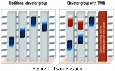
Figure 1 shows the basic of TWIN elevator. This system has many advantages for a building. The main advantage is more space. As shown in above fig in traditional elevator group where 4 shafts are used to run a group of 4 elevators. But twin system achieves the same performance with one shaft less. For new building this means a major gain in usable floor space or a corresponding reduction in building volume. Both cars in a twin system are applied with different counterweight.
Figure 1: Twin Elevator
In modernization projects, a twin system can substantially increase the performance capacity of an existing elevator installation. In a traditional four-shaft group, 40% more passengers can be transported with a twin elevator. Alternatively, one of the shafts can be put to a different use, housing equipment such as air conditioning and cable. Either way, the utility of the building increases significantly.
52
Copyright © 2011-15. Vandana Publications. All Rights Reserved. kind of operation. But for fast and reliable operation ofEGCS some soft computing techniques are required like ANN, PSO and Fuzzy logic. For twin system a touch screen panel is used by passenger to provide the destination of the passenger. Then EGCS will decide the best suitable elevator for the passenger. This process of selecting the next stopping elevator is called destination selection control system for elevator.
There are also some disadvantages of this system which are like a single car one shaft system has to apply with the group of twin elevator system. As twin elevator work but if any passenger is travelling large distance in one direction then he can only use single elevator which is applied on a single and separate elevator. There is another disadvantage of using this system which is safety of system as two cars are travelling on a same shaft then possibility of accident of these two cars is high. Then to eliminate this problem a safety system is employed for this system which will prevent twin cab from getting too close by quadruple redundant safety system. This system monitors the position of elevator and if elevators break the safety distance breached then it will stop the system.
III.
REGENERATIVE DRIVE
Elevator is the best example of all four quadrant operation of electric drive. The four quadrant operations of electric drive are as forward motoring, forward breaking, reverse motoring and reverse breaking.
Figure 2: Four Quadrant operations
Figure 2 shows the operation of elevator in four quadrant of electric drive. If the motoring torque and direction of rotation is same then it is in forward motoring mode. If motoring torque will change in opposite direction then it is in forward breaking mode. Then if direction of rotation and motoring torque both change their direction and applicable in same direction then it is in reverse motoring mode. If from previous mode if direction of torque is change to opposite then this mode is reverse breaking mode.
Figure 3: Regenerative operation of Elevator
When loaded elevator travels in down direction it wants to go faster because of presence of gravitational force. At this time motor act as a generator and generates the power. This power will be used for other works in building. With conventional drives, this energy is converted into heat, which then needs to be removed from the building by air conditioning systems.
The permanent magnet motors in Otis’ ReGen drives are capable of bidirectional energy flow. When power flows into the motor, it creates a lifting torque on the shaft and elevator sheave, lifting the carriage. When the carriage travels down, the motor acts as a generator, transforming mechanical power into electrical power and pumping current back into the facility’s electrical grid to use elsewhere.
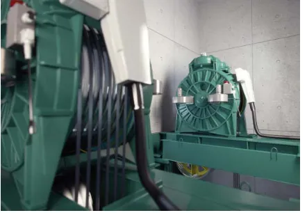
Figure 4: Otis’ ReGen drive courtesy
53
Copyright © 2011-15. Vandana Publications. All Rights Reserved. conventional elevators to fit into the hoist way. Thesespace-saving improvements eliminate the need to build and supply energy to a machine room and consume significantly less energy than the larger versions previously used. They also generate less heat.
Figure 5: Energy Efficient Elevator
A regenerative drive has a substantial impact on an elevator’s energy consumption and is, therefore, a must-have feature when selecting an eco-efficient elevator for a green building. This system has many other advantages like. Regenerative drive can cut elevator energy consumption by 20-35% on average, depending on building height and elevator speed. In certain conditions, for example when there is heavy traffic with full cars, this solution can deliver as much as a 60% reduction in energy consumption. Regenerative solution is highly efficient and eliminates the need to remove heat load created by drive or braking resistors from the building. The regenerative drive produces clean, safe energy.
IV.
ULTRAROPE
Currently, the fastest elevator in the world, made by Toshiba, takes passengers from ground to roof in thirty seconds, rising 33.7 mph through the Taipei 101. This surpasses the speed of the Burj Khalifa’s Otis Elevator, which travels at a mere 22 mph. At 828 meters tall, the Burj Khalifa would still be nearly 300 meters shy (equivalent to the height journey that this new technology proposes.
This advanced vertical transportation will allow building ever-taller skyscrapers to become even more feasible.
Figure 6: KONE ULTRAROPE Elevator Shaft courtesy
developed by KONE, will replace the conventional steel rope used for lifting with one that is developed with a carbon fiber core and a high-friction coating. This rope is extremely light, reducing energy consumption in high-rise buildings as well as reducing the weight of its moving components, such as the hoisting ropes, compensating ropes, counterweight, elevator car, and passenger load. This means, at 800 meters, the weight of the moving masses using KONE Ultra Rope is a fraction of the weight accumulated with the conventional steel rope.
The carbon fiber rope has a number of other advantages. KONE says that since “carbon fiber resonates at a completely different frequency to steel and most other building materials,” elevator downtime caused by building sway will be reduced.
In addition, the rope will have twice the lifetime as steel rope, requiring less maintenance and thereby reduces material waste and environmental impact.
This Ultra Rope increases the weight keeping capacity of elevator. And also helps in increasing the height of commercial building. These ropes are flat in shape which also provides greater strength to carry load in commercial building.
54
Copyright © 2011-15. Vandana Publications. All Rights Reserved. This comes as a breakthrough in elevatortechnology, as Antony Wood, Architect and Executive Director, Council for Tall Buildings and Urban Habitat (CTBUH) states, as one of the major limits of single elevator travel distance was that at a height of approximately 500 meters the weight of the rope became unsupportable. Check out this look at this technology.
V.
ELEVATOR GROUP CONTROL
SYSTEM
Control system is a part of elevator which mainly controls the elevator according to hall call. There is basic principle of elevator working. As elevator moving in one direction it cannot change the direction of movement at time of service. If car came in rest position after the complete service of hall call of same direction elevator can change the direction of movement. This overall process of control an elevator is done by different methods like with the help of microcontroller.
In high rise commercial building traffic of passenger in the elevator is more. Then to control the flow of passenger a group of elevator is used. This group of elevator is controlled by EGCS. This group control uses different technique to control the group of elevator. There is several other work of elevator control system-
1. To bring the lift car to the correct floor. 2. To minimize travelling time.
3. To maximize passenger comfort by providing a smooth ride.
4. To accelerate, decelerate and travel within safe speed limits.
VI.
IMPLEMENTATION USING ANN
ANN is the best soft computing technique for optimization. As TWIN elevator is new technology for high rise building it also require the artificial intelligence for efficient work. ANN will be used as control system for TWIN elevator.
An artificial neural network (ANN) may be defined as an information processing model that is inspired by the way biological nervous system, such as the brain, process information. This model tries to replicate only the most basic function of the brain. The key element of ANN is the novel structure of its information processing system. An ANN is composed of a large number of highly interconnected processing elements (neurons) working in unison to solve the specific problems.
Artificial neural networks, like people, learn by example. An ANN is configured for a specific application, such as pattern recognition or data classification through a learning process. In biological system, learning involves adjustment to the synaptic connections that exist between
the neurons. ANNs undergo a similar change that occurs when the concept on which they are built leaves the academic environment and is thrown into the harsher world of users who simply want to get job done on the computers accurately all the time. Many neural networks now being designed are statistically quite accurate, but they are still leave their bad test as they falter when it comes to solving problem accurately. They might be 85-90% accurate. Unfortunately, few applications tolerate that level of error.
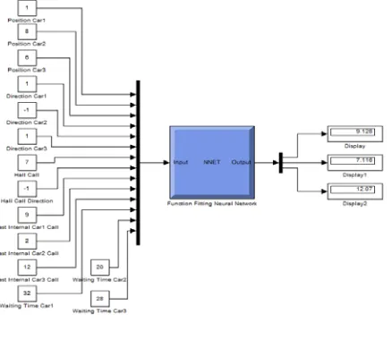
To depict the basic operation of a neural net, consider a set of neurons; say X1, X2, X3…. Xn. Transmitting signal to another neuron, Y. Here X1 and X2 are input neurons, which transmit signal, and Y is the output neuron, which receive signal. Input neurons connected to the output neurons via weighted interconnection links (W1 and W2) as shown in figure 8.
Figure 8: Mathematical model of artificial neuron
………….…… (1) Variable of ANN
1. Position
This parameter tells about the current position of the car. Car may be stationary or moving but at the time of hall call the position of car is important. For three elevators three positions are taken as input.
2. Direction
Travelling direction of car is also important as input for ANN. Direction of car is only can be up or down. For preparation of data set “1” is taken as up direction and “-1” is taken as down movement of car.
3. Hall Call
Hall call is the position where passenger stands and wants the elevator on this floor. It can be 1 to 15 any floor.
4. Hall Call Direction
When any passenger demands any elevator he also decides the direction which he wants to travel. Up and down notation is same as direction of elevator. “1” is for up, “-1” is for down.
55
Copyright © 2011-15. Vandana Publications. All Rights Reserved. Last internal hall call shows the final destinationof travelling passenger. As 2 or 3 passengers travelling in the elevator then there will be 2 or 3 internal hall call. Then last internal hall call is decided according to the passenger who is traveling largest distance.
6. Number of stops in between position and hall call To calculate waiting time of elevator it is important to calculate number of stops. If hall call comes first than last internal hall call then the stops will be calculated in between position and hall call. And if last internal hall call comes first than hall then the stops will be calculated in between position and last internal hall call. For every stop we are assuming that elevator takes 6 sec to move again.
7. Number of floor between position and hall call Again for calculation of waiting time number of floors is required. For every crossing of floor, elevator speed is considered as 2 m/s then it takes 2 sec to cross a floor if height is taken as 4 m of every floor.
8. Waiting Time
Waiting time is calculated with the help of number of stops and number of floors. In ANN waiting time is calculated with the help of given equation.
……..….. (2) After the calculation of all the input parameter one output parameter is also calculated this will work as target for ANN.
The output parameter is: 1. Output
On basis of waiting time output is calculated. One elevator will have least waiting time then this will be assign to serve the hall call and remaining to will serve their respective last internal hall call.
Figure 9: Simulink Model of ANN
VII. RESULT
The main result is when hall call is from 7th floor, because of least waiting time car2 will serve the hall call
and remaining cars will serve their respective last internal car calls.
TABLE 1
Result of Target Output and Error of ANN
Target Output Error=Output-Target
9 9.128 0.128
7 7.118 0.118
12 12.07 0.07
From the result it is clear that ANN will provide next stopping floor for the elevator. In TWIN elevator technology this system is used to find the next stopping floor for the elevator.
VIII. CONCLUSION
TWIN elevator is the very new technology for high rise commercial building to get higher and higher buildings. In the high rise commercial building where time is very important then this technology is very use full. Other technology is ReGen tech from OTIS, which is based on regeneration technology which will save considerable amount of energy in the working of elevator. KONE also provide tech like UltraRope which is help full in the increment height of buildings. But for fastest, economic and efficient work a batter control system is required. ANN will full fill this requirement the above result shows the working of ANN in EGCS.
REFERENCES
[1] George R. Strakosch and Robert S. Caporale “The Vertical transportation handbook”, Wiley India Pvt. Ltd. [2] Gina Carol Barney “Elevator Traffic Handbook Theory and Practice”, Spon press London, 2003.
[3] S. N. Sivanandam and S. N. Deepa “Principles of Soft Computing”, Wiley India Pvt. Ltd. New Delhi.
[4] Bimal K. Bose “Power Electronics and AC Drives”, Prentice Hall PTR 2002.
[5] Charles A. Gross “Electric machine”, CRC Press Taylor & Francis Group.
[6] Duane Hanelman & Bruce Little Field “Mastering MATLAB 7”, Pearson Education in South Asia.
[7] Amos Gilat “MATLAB an Introduction with Application”, Wiley India Pvt. Ltd. New Delhi.
56
Copyright © 2011-15. Vandana Publications. All Rights Reserved. IEEE International Conference on Control and AutomationGuangzhou, CHINA - May 30 to June 1, 2007.
[9] Yine Zhang, Yun Yi and Jian Zhong “The Application of the Fuzzy Neural Network Control in Elevator Intelligent Scheduling Simulation”, Third International Symposium on Information Science and Engineering 2010 IEEE.
[10] Jianzhe Tai, Suying Yang and Hong Tan “Dispatching Approach Optimization of Elevator Group Control System with Destination Floor Guidance using Fuzzy Neural Network”, proceedings of the 7th World Congress on Intelligent Control and Automation June 25 - 27, 2008, Chongqing, China 2008 IEEE.
[11] Cao Liting Zhang Zhaoli and Hou Jue “Dynamic Optimized Dispatching System for Elevator Group Based on Artificial Intelligent Theory”, The Eighth International Conference on Electronic Measurement and Instruments 2007 IEEE.
[12] Zhi-Ming Chen, Fei Luo, Yu-Ge Xu and Jian-Zhong Cao “Design and Implementation of Modern Elevator Group Control System”, Proceedings of the Fifth International Conference on Machine Learning and Cybernetics, Dalian, 13-16 August 2006 IEEE.
[13] Zhenshan. Yang, Cheng. Shao, and Guizhi. Li. “Multi-Objective Optimization for EGCS Using Improved PSO Algorithm”, Proceedings of the 2007 American Control Conference Marriott Marquis Hotel at Times Square New York City, USA, July 11-13, 2007 IEEE. [14] J. Fernández, P. Cortés, Member, IEEE, J. Muñuzuri, and J. Guadix “Dynamic Fuzzy Logic Elevator Group Control System with Relative Waiting Time Consideration”, IEEE Transactions on Industrial Electronics, Vol. 61, No. 9, September 2014.
[15] Yanwu Gu “Objective Optimization of Multi-Agent Elevator Group Control System Based on Real-Time Particle Swarm Optimization Algorithm”, Scientific Research Engineering, 2012, 4, 368-378.
[16] C. Erdem Imrak “Artifical Neural Network Application in Duplex/Triplex Elevator Group Control System”, Strojniski vestnik – Journal of Mechanical Engineering 54(2008)2, 103 – 114.