744
Copyright © 2011-15. Vandana Publications. All Rights Reserved.
Volume-5, Issue-3, June-2015
International Journal of Engineering and Management Research
Page Number: 744-755
Under Floor Air Distribution for Better Indoor Air Quality
Shaik Gulam Abul Hasan1, Shaik Mohd Amoodi2, Ganoju Sravan Kumar3 1,2
Assistant Professor, Mehanical Department, Vidya Jyothi Institute of Technology, C.B. Post, Aziz Nagar, INDIA 3
Assistant Professor, Mehanical Department, MGIT, C.B. Post, Aziz Nagar, INDIA
ABSTRACT
UAD systems are shown to offer potential for initial capital savings, which may be achieved by lowering slab-to-slab heights, reducing cooling capacity requirements due to stratification, thermal inertia improvements, minimizing ducting, and reducing construction schedules.UAD systems are also shown to provide significant energy efficiency advantages due to fan energy savings, extended free cooling and improved chiller COP, thereby reducing life-cycle building costs. Additionally, improvements in occupant thermal comfort and Indoor Air Quality (IAQ) are achieved. Unlike displacement systems, UAD systems extend these high levels of IAQ to applications with significant movement and/or heating.
In typical office environments, UAD systems are also able to provide more than three-to-five times the maximum sensible cooling capacity of comparable displacement systems without subjecting occupants to draughts or to an excessive vertical temperature gradient. They also improve air flow in the occupancy microclimate and provide the opportunity for localized control of air flow and direction, further enhancing individual thermal comfort. These advantages raise worker productivity and lower absenteeism rates. The ease with which UAD systems can be rearranged to satisfy new office layouts improves flexibility, reducing reconfiguration costs.
Keywords---- UAD systems, Indoor Air Quality (IAQ), air flow
I.
INTRODUCTION
1.1 Refrigeration:
The term refrigeration refers to cooling an area or substance below the environmental temperature, the process of removing heat. Mechanical refrigeration uses the evaporation of a liquid refrigerant to absorb heat. The refrigerant goes through a cycle so that it can be reused,
the main cycles are; vapour-compression, absorption, steam-jet or steam-ejector, and air.
1.2 Applications of refrigeration:
In commerce and manufacturing, there are many uses for refrigeration. Refrigeration is used to liquify gases compressed air purification, it is used to vapor from compressed air to reduce its moisture content. In refrigeration is used to maintain certain processes at their needed low temperatures (for example, in high refrigeration to temper steel and cutlery. In transporting temperature-sensitive foodstuffs and other materials by trucks, trains, airplanes and sea-going vessels, refrigeration is a necessity.
1.3 Air-Conditioning
:
Air-conditioning is a process that simultaneously conditions air; distributes it combined with the outdoor air to the conditioned space; and at the same time controls and maintains the required space’s temperature, humidity, air movement, air cleanliness, sound level, and pressure differential within predetermined limits for the health and comfort of the occupants, for product processing, or both. The acronym HVAC&R stands for heating, ventilating, air-conditioning, and refrigerating. The combination of these processes is equivalent to the functions performed by air-conditioning.
Air conditioning makes 1.4 Air-conditioning applications:
745
Copyright © 2011-15. Vandana Publications. All Rights Reserved.
applications are quite different for various building types and may be categorized as
• Low-Rise Residential buildings, including single
family houses, duplexes, and small apartment buildings
• High-Rise Residential buildings, such as tall
dormitories and apartment blocks
• Commercial buildings, which are built for
commerce, including offices, malls, shopping centers, restaurants, etc.Institutional buildings, which includes government buildings, hospitals, schools.
1.5 The Importance of Air Conditioning and Refrigeration:
The most common, and arguably most important, use for refrigeration is food preservation. It used to be that people had to go to a market every day and buy fresh groceries before they perished. Early methods of food preservation such as cold cellars and salting were expensive, difficult to regulate, and didn’t maintain the same quality as what we are used to today. After the discovery of bacteria the importance of refrigeration became clear. Low temperatures slow chemical and biological processes including bacterial growth which spoils food. Modern refrigeration provides an environment too cold for harmful bacteria to flourish, keeping people healthy.With contemporary refrigeration units I can buy lunch meat on Sunday and have it last all week long. A reliable method for keeping foods cold means I have to shop less frequently. It also allows for foods to be frozen and eaten out of season. Even if I ran out of my frozen fruits and vegetables, I could also buy out-of-season edibles from a place where they are in-season. Foods can be refrigerated and transported across the country and across the world. This means that I can now have a more diverse diet than what is grown in my area. Current refrigeration technology has changed our diets and lifestyles to be more diverse and healthy.
2.Under Floor Air Distribution (UFAD):
Under floor air distribution systems have been utilized since the 1950’s to serve spaces having high heat loads, such as computer rooms and control centers, but they are still relatively uncommon in an office environment. Most buildings are designed using a conventional overhead distribution system, which generally supplies cold conditioned air (typically 550
Cool conditioned air – typically between 63F and 68F – is supplied at floor level through diffusers at very low velocity. The air is then heated by the internal loads of the space and rises to the ceiling where it returns back to the central air handling unit. Potential advantages of an under floor air distribution system compared to a traditional ceiling-based system include improved thermal comfort, improved air quality, and reduced energy consumption (CBE 2002). All of this sounds rather simple, but many design issues can greatly influence system performance and success of the application, for example: the type of plenum used – pressurized or non-pressurized, open or partitioned; how interior and perimeter loads are to be met; how humidity will be controlled; and diffuser selection – passive or active. Once the design is complete, the entire system must be constructed, commissioned, and then maintained to ensure that present and future system operation and occupant comfort are sustained.A Maintaining a high level of indoor air quality (IAQ) become increasingly important to today’s business owners and their employees, engineers are challenge to improve HVAC Design. Design to provide comfort and better Indoor Air Quality with traditional air distribution system consumes high amounts of energy and there for, results in high operational cost the challenge HVAC engineers face is to provide comfort while reducing energy consumption and the operating expenses that company it. In response to new regulation and rising energy costs, the HVAC industry is changes at a rapid pace, providing today’s engineers with new tools to meet this challenge.
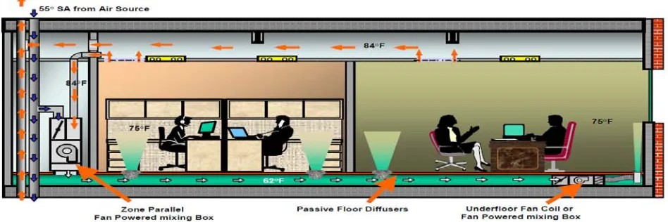
Under floor aid distribution (UAD) turns air supply upside down, allowing a floor plenum to deliver conditioned air to the space via floor grilles in the raised floor system. The floor plenum typically consists of pedestals and removable floor panels that can be rapidly reconfigured. Supply air is introduced through diffusers at floor level and is exhausted at the ceiling through return or relief grilles.Under floor air distribution systems introduce air at the floor level, with return grilles located near the ceiling. The space is divided into two zones, an occupied zone extending from the floor to head level, and an unoccupied zone extending from the top of the occupied zone to the ceiling. The systems are designed to condition the lower occupied zone only temperature conditions in the upper zone are allowed to float above normal comfort ranges. To avoid occupant discomfort, air is introduced into the space between 65°F and 68°F. In contrast, traditional overhead ventilation systems supply and return air at the ceiling. The system produces a large single zone of fully-mixed, room-temperature air. Using a liquid and
beaker analogy, Figure 1 & Figure 2 is a simplified
illustration of the difference between an under floor system and a conventional fully-mixed system.
F) at the ceiling and relies on complete mixing from floor to ceiling to maintain space temperature. In order to achieve complete mixing, the conditioned air must be delivered through the diffusers at relatively high velocity. The concept behind an under floor air distribution system is to create a stratified condition from floor to ceiling, rather than mixed, and rely on the natural buoyancy of the air to remove heat and contaminants away from the occupants.
746
Copyright © 2011-15. Vandana Publications. All Rights Reserved.
unoccupied zone above. In the fully-mixed system, cooler liquid delivered from above mixes with all the liquid to maintain a constant temperature throughout the beaker. This dilutes contaminants but does not effectively purge them. The figure 1 shows a beaker filled and emptied from the top, much like an overhead mixed ventilation system.
The figure shows a beaker filled with cool water from the bottom, with warm water exiting from the top.
III.
ROOM AIR DISTRIBUTION
Characterizing how air is introduced to, flows through, and is removed from spaces is called room air distribution. Air distribution systems fall into three general categories distinguishable from one another by the temperature and velocity profiles they create in the occupied space.
1. Mixing (or dilution)
2. Displacement.
3. Hybrid under floor system.
IV.
DESIGN AND CALCULATIONS OF
UNDER FLOOR AIR DISTRIBUTION
4.1 Plenum Design:
The raised floor office can be supplied with conditioned air from below the floor in two ways pressurized plenum or neutral plenum.
4.1.1 Pressurized Plenums:
The pressurized plenum (the area between the slab and the raised floor) is essentially a large duct maintained at a constant pressure differential to the room above; typically between 0.05 and 0.10 in. pressure (w.g.). This pressure is maintained through the supply of conditioned air from a number of supply duct terminations.
The spacing and location of these ducts are dependent on the air supply requirement and the plenum depth, with shallow plenums and / or high air quantities requiring more air supply duct outlets under the floor. UFAD diffusers are specially designed grilles with a user adjustable damper to regulate flow. Sealing the under floor plenum is critical to optimizing the operation of a UFAD system. Air leaking through the floor tiles into the occupied zone is of minimal concern because it is leaking into the occupied space. Air leaking into the space between the walls, however, is wasted energy. All knockouts and holes in the drywall below the raised floor must be sealed during construction.
The advantages of pressurized plenums include low first cost and easily changed layouts. This is the most commonly used plenum design.
4.1.2 Neutral Plenums:
With the neutral plenum design, the same layout as the pressurized plenum may be used, but the pressure difference between the plenum and the room is kept as close as possible to zero. Floor diffusers either contain integral fans, are ducted from a central source, or both. In many cases, these closely resemble conventional ceiling supply systems.Advantages include the possibility of multiple small zones (as with multiple tenants) and insensitivity to construction details. Disadvantages include higher first costs due to ducting and/or fan connections under the floor, lower flexibility as the grilles are individually ducted, and potentially higher noise levels.This design is rarely used, but may be effective in tenant buildings where the utilities will be paid by the tenant.
4.2 Plenum Details:
Plenum heights typically range from 14” to 18”, occasionally going as low as 12”. The plenum height is usually determined by the height requirements of other equipment that will be located under the floor. The number of inlets required to supply the plenum with sufficient air to run the diffusers is dependent upon the plenum size and the number of diffusers, which in turn is determined by the load of the space.
As a general rule, the longest distance from the supply air outlet in the plenum and the farthest diffuser should not exceed 50-65 feet. Distances longer then this are subject to thermal losses and the discharge temperature of the diffuser may be too high.
747
Copyright © 2011-15. Vandana Publications. All Rights Reserved.
plenum to run a separate perimeter system. Typically only the perimeter is zoned from the core.
4.3 Perimeter Systems:
The perimeter is typically the most difficult area of an under floor system to design. The perimeter is often handling much larger loads and require the most equipment. In the past, the best way to handle the perimeter was to use fan powered terminals with reheat ducted to linear bar grilles. There are a couple challenges with this design concept. The throw of a linear bar grille ducted to the discharge of a fan powered terminal is very long, possible as long as 15-20 feet. Designing long throws
at the perimeter contradicts the concept of stratification in a UFAD system. Not only does the long throw from the grille mix the air above the stratified layer into the occupied zone, wasting energy, but it also may roll up the glass and across the ceiling, where it drop into the occupied zone causing discomfort for the occupants. Although the concept of UFAD systems is to be modular, the function of handling perimeter loads is not modular. Those loads come with the building envelope, which is always a line of some sort. The TAF-L Perimeter System was designed to address all of these considerations.
Fig no: 4.1 Typical under floor Plenum Configuration
4.4 Conference Rooms & Other Areas of Varying Load:
Much like the perimeter, conference rooms must be handled separately to adjust for the varying load conditions. The LHK fan powered terminal was designed for this application. Like the PFC, the LHK fits within the modular pedestal systems of the raised floor and is available in various heights to fit under 12” through 18” raised floors. With the exception of its unique dimensions, the LHK is like any other series fan powered terminal. The LHK has a supply inlet with a damper modulated by a controller and actuator. The LHK has an induced air inlet which pulls air from the under floor plenum or from the room depending on how the LHK is applied.
The LHK supply inlet would be open to the plenum with the induced air inlet ducted to the room as the return. The discharge would then be flex ducted to TAF-R’s in the room.
4.5 Return Air:
Due to the upward air flow, returns should be located at the ceiling or on a high side wall. This allows
the heat from ceiling lights to be returned before it is able to mix with the conditioned air in the occupied zone. There will also be a small amount of “free cooling” due to the natural buoyancy of hot air. If the system must use 55oF supply air for humidity reasons, some of the return air can be recirculated from the ceiling to the under floor plenum to raise the temperature of the air to 63oF to 68oF.
Another option is to take the return air back to the air handling unit where it can be filtered and dehumidified before re-entering the under floor plenum. With this option, you can more accurately control the air temperature at the diffuser and you gain the cost benefits of the warmer supply air temperature.
4.6 Humidity Issues:
748
Copyright © 2011-15. Vandana Publications. All Rights Reserved.
55oF dew point condition.System designs utilizing condenser water reheat, run-around coils, face & bypass, and other strategies can be employed to solve these potential design problems. Other possible solutions include the use of a separate system to dry outside air or the use of
desiccant dehumidification. Climate and building
operation are important considerations when designing a UFAD system. In humid climates, it may be necessary to operate the HVAC system 24 hours a day to maintain acceptable humidity levels in the building.
4.7 Sizing Jobs:
The optimum design point for the TAF-R is 80 - 100 CFM when a 10oF room / supply differential is used. At this point, the noise is negligible and the pressure required is less than 0.10”. Throw will be less than 6 ft., preserving the desired ceiling stratification layer. Our
testing shows that there is 100% mixing in the occupied zone under these conditions.
The stratification in this installation results in a supply - exhaust ΔT similar to the typical 18oF to 20o
For example, with 64
F ΔT
common in most conventional systems. o
F supply air in a 74oF room, the room exhaust, at the ceiling, will probably be about 82oF, for an 18o
This means that one diffuser can handle:
F ΔT.
18o
Lights are typically 0.75 W/sq.ft, but with ceiling stratification are probably not a part of the room load (but are seen by the air handler). If computers and printers supply about 1W/sq.ft load and occupants add about 1.2 W/sq.ft, this translates to:
F ΔT x 100 CFM x 1.08 = 1944 BTUH or 1944 BTUH
÷ 3.41 = 570 watts of internal load.
4.8 Design Guide To Under Floor Air Distribution: 4.8.1 Design Decisions:
When beginning the design of a UFAD system certain key differences and concepts need to be remembered to avoid incorporating elements of traditional overhead mixing systems:
Under floor systems work best when a
stratification layer is established at 6 feet above the access floor. This creates a partial displacement ventilation effect within the room and improves ventilation effectiveness, contaminant control, heat capture, and reduces loads within the space, transferring them directly to the return air.
Airflows need to be closely matched to the loads
within the occupied zone so as not to over air the space, losing the partial displacement ventilation effect.
Mixing only occurs within the occupied zone and
happens so efficiently that it is normal for a 3 to 5º F temperature gradient to occur, right at the ASHRAE 55 comfort standard limit.
Do not include excess safety factors; it will lead
to over airing the zone spaces, resulting in many occupant comfort complaints and loss of the stratification layer.
4.8.2 Zoning Decisions:
Because of the under floor air supply plenum aspects of a UFAD system, zoning decisions have a few complexities:
Thermal decay, the increase in cooling supply air
temperature due to heat transfer to the floor slab and access flooring, limits the zone maximum travel distance from the terminal discharge into the plenum to the furthest diffuser to 50-60 feet. So for a typical side-fed core location the maximum zone size would be 120 ft by 60 ft, or 7200 ft2 or less.
Open office interior zones, those that have fairly
uniform loading, lend themselves to pressurized plenums using passive swirl diffusers.
Zones with high heating loads need to consider
749
Copyright © 2011-15. Vandana Publications. All Rights Reserved.
thermal decay. Insulate ductwork to prevent loss of cooling capacity.
Perimeter zone size may be restricted by
ASHRAE 90.1, requirements for exposure zoning, which limits linear wall per exposure to 50 feet.
Locating zone-mixing terminals in vertical
equipment closets does take up more useable floor space compared to locating the units within the underfloor plenum, but is a good choice for reasons of ease of maintenance and minimizing obstructions within the plenum.
When high cooling or dehumidification loads are
present, such as conference rooms and rooms with plants, process or large equipment or solar loads, consider conditioning these spaces with traditional VAV terminals using lower temperature (50 to 55ºF) primary air. This hybrid system design will result in smaller central equipment, as well as ductwork mains and branches
4.9 General Layout:
When beginning the layout of a UFAD system it is best to think of it as an upside down conventional
overhead system, with the following similarities and differences:
Central cooling and heating equipment, as well as
ductwork mains and branches to zone mixing terminals, can be nearly identical to traditional overhead systems. s. Systems that do not employ the use of zone mixing terminals require special consideration based on the volume and temperature from the air-handling source.
When using zone fan powered mixing boxes
(FPMB) above the access floor the chases must provide adequate room to locate the terminal as well as provide required service clearances.
UFAD systems use diffusers in the access floor,
much closer to the occupants, so special care needs to be exercised in their layout. Since it is a non-ducted system, simply swapping floor panels can make relocations easy.
UFAD systems work best with uniformly loaded
thermal areas. In high-load and variable-loaded zones, UFAD can be used in conjunction with traditional overhead systems. This creates an overall hybrid system that utilizes the best features of both types of systems (figure 10b).
Fig no. 4.2 UFAD with Zone Mixing System
4.15.1 About This Document:
These user notes describe how to use the spreadsheet-based (Excel 2007) version of the UFAD design tool for calculating the design cooling load and zone design cooling airflow required for an Under floor Air Distribution (UFAD) system.
4.15.2 Overview of the UFAD Cooling Load Design Tool Spreadsheet:
The design tool is composed of eight worksheets but just the "Model" and "Comparison" should be used. The other worksheets are for calculation purposes and should be accessed only by expert users. The “Calculation2”, “Calculation4”, “Calculation6”, "Working
Data", "Non Dimensional Temp" and "Diffuser Type" worksheets should not be modified; they cannot be hidden due to VBA limitations. Only IP (Inch-Pound) units can be used.
750
Copyright © 2011-15. Vandana Publications. All Rights Reserved.
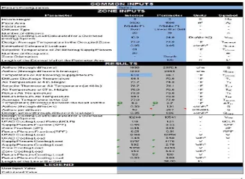
Most of the inputs that characterize the building are inserted in the “Zone Inputs” section. The results are displayed in a tabular form in the "Results" section and some of the most important results are displayed in the five graphs reported next to the table. On the right-hand side of the page, there are three groups of figures. In the first are shown the temperature stratification profiles and the plenum temperatures of the interior and perimeter zones. Below this first group are cooling load charts, for interior and perimeter zones.
These charts show the loads for the UFAD system being analyzed and for an equivalent overhead system subject to the same heat gains (and from which the UFAD loads have been derived). For the UFAD system the figure shows how the cooling load is divided between the cooling load in the supply plenum, the zone (room) and the return plenum. On the far right side, there is a histogram of the design cooling airflow rates for both the interior and
perimeter zones. A detailed description of the inputs and
outputs are listed below under "Input and Output Descriptions."
751
Copyright © 2011-15. Vandana Publications. All Rights Reserved.
Fig no. 4.6 UFAD cooling load design tool spread sheets.
4.15.3 Input And Output Descriptions:
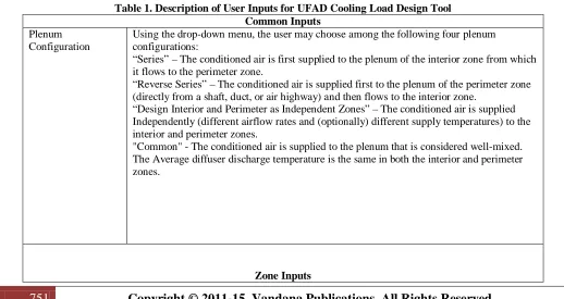
Table 1 lists and describes the user input data in the order of appearance in the worksheet. The output data are listed and described in Table 2.
Table 1. Description of User Inputs for UFAD Cooling Load Design Tool Common Inputs
Plenum Configuration
Using the drop-down menu, the user may choose among the following four plenum configurations:
“Series” – The conditioned air is first supplied to the plenum of the interior zone from which it flows to the perimeter zone.
“Reverse Series” – The conditioned air is supplied first to the plenum of the perimeter zone (directly from a shaft, duct, or air highway) and then flows to the interior zone.
“Design Interior and Perimeter as Independent Zones” – The conditioned air is supplied Independently (different airflow rates and (optionally) different supply temperatures) to the interior and perimeter zones.
"Common" - The conditioned air is supplied to the plenum that is considered well-mixed. The Average diffuser discharge temperature is the same in both the interior and perimeter zones.
752
Copyright © 2011-15. Vandana Publications. All Rights Reserved.
Parameter Zone Unit Sym Description
Room Height I-P ft H Height between the raised floor and the suspended
ceiling. ft
Floor Area I-P ft2 A f Floor area of the zone analyzed.
Floor Level I-P - - Using the drop-down menu, the user may choose among
the following three floor levels:
“Ground Fl.” – The floor slab is in contact with the ground.
“Middle Fl.” – The floor is between other floors. “Top Floor” – The floor under the roof.
Diffuser Type I - - Using the drop-down menu, the user may choose among
the following
two diffuser types for interior zones: “Swirl” – ‘Standard’ swirl diffusers
“VAV Directional I.” – Diffusers that automatically vary the air flow rate and keep the throw height constant
Diffuser Type P - - Using the drop-down menu, the user may choose among
the following
two diffuser types for perimeter zones:
“Linear Bar Grille” – Linear bar grille diffusers are used. When this option is chosen the software will ask the user to enter the length of the bar grille. The default value is 18 in.
“VAV Directional P.” – Diffusers that automatically vary the air flow rate and keep the throw height constant
Number of diffusers I-P - n Using the drop-down menu, the user may choose among
the following
Two diffuser types for perimeter zones:
“Linear Bar Grille” – Linear bar grille diffusers are used. When this option is chosen the software will ask the user to enter the length of the bar grille. The default value is 18 in.
“VAV Directional P.” – Diffusers that automatically vary the air flow rate and keep the throw height constant Design Cooling
Load Calculated for an Overhead (mixing)
System
I-P kBtu/hr
or Btu/(hr
ft2
W
)
Design cooling load calculated using traditional cooling load software (e.g. ASHRAE RTS method, etc.). This cooling load is the sum of the zone and the return plenum cooling load. The design cooling load for the analyzed zone should be calculated using the assumption of well mixed air. The overhead cooling load should be calculated for the same set point temperature used for the UFAD system ("Design Average Temperature in the Occupied Zone - Toz,avg,d).The user has the option to input the cooling load in kBtu/hr or Btu/(hr ft2) by using the drop-down menu in the "Units" column.
OH
Design Average Temperature in the
Occupied Zone
I-P 0F T Room (or zone) design air temperature set point. In an
overhead system this is the thermostat temperature set point. For a stratified environment,
it is the average occupied zone temperature. oz,avg,d
Estimated Category 2
Leakage
I-P cfm/ ft2 q Category 2 leakage is defined as uncontrolled air leakage
753
Copyright © 2011-15. Vandana Publications. All Rights Reserved.
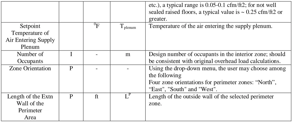
etc.), a typical range is 0.05-0.1 cfm/ft2; for not well sealed raised floors, a typical value is ~ 0.25 cfm/ft2 or greater.
Setpoint Temperature of Air Entering Supply
Plenum
0
T
F plenum Temperature of the air entering the supply plenum.
Number of Occupants
I - m Design number of occupants in the interior zone; should
be consistent with original overhead load calculations.
Zone Orientation P - - Using the drop-down menu, the user may choose among
the following
Four zone orientations for perimeter zones: “North”, “East", "South" and "West".
Length of the Extn Wall of the
Perimeter Area
P ft L Length of the outside wall of the selected perimeter
zone. P
Zone. I-P = the description is applicable to both interior and perimeter zones; I = the description is applicable only to interior zone; P = the description is applicable only to perimeter zones.
Table 2. Description of Output Data for UFAD Cooling Load Design Tool Results
Parameter Zone Unit Sym Description Airflow (through
diffusers)
I -P cfm Q Total room airflow rate delivered by the diffusers only in
the studied zone Design airflow (through
diffusers & leakage)
I -P cfm Q Total (combined) room airflow rate; sum of airflow rate
through the diffusers (Q) and Category 2 leakage. Room
Temperature of Air Entering Supply Plenum
I –P °F TRlenu Temperature of the air entering the supply plenum
m Diffuser Discharg
Temperature
I –P °F T Temperature of the air entering the room from the diffusers.
This temperature is equal to the average temperature of the plenum.
s
Air Temperature at 4 in.Height
I –P °F T4 Air temperature at 4 in. (ankle height).
Set point Air Temperature (at 48 in.)
I –P °F T Thermostat setpoint temperature. This temperature is
different from the average temperature in the occupied zone. This is the temperature that has to be set at the thermostat to obtain Toz,avg in a thermally stratifiedenvironment.
set
Air Temperature at 67 in.Height
I –P °F T67 Air temperature at 67 in. (head height for a standing person)
Return Air Temperature I –P °F T Temperature exiting the room at ceiling height and entering
the return plenum. R
Return Plenum Air Temperature
I –P °F T Temp. exiting the zone return plenum. This is not the air
temperature going to the AHU. The return plenum air temperatures for the different zones on a given floor have to be properly weighted to calculate the average air temperature returning to the AHU from that floor. This calculation is not performed in the design tool.
RP
Average Temperature in the Occupied Zone
I –P °F T Average temperature in the occupied zone. The design tool
754
Copyright © 2011-15. Vandana Publications. All Rights Reserved.
temperature at the thermostat height of 48 in. (1.2 m). Temperature difference
between the head and the ankle (from 67 in. to 4in.)
I –P °F ΔT Air temperature difference between head (67 in.) and ankle
(4 in.) heights of a standing occupant. According to ASHRAE 55-2004, the maximum allowable temperature difference between head and ankle is 5.4°F (3°C).If the temperature difference is higher that 5.4°F a red circle appears next to the number, if it is lower than 5.4°F a green circle appears, and if it is equal a yellow circle appears. oz
Airflow (through diffusers I –P cfm/ ft2 Q Airflow rate through the diffusers expressed in cfm/ft2
Airflow per diffuser I –P cfm/
diff
Q Airflow rate per diffuser. In the design condition this value
should be equal to or less than the value recommended by the diffuser vendor.
Design airflow (through diffusers & leakage)
I –P cfm/ ft2 Q Total (combined) room airflow rate (Qroom) expressed in
cfm/ft Room
2 .
Design Cooling Load Calculated for an Overhead (mixing) System
I -P W W Design cooling load calculated for an overhead (mixing)
system expressed in W. OH
UFAD Cooling Load Ratio (UCLR)
I –P UCL
R
The UFAD Cooling Load Ratio (UCLR) is the ratio of the cooling load calculated for UFAD to the cooling load calculated for a well mixed system (e.g. Overhead or mixing ventilation).
Supply Plenum Fraction (SPF)
I –P - SPF The Supply Plenum Fraction (SPF) is the ratio of the
cooling load removed in the supply plenum to the total UFAD cooling load.
Zone Fraction (ZF) I –P - ZF The Zone Fraction (ZF) is the ratio of the cooling load
removed in the zone (room) to the total UFAD cooling load.
Return Plenum Fraction (RPF)
I –P - RPF The Return Plenum Fraction (RPF) is the ratio of the
cooling load removed in the return plenum to the total UFAD cooling load.
UFAD Cooling Load I –P W W Design cooling load that the UFAD system has to remove
UFAD Cooling Load I –P W/ft2 W Same as above, but expressed in W/ft2
Supply Plenum Cooling Load
I –P W - Cooling load in the supply plenum.
Supply Plenum Cooling Load
I –P W/ft2 - Same as above, but expressed in W/ft2.
Zone Cooling Load I –P W - Cooling load in the zone (room).
Zone Cooling Load I –P W/ft2 - Same as above, but expressed in W/ft2.
Return Plenum Cooling Load
I –P W - Cooling load in the return plenum.
Return Plenum Cooling Load
I –P W/ft2 - Same as above, but expressed in W/ft2.
Length of the Linear Bar Grill
P In. - Length of the Linear Bar Grille in inches. The value is input
755
Copyright © 2011-15. Vandana Publications. All Rights Reserved.
Zone. I-P = the description is applicable to both interior and perimeter zones; I = the description is applicable only tointerior zone;
P = the description is applicable only to perimeter zones.
V.
CONCLUSION
Under floor air-distribution systems offer the potential for improved indoor air quality and thermal comfort, reduced energy use, and easier reconfiguration compared with conventional overhead ventilation systems. However, achieving these benefits depends on the participation of architects, interior designers, contractors, facility managers, system operators, and occupants, as well as those working on the mechanical design.The concept is simple enough – put air in the plenum between 63°F and 68°F, deliver it at floor level, let it heat up and natural buoyancy will move the air from the floor to the ceiling, and then just bring it back to the central HVAC unit. But once you get beyond the concept, there are numerous design, construction, and operation issues that must be address in order to get the system to function as intended over the life of the paper.
REFERENCES
[1] ASHRAE. 1993. Handbook of Fundamentals, American Society of Heating, Refrigerating, and Air Conditioning Engineers, Inc., Atlanta.
[2] ASHRAE. 2001. ASHRAE Handbook of Fundamentals, American Society of Heating, Refrigerating, and Air Conditioning Engineers, Inc., Atlanta.
[3] Bauman, Fred. and Tom Webster. 2001. “Outlook for
Under floor Air Distribution.” ASHRAE Journal. June
2001.
[4] Webster, T., and F. Bauman. 2006. “Design guidelines for stratification in under floor air distribution (UFAD) systems.” HPAC Engineering (6).
[5] Bauman, Fred S., 2003. “Under floor Air Distribution (UFAD) Design Guide. American Society of Heating, Refrigerating and Air-Conditioning Engineers, Inc.
[6] ASHRAE. 1990. ANSI/ASHRAE Standard 113-1990, Method of testing for room air distribution. Atlanta: American Society of Heating, Refrigerating and Air-Conditioning Engineers, Inc.
[7] http://escholarship.org/uc/item/7hh1t2z4
[8] http://cbe.berkeley.edu/underfloorair/faqs_pr.htm [9]
http://en.wikipedia.org/wiki/Underfloor_air_distribution [10] http://www.cbe.berkeley.edu/ufad-designtool/online.htm
[11]
www.ashrae.org/.../Journal%20Documents/.../20090625_0 30041_cu...
[12]
http://www.airzoneinc.com/less_money_underfloor_air_sy stem.html