For software version 1.1.0 January 2008
7001 Oakport Street Oakland, CA 94621 USA
510.777.7000 www.zhone.com [email protected]
COPYRIGHT 2000–2008 Zhone Technologies, Inc. All rights reserved. This publication is protected by copyright law. No part of this publication may be copied, distributed, displayed, modified, transmitted, stored in a retrieval system, or translated without express written permission from Zhone Technologies, Inc.
Acculink, ADSL/R, Bitstorm, Comsphere, DSL the Easy Way, ETC, Etherloop, FrameSaver, GranDSLAM, GrandVIEW, Hotwire, the Hotwire logo, iMarc, Jetstream, MVL, NextEDGE, Net to Net Technologies, OpenLane, Paradyne, the Paradyne logo, Performance Wizard, ReachDSL, StormPort, and TruePut are registered trademarks of Zhone Technologies, Inc. BAN, Connect to Success, GigMux, Hotwire Connected, JetFusion,
JetVision, MALC, MicroBurst, PacketSurfer, Quick Channel, Raptor, Reverse Gateway, SLMS, Spectrum Manager, StormTracker, Z-Edge, Zhone, ZMS, and the Zhone logo are trademarks of Zhone Technologies, Inc.
All other products names or service marks mentioned herein are the trademarks, trade names and service names of their respective owners. Zhone Technologies makes no representation or warranties with respect to the contents hereof and specifically disclaims any implied warranties of
merchantability, noninfringement, or fitness for a particular purpose. Further, Zhone Technologies reserves the right to revise this publication and to make changes from time to time in the contents hereof without obligation of Zhone Technologies to notify any person of such revision or changes.
About This Guide 5
Style and notation conventions
...5Technical Support
...8Service Requirements
...8Chapter 4
Getting Started
...9Chapter 5
Web-based Management ...13
Left Sidebar...15
Chapter 6
Network Connections
...17The Connection Wizard
...19Ethernet Gateway...19
Network Types...21
Point-to-Point Protocol over Ethernet (PPPoE)
...42Ethernet Connection...47
Dynamic Host Configuration Protocol (DHCP) ...48
WAN-LAN Bridge...50
Virtual LAN Interface (VLAN)
...57Chapter 7
Security ...71
Access Control
...75DMZ Host
...84Port Triggering
...85Network Address Translation (NAT)
...92Configuration
...92Using NAT/NAPT ...96
Defining NAT/NAPT Rules ...98
Advanced Filtering...104
Security Log...108
IP Telephony
...117Dialing Parameters...118
Signaling Protocol...118
Quality of Service ...119
Phone Features ...123
Codecs...125
RTCP...128
Chapter 9
Quality of Service
...131General
...133Chapter 10 Advanced
...159GPON zNID ONU Information
...164Configuration File
...170Customer Factory default...170
Universal Plug and Play...180
Firmware Upgrade ...185
Firmware Restore...203
Fast Path ...204
Secure Socket Layer VPN ...206
Chapter 11 System Monitoring ...249
Monitoring Connections
...249Traffic Statistics
...249System Log
...250System Up Time
...251Chapter 12 zNID TR-069 Commands
...253Choosing TR-069 Interface
...253TR-069 Commands
...254SNMP Management
...255This guide is intended for use by installation technicians, system
administrators, and network administrators. It explains how to configure the zNID.
Style and notation conventions
The following conventions are used in this document to alert users to information that is instructional, warns of potential damage to system equipment or data, and warns of potential injury or death. Carefully read and follow the instructions included in this document.
Caution: A caution alerts users to conditions or actions that could damage equipment or data.
Note: A note provides important supplemental or amplified information.
Tip: A tip provides additional information that enables users to more readily complete their tasks.
WARNING! A warning alerts users to conditions or actions that could lead to injury or death.
WARNING! A warning with this icon alerts users to conditions or actions that could lead to injury caused by a laser.
Related documentation
Refer to the following publication for additional information:
zNID Hardware Installation Guide—explains how to install the zNID. zNID Quick Installation Guide—provides a quick overview of the zNID installation
Acronyms
The following acronyms are related to Zhone products and may appear throughout this manual:
Table 1:
Acronyms and their descriptions Acronym DescriptionADSL Asymmetrical digital subscriber line
ARP Address resolution protocol
ATM Asynchronous Transfer Mode
BAN Broadband Access Node
CID Channel identifier
DSL Digital subscriber line
EFM Ethernet in the First Mile
SHDSL Symmetric high-bit-rate digital subscriber line
IAD Integrated access device
MALC Multi-access line concentrator
MIB Management information bases
MTAC Metallic Test Access Card
MTAC-FC Metallic Test Access Card with fan controller
PBX Private branch exchange
POTS Plain old telephone service
RIP Routing Information Protocol
SDSL Symmetric digital subscriber line
SHDSL Symmetric high-bit-rate digital subscriber line
SLMS Single Line Multi-Service
SNMP Simple Network Management Protocol
TFTP Trivial File Transfer Protocol
VCI Virtual channel identifier
Contacting Global Service and Support
Contact Global Service and Support (GSS) if you have any questions about this or other Zhone products. Before contacting GSS, make sure you have the following information:
•
Zhone product you are using•
System configuration•
Software version running on the system•
Description of the issueTechnical support
If you require assistance with the installation or operation of your product, or if you want to return a product for repair under warranty, contact GSS. The contact information is as follows:
If you purchased the product from an authorized dealer, distributor, Value Added Reseller (VAR), or third party, contact that supplier for technical assistance and warranty support.
Service requirements
If the product malfunctions, all repairs must be performed by the
manufacturer or a Zhone-authorized agent. It is the responsibility of users requiring service to report the need for service to GSS.
VPI Virtual path identifier
ZMS Zhone Management System
Table 1:
Acronyms and their descriptionsAcronym Description
E-mail [email protected] Telephone (North America) 877-ZHONE20 Telephone (International) 510-777-7133
Contact Global Service and Support (GSS) if you have any questions about this or other Zhone products. Before contacting GSS, make sure you have the following information:
z Zhone product you are using z System configuration
z Software version running on the system z Description of the issue
Technical Support
If you require assistance with the installation or operation of your product, or if you want to return a product for repair under warranty, contact GSS. The contact information is as follows:
If you purchased the product from an authorized dealer, distributor, Value Added Reseller (VAR), or third party, contact that supplier for technical assistance and warranty support.
Service Requirements
If the product malfunctions, all repairs must be performed by the
manufacturer or a Zhone-authorized agent. It is the responsibility of users requiring service to report the need for service to GSS.
E-mail [email protected] Telephone (North America) 877-ZHONE20 Telephone (International) 510-777-7133
Connecting your computer or home network to the gateway is a simple procedure, varying slightly depending on your operating system.
The setup is designed to seamlessly integrate the zNID with your computer or home network. Moreover, zero-configuration is attained when taking
advantage of Universal Plug-and-Play support in Windows XP. The Windows default network settings dictate that in most cases the setup procedure described below will be unnecessary. For example, the default DHCP setting in Windows 2000 is ‘client’, requiring no further modification.
However, it is advised to follow the setup procedure described below to verify that all communication parameters are valid and that the physical cable connections are correct.
zNID Setup
The basic setup procedure consists of three consecutive configuration stages: 1. Setting up LAN and WAN connections
2. PC network configuration 3. zNID configuration
Stage 1 - Setting up LAN and WAN Connections
LAN Connection
Your connection to the Internet is determined by the type of gateway that you have. Please consult the zNID Installation Guide for details on how to connect copper wires or fiber to the zNID’s WAN interface.
WAN Connection
Your connection to the Internet is determined by the type of gateway that you have. If your gateway has a built-in DSL modem, connect its DSL socket to the wall socket using a telephone cable. Consult your modem documentation regarding specific cables necessary for connection. Mention GPON and AE.
Stage 2 - PC Network Configuration
Each network interface on the PC should either be configured with a statically defined IP address and DNS address, or should be instructed to automatically obtain an IP address using the Network DHCP server. The zNID provides a DHCP server on its LAN and it is recommended to configure your LAN to obtain its IP and DNS server IPs automatically.
This configuration principle is identical but performed differently on each operating system.
The figure below displays the ‘TCP/IP Properties’ dialog box as it appears in Windows XP. Following are TCP/IP
Figure 1: IP and DNS Configuration
Windows XP
1. Access ‘Network Connections’ from the Control Panel.
2. Right-click the Ethernet connection icon, and select ‘Properties’.
3. Under the ‘General’ tab, select the ‘Internet Protocol (TCP/IP)’ component, and press the ‘Properties’ button.
4. The ‘Internet Protocol (TCP/IP)’ properties window will be displayed. (a) Select the ‘Obtain an IP address automatically’ radio button.
(b) Select the ‘Obtain DNS server address automatically’ radio button. (c) Click ‘OK’ to save the settings.
Windows 2000/98/Me
1. Access ‘Network and Dialing Connections’ from the Control Panel. 2. Right-click the Ethernet connection’s icon, and select ‘Properties’ to display the connection’s properties.
3. Select the ‘Internet Protocol (TCP/IP)’ component, and press the ‘Properties’ button.
4. The ‘Internet Protocol (TCP/IP)’ properties will be displayed. (a) Select the ‘Obtain an IP address automatically’ radio button. (b) Select the ‘Obtain DNS server address automatically’ radio button.
Windows NT
1. Access ‘Network’ from the Control Panel to display the network control panel.
2. From the ‘Protocol’ tab, select the ‘Internet Protocol (TCP/IP)’ component, and press the ‘Properties’ button.
3. From the ‘IP Address’ tab select the ‘Obtain an IP address automatically’ radio button.
4. From the ‘DNS’ tab, verify that no DNS server is defined in the ‘DNS Service Search Order’ box and no suffix is defined in the ‘Domain Suffix Search Order’ box.
Linux
1. Login into the system as a super-user, by entering `su’ at the prompt. 2. Type ‘ifconfig’ to display the network devices and allocated IP’s. 3. Type ‘pump -i <dev>’, where <dev> is the network device name. 4. Type ‘ifconfig’ again to view the new allocated IP address. 5. Make sure no firewall is active on device <dev>.
Additional Network Configuration
The zNID does not require further configuration in order to start working. After the setup described in this chapter, you can immediately start using your gateway to:
• Share a broadband connection among multiple users (HTTP, FTP, Telnet, NetMeeting) and between all of the computers connected to your home network.
• Build a home network by connecting additional PCs and network devices to the gateway.
• Control network parameters, including DHCP, DNS and WAN settings. • View network status, traffic statistics, system log and more.
• Allow access from the Internet to games and other services provided by computers in the home net- work.
• Prohibit computers in the home network from accessing selected services on the Internet.
• Block access to specific Internet Web sites from your home network. Advanced users can fully configure and control the zNID via the Web-based management.
Figure 2: Security General
Adding Computers to Network
Multiple computers can be connected directly to the gateway without requiring a hub or a switch.
Accessing the Web-based Management
This chapter describes the zNID Web-based management (WBM) which allows you to control various zNID system parameters, using a user-friendly graphical interface. The Web-based management includes a connection wizard, a graphic network map, multiple sessions, authentication data kept on gateway, multiple user support, multilingual support, a connection diagnostics screen and more.
To access the Web-based management:
If your computer is running an operating system that supports UPnP, such Windows XP, you can easily add the computer to your home network and access the Web-based management directly from within.
1. Launch a Web-browser on a PC in the LAN.
2. Type the gateway’s IP address or name as provided with your gateway in the address bar (Internet Explorer) or location bar (Netscape Navigator). The default IP address is 192.168.1.1, and default name is ‘http://zNID.home’. 3. Enter your username and password to log on to the WBM. For security reasons, you should change these settings after the initial login. The default user name is ‘admin’, and the default password is ‘zhone’ for administration rights, and the default user name is ‘user’ and the default password is ‘password’ for limited user rights. A read only user is also pre-configured with a user name of ‘user read’ and a password of ‘password’.
Your session will automatically time-out after a few minutes of inactivity. If you try to operate the Web- based management after the session has expired the Login screen will appear and you will have to re- enter your user name and password before
proceeding. This feature helps to prevent unauthorized users from accessing the web-based management and changing the gateway’s settings.
Your Home Network Map
To view your network map, press the ‘Network Map View’ button located at the top of the left sidebar of the WBM screen. The ‘Network Map’ screen will appear.
Figure 3: The Network Map
The network map depicts the various network elements, such as the Internet connection, firewall, gateway, internal network interface and local network computers and peripherals.
The following explains the meaning of different network map symbols:
Represents the Internet
Represents your Ethernet Wide Area Network
(WAN) connection. Click this icon to configure the WAN interface. Represents the gateway’s Firewall. The height of the wall corresponds to the security level currently selected: Minimum, Typical or Maximum. Click this icon to configure security settings.
If the zNID is equipped with multiple LAN devices (other than bridges) then the home network will use the following icons to indicate the interface used for connecting the PC.
Represents an Ethernet Local Area Network (LAN) connection. Click this icon to configure network parameters for the Ethernet LAN device.
Represents a bridge connected in the home network. Click this icon to view the bridge’s underlying devices.
Represents a computer (host) connected in the home network. Each computer connected to the network appears below the network symbol of the network through which it is connected. Click an icon to view network information for the corresponding computer.
The zNID’s standard network map displays devices that the zNID recognized and granted a DHCP lease.
Left Sidebar
The Web-based management screens have been grouped into several subject areas and may be accessed by clicking the appropriate icon in the left sidebar. The subject areas are:
Network Map: Display the Network Map
Network Connections: Create and configure networks connections
Security: Configure the Firewall and regulate communications between the Internet and the home network
Voice Over IP: Use the zNID’s Voice over IP to place and receive calls over the Internet using a standard telephone set
QoS: Use the zNID’s Quality of Service to provide better service to selected network traffic
Advanced: Control system parameters (DHCP server, DNS) and perform administrative functions, including changing password, setting date & time and upgrading the system
System Monitoring: View network status, traffic statistics and the system log
Logout: Log out from the zNID
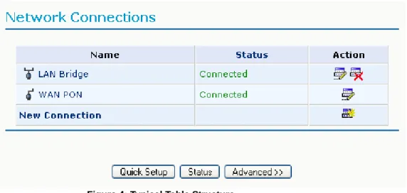
Managing Tables
Tables are structures used throughout the Web-based management. They handle user-defined entries relating to elements such as network connections, local servers, restrictions and configurable parameters. The principles outlined in this section apply to all tables in the Web-based management.
Figure 4: Typical Table Structure
Each row defines an entry in the table. The following buttons located in the ‘Action’ column enable adding, editing, deleting and moving table entries:
Use the Add action icon to add a row to the table.
Use the Edit action icon to edit a row in the table.
Use the Remove action icon to remove a row from the table. Use the Move Up action icon to move a row one step up in the table. Use the Move Down action icon to move a row one step down in the table.
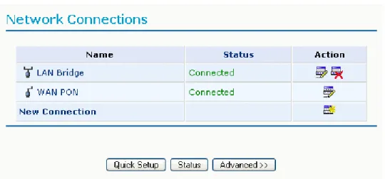
The zNID supports various network connections, both physical and logical. The Network Connections screen enables you to configure the various parameters of your physical connections, the LAN and WAN, and create new connections, using tunneling protocols over existing connections, such as PPP and VPN. When clicking the ‘Network Connections’ icon on the sidebar for the first time, the following typical screen will appear:
Figure 5: Network Connections - Basic
Press the ‘Advanced’ button to expand the screen and display all connection entries.
Figure 6: Network Connections - Advanced
This chapter describes the different network connections available with the zNID in their order of appearance in the Network Connections screen, as well as the connection types that you can create using the Connection Wizard.
Note: Some of the connections described herein may not be available with certain versions.
The zNID’s default network connections are: • LAN - Creating a home/SOHO network – LAN Bridge
– LAN Ethernet
• WAN - Internet Connection – WAN Ethernet
The logical network connections available with the zNID are: • WAN - Internet Connection
– Point-to-Point Protocol over Ethernet – Ethernet Connection
– Dynamic Host Configuration Protocol – Manual IP Address Configuration – Determine Protocol Type Automatically – WAN-LAN Bridge
• Advanced Connections – Network Bridging
– VLAN Interface
The Connection Wizard
The logical network connections can be easily created using the Connection Wizard. This wizard is consisted of a series of Web-based management screens, intuitively structured to gather all the information needed to create a logical connection.
Ethernet Gateway
In order to create a connection on an Ethernet gateway using the wizard, click the ‘New Connection’ link in the Network Connections screen. The
‘Connection Wizard’ screen will appear.
Figure 7: Connection Wizard
This screen presents you with the main connection types. Each option that you choose will lead you to further options in a tree-like formation, adding more information with each step and narrowing down the parameters towards the desired network connection.
Figure 8: Advanced Connection Wizard Screen
Figure 9: Advanced Connection Wizard Tree
Network Types
Every network connection in the zNID can be configured as one of three types: WAN, LAN or DMZ. This provides high flexibility and increased functionality.
For example, you may define that a LAN Ethernet connection on the zNID will operate as a WAN network. This means that all hosts in this LAN will be referred to as WAN computers, both by computers outside the zNID and by the zNID itself. WAN and firewall rules may be applied, such as on any other WAN network.
Another example, is that a network connection can be defined as a DMZ (Demilitarized) network. Although the network is physically inside the zNID, it will function as an unsecured, independent network, for which the zNID merely acts as a router.
One of these three network types is defined in each connection’s configuration screen, in the ‘Network’ combo-box, as depicted in the following sections.
DMZ Network
When defining a network connection as a DMZ network, you must also: • Remove the connection from under a bridge, if that is the case.
• Change the connection’s routing mode to “Route”, in the ‘Routing’ section of the configuration screen.
• Add a routing rule on your external gateway (which may be with your ISP) informing of the DMZ network behind the zNID.
LAN Bridge
The LAN bridge connection is used to combine several LAN devices under one virtual network.
Please note, that when a bridge is removed, its formerly underlying devices inherit the bridge’s DHCP settings. For example, the removal of a bridge that is configured as DHCP client, automatically configures the LAN devices formerly constituting the bridge as DHCP clients, with the exact DHCP client configuration.
Creation with the Connection Wizard
To configure an existing bridge or create a new one, perform the following steps:
1. Click the New Connection link in the ‘Network Connections’ screen. The ‘Connection Wizard’ screen will appear.
2. Select the Advanced Connection radio button and click Next. The ‘Advanced Connection’ screen will appear.
3. Select the Network Bridging radio button and click Next. The ‘Bridge Options’ screen will appear.
Figure 10: Bridge Options
4. Select whether to configure an existing bridge (this option will only appear if a bridge exists) or to add a new one:
(a) Configure Existing Bridge
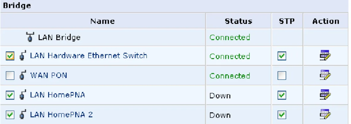
Select this option and click Next. The ‘Network Bridging’ screen will appear allowing you to add new connections or remove existing ones, by checking or unchecking their respective check boxes.
Figure 11: Network Bridging
For example, checking the WAN check box will create a LAN-WAN bridge. (b) Add a New Bridge
Select this option and click Next. A different ‘Network Bridging’ screen will appear allowing you to add a bridge over the unbridged connections, by checking their respective check boxes.
Important notes:
• The same connections cannot be shared by two bridges. • A bridge cannot be bridged.
• Bridged connections will lose their IP settings.
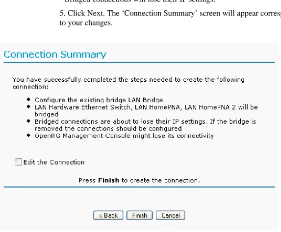
5. Click Next. The ‘Connection Summary’ screen will appear corresponding to your changes.
Figure 13: Connection Summary - Configure Existing Bridge
6. Check the ‘Edit the Newly Created Connection’ check box if you wish to be routed to the new connection’s configuration screen after clicking Finish. 7. Click Finish to save the settings.
The new bridge will be added to the network connections list, and will be configurable like any other bridge.
General
The top part of the configuration window displays general communication parameters. It is recommended not to change the default values in this screen unless you are familiar with the networking concepts they represent. Since your gateway is configured to operate with the default values, no parameter modification is necessary. You can configure the following general
Schedule By default, the connection will always be active. However, you can configure scheduler rules in order to define time segments during which the connection may be active. Once a scheduler rule(s) is defined, this field changes to a combo box, allowing you to choose between the available rules. To learn how to configure scheduler rules.
Network Select whether the parameters you are configuring relate to a WAN, LAN or DMZ connection, by selecting the connection type from the
combo-box. For more information.
Physical Address The physical address of the network card used for your network. Some cards allow you to change this address.
MTU MTU is the Maximum Transmission Unit. It specifies the largest packet size permitted for Internet transmission. The default setting, Manual, allows you to enter the largest packet size that will be transmitted. The recommended size is 1492.
You should leave this value in the 1200 to 1500 range. To have the gateway select the best MTU for your Internet connection, select Automatic.
Figure 14: General Bridge Settings
Internet Protocol
Select one of the following Internet Protocol options from the ‘Internet Protocol’ drop down menu:
• No IP Address
• Obtain an IP Address Automatically • Use the Following IP Address
Please note that according to the selection you make in the ‘Internet Protocol’ drop down menu, the screen will refresh and display relevant configuration settings.
No IP Address Select ‘No IP Address’ if you require that this connection will have no IP address. This can be useful if this connection is under a bridge.
Figure 15: Internet Protocol Settings – No IP Address
Use the Following IP Address The LAN connection is usually configured using a permanent (static) IP address. Your service provider should provide you with this address, and subnet mask.
Figure 16: Internet Protocol Settings – Static IP
Bridge Settings
The bridge section allows you to specify the LAN devices that you would like to join under the network bridge. Click the ‘Edit’ icon on the VLAN column to assign the network connections to specific Virtual LANS.
Select the ‘STP’ check box to enable the Spanning Tree Protocol on the device. You should use this to ensure that there are no loops in your network configuration, and apply these settings in case your network consists of multiple switches, or other bridges apart from those created by the gateway.
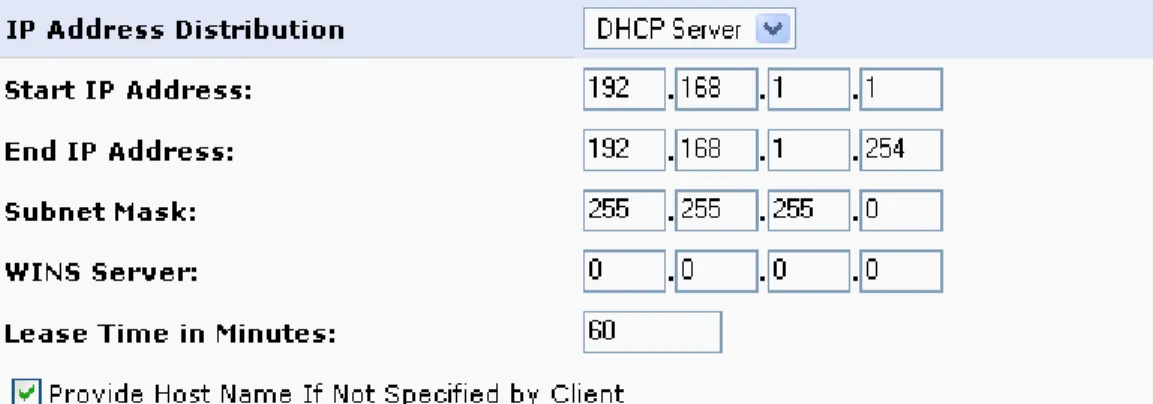
IP Address Distribution
The ‘IP Address Distribution’ section allows you to configure the gateway’s Dynamic Host Configuration Protocol (DHCP) server parameters. The DHCP automatically assigns IP addresses to network PCs. If you enable this feature, make sure that you also configure your network PCs as DHCP clients. Select one of the following options from the ‘IP Address Distribution’ combo-box:
• DHCP Server
Start IP Address The first IP address that may be assigned to a LAN host. Since the gateway’s default IP address is 192.168.1.1, this address must be 192.168.1.2 or greater.
End IP Address The last IP address in the range that can be used to automatically assign IP addresses to LAN hosts.
Subnet Mask A mask used to determine to what subnet an IP address belongs. An example of a subnet mask value is 255.255.0.0.
Lease Time In Minutes Each device will be assigned an IP address by the DHCP server for a this amount of time, when it connects to the network. When the lease expires the server will determine if the computer has disconnected from the network. If it has, the server may reassign this IP address to a newly-connected computer. This feature ensures that IP addresses that are not in use will become available for other computers on the network.
Provide Host Name If Not Specified by Client If the DHCP client does not have a host name, the gateway will automatically assign one.
Figure 18: IP Address Distribution – DHCP Server
• DHCP Relay
Your gateway can act as a DHCP relay in case you would like to dynamically assign IP addresses from a DHCP server other than your gateway’s DHCP server. Note that when selecting this option you must also change the zNID’s WAN to work in routing mode.
1. After selecting ‘DHCP Relay’ from the drop down menu, a ‘New IP Address’ link will appear:
Figure 19: IP Address Distribution - DHCP Relay
Click the ‘New IP Address’ link. The ‘DHCP Relay Server Address’ screen will appear:
Figure 20: DHCP Relay Server Address
2. Specify the IP address of the DHCP server. 3. Click ‘OK’ to save the settings.
• Disabled
Select ‘Disabled’ from the combo-box if you would like to statically assign IP addresses to your network computers.
Figure 21: IP Address Distribution - Disable DHCP
Routing
You can choose to setup your gateway to use static or dynamic routing. Dynamic routing automatically adjusts how packets travel on the network, whereas static routing specifies a fixed routing path to neighboring destinations.
Routing Select ‘Advanced’ or ‘Basic’ routing.
Route Use route mode if you want your gateway to function as a router between two networks.
NAPT Network Address and Port Translation (NAPT) refers to network address translation involving the mapping of port numbers, allowing multiple machines to share a single IP address. Use NAPT if your LAN encompasses multiple devices, a topology that necessitates port
translation in addition to address translation.
Device Metric The device metric is a value used by the gateway to determine whether one route is superior to another, considering parameters such as bandwidth, delay, and more.
Default Route Select this check box to define this device as a the default route.
Routing Information Protocol (RIP) Select this check box to enable the Routing Information Protocol (RIP). RIP determines a route based on the smallest hop count between source and destination. When RIP is enabled, select the following:
• Listen to RIP messages - select ‘None’, ‘RIPv1’, ‘RIPv2’ or ‘RIPv1/2’. • Send RIP messages - select ‘None’, ‘RIPv1’, ‘RIPv2-broadcast’ or ‘RIPv2-multicast’.
Multicast - IGMP Proxy Internal IGMP proxy enables the system to issue IGMP host messages on behalf of hosts that the system discovered through standard IGMP interfaces. IGMP proxy enables the routing of multicast packets according to the IGMP requests of LAN devices asking to join multicast groups. Select the ‘Multicast IGMP Proxy Internal’ check-box to enable this feature.
Routing Table Allows you to add or modify routes when this device is active. Use the ‘New Route’ button to add a route or edit existing routes.
Internet Connection Firewall
Your gateway’s firewall helps protect your computer by preventing unauthorized users from gaining access to it through a network such as the Internet. The firewall can be activated per network connection.
To enable the firewall on this network connection, select the ‘Enabled’ check box.
Figure 23: Internet Connection Firewall
Additional IP Addresses
You can add alias names (additional IP addresses) to the gateway by clicking the ‘New IP Address’ link. This enables you to access the gateway using these aliases in addition to the 192.168.1.1 and the http://zNID.home.
Figure 24: Additional IP addresses
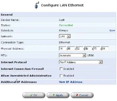
LAN Ethernet
A LAN Ethernet connection connects computers to the zNID using Ethernet cables, either directly or via network hubs and switches.
Clicking the “Settings” button at the bottom-right of the connection’s Properties window, will open its Configuration window:
Figure 26: LAN Ethernet Configuration
General
The top part of the configuration window displays general communication parameters. It is recommended not to change the default values in this screen unless you are familiar with the networking concepts they represent. Since your gateway is configured to operate with the default values, no parameter modification is necessary. You can configure the following general
connection settings:
Schedule By default, the connection will always be active. However, you can configure scheduler rules in order to define time segments during which the connection may be active. Once a scheduler rule(s) is defined, this field changes to a combo box, allowing you to choose between the available rules.
Network Select whether the parameters you are configuring relate to a WAN, LAN or DMZ connection, by selecting the connection type from the
combo-box.
Physical Address The physical address of the network card used for your network. Some cards allow you to change this address.
MTU MTU is the Maximum Transmission Unit. It specifies the largest packet size permitted for Internet transmission. The default setting, Manual, allows you to enter the largest packet size that will be transmitted. The recommended size, is 1492. You should leave this value in the 1200 to 1500 range. To have the gateway select the best MTU for your Internet connection, select
Automatic.
Internet Protocol
Select one of the following Internet Protocol options from the ‘Internet Protocol’ drop down menu:
• No IP Address
• Obtain an IP Address Automatically • Use the Following IP Address
Please note that according to the selection you make in the ‘Internet Protocol’ drop down menu, the screen will refresh and display relevant configuration settings.
No IP Address Select ‘No IP Address’ if you require that this connection will have no IP address. This can be useful if this connection is under a bridge.
Figure 27: Internet Protocol Settings – No IP Address
Use the Following IP Address The LAN connection is usually configured using a permanent (static) IP address. Your service provider should provide you with this address, and subnet mask.
Figure 28: Internet Protocol Settings – Static IP
IP Address Distribution
The ‘IP Address Distribution’ section allows you to configure the gateway’s Dynamic Host Configuration Protocol (DHCP) server parameters. The DHCP automatically assigns IP addresses to network PCs. If you enable this feature, make sure that you also configure your network PCs as DHCP clients.
Select one of the following options from the ‘IP Address Distribution’ combo-box:
• DHCP Server
Start IP Address The first IP address that may be assigned to a LAN host. Since the gateway’s default IP address is 192.168.1.1, this address must be 192.168.1.2 or greater.
End IP Address The last IP address in the range that can be used to automatically assign IP addresses to LAN hosts.
Subnet Mask A mask used to determine to what subnet an IP address belongs. An example of a subnet mask value is 255.255.0.0.
Lease Time In Minutes Each device will be assigned an IP address by the DHCP server for a this amount of time, when it connects to the network. When the lease expires the server will determine if the computer has disconnected from the network. If it has, the server may reassign this IP address to a newly-connected computer. This feature ensures that IP addresses that are not in use will become available for other computers on the network.
Provide Host Name If Not Specified by Client If the DHCP client does not have a host name, the gateway will automatically assign one for him.
Figure 29: IP Address Distribution – DHCP Server
• DHCP Relay
Your gateway can act as a DHCP relay in case you would like to dynamically assign IP addresses from a DHCP server other than your gateway’s DHCP server. Note that when selecting this option you must also change the zNID’s WAN to work in routing mode.
1. After selecting ‘DHCP Relay’ from the drop down menu, a ‘New IP Address’ link will appear:
Figure 30: IP Address Distribution - DHCP Relay
Click the ‘New IP Address’ link. The ‘DHCP Relay Server Address’ screen will appear:
Figure 31: DHCP Relay Server Address
2. Specify the IP address of the DHCP server. 3. Click ‘OK’ to save the settings.
• Disabled
Select ‘Disabled’ from the combo-box if you would like to statically assign IP addresses to your net- work computers.
Figure 29. IP Address Distribution - Disable DHCP
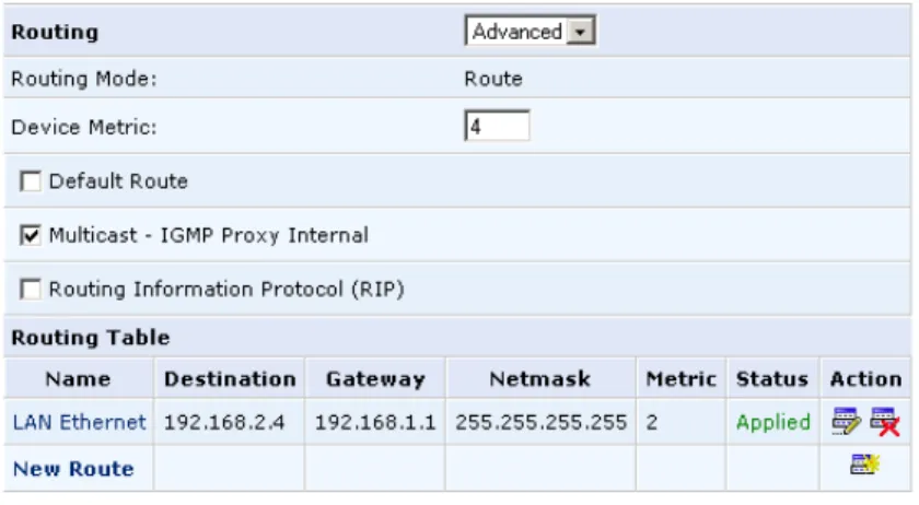
Routing
You can choose to setup your gateway to use static or dynamic routing. Dynamic routing automatically adjusts how packets travel on the network, whereas static routing specifies a fixed routing path to neighboring destinations.
Routing Select ‘Advanced’ or ‘Basic’ routing.
Routing Mode Select one of the following routing modes:
Route Use route mode if you want your gateway to function as a router between two networks.
NAPT Network Address and Port Translation (NAPT) refers to network address translation involving the mapping of port numbers, allowing multiple machines to share a single IP address. Use NAPT if your LAN encompasses multiple devices, a topology that necessitates port
translation in addition to address translation.
Device Metric The device metric is a value used by the gateway to determine whether one route is superior to another, considering parameters such as bandwidth, delay, and more.
Default Route Select this check box to define this device as a the default route.
Multicast - IGMP Proxy Internal IGMP proxy enables the system to issue IGMP host messages on behalf of hosts that the system discovered through standard IGMP interfaces. IGMP proxy enables the routing of multicast packets according to the IGMP requests of LAN devices asking to join multicast groups. Select the ‘Multicast IGMP Proxy Internal’ check-box to enable this feature.
Routing Table Allows you to add or modify routes when this device is active. Use the ‘New Route’ button to add a route or edit existing routes.
Figure 32: Advanced Routing Properties
Internet Connection Firewall
Your gateway’s firewall helps protect your computer by preventing unauthorized users from gaining access to it through a network such as the Internet. The firewall can be activated per network connection.
To enable the firewall on this network connection, select the ‘Enabled’ check box.
Figure 33: Internet Connection Firewall
Additional IP Addresses
You can add alias names (additional IP addresses) to the gateway by clicking the ‘New IP Address’ link. This enables you to access the gateway using these aliases in addition to the 192.168.1.1 and the http://zNID.home.
General
The top part of the configuration window displays general communication parameters. It is recommended not to change the default values in this screen unless you are familiar with the networking concepts they represent. Since your gateway is configured to operate with the default values, no parameter modification is necessary. You can configure the following general
connection settings:
Schedule By default, the connection will always be active. However, you can configure scheduler rules in order to define time segments during which the connection may be active. Once a scheduler rule(s) is defined, this field changes to a combo box, allowing you to choose between the available rules.
Network Select whether the parameters you are configuring relate to a WAN, LAN or DMZ connection, by selecting the connection type from the
combo-box. The physical address of the network card used for your network. Some cards allow you to change this address.
Clone MAC Allows you to copy the current MAC address of your PC to the MAC address of this device.
MTU MTU is the Maximum Transmission Unit. It specifies the largest packet size permitted for Internet transmission. In the default setting, Automatic, the gateway selects the best MTU for your Internet connection. In case you change to manual, you can enter the largest packet size, you should leave this value in the 1200 to 1500 range.
Figure 36: WAN Ethernet configuration
Internet Protocol Settings
Select one of the following Internet Protocol options from the ‘Internet Protocol’ drop down menu:
• No IP Address
• Obtain an IP Address Automatically • Use the Following IP Address
Please note that according to the selection you make in the ‘Internet Protocol’ drop down menu, the screen will refresh and display relevant configuration settings.
No IP Address Select ‘No IP Address’ if you require that your gateway have no IP address. This can be useful if you are working in an environment where you are not connected to other networks, such as the Internet.
Figure 35. Internet Protocol Settings – No IP Address
Obtain an IP Address Automatically Your WAN connection is configured by default to act as a DHCP client. You should keep this configuration in case your service provider supports DHCP, or if you are connecting using a dynamic IP address.
The server that assigns the gateway with an IP address, also assigns a subnet mask. You can override the dynamically assigned subnet mask by selecting the ‘Override Subnet Mask’ and specifying your own mask instead.
You can press the ‘Release’ button to release the current leased IP address. Once the address has been released, the button text changes to ‘Renew’. Use the ‘Renew’ button to renew the leased IP address.
Figure 37: Internet Protocol Settings – Automatic IP
Use the Following IP Address Your WAN connection can be configured using a permanent (static) IP address. Your service provider should provide you with this IP address, subnet mask and the default gateway IP address.
DNS Server
Domain Name System (DNS) is the method by which website or domain names are translated into IP addresses. You can configure the connection to automatically obtain a DNS server address, or specify such an address manually, according to the information provided by your ISP.
To configure the connection to automatically obtain a DNS server address, select ‘Obtain DNS Server Address Automatically’ from the ‘DNS Server’ drop down menu.
Figure 39: Automatic DNS Settings
To manually configure DNS server addresses, select ‘Use the Following DNS Server Addresses’ from the ‘DNS Server’ drop down menu. Specify up to two different DNS server address, one primary, another secondary.
Figure 40: DNS Settings
Routing
You can choose to setup your gateway to use static or dynamic routing. Dynamic routing automatically adjusts how packets travel on the network, whereas static routing specifies a fixed routing path to neighboring destinations.
Routing Select ‘Advanced’ or ‘Basic’ routing.
Routing Mode Select one of the following routing modes:
Route Use route mode if you want your gateway to function as a router between two networks.
NAPT Network Address and Port Translation (NAPT) refers to network address translation involving the mapping of port numbers, allowing multiple machines to share a single IP address. Use NAPT if your LAN encompasses multiple devices, a topology that necessitates port
translation in addition to address translation.
Device Metric The device metric is a value used by the gateway to determine whether one route is superior to another, considering parameters such as bandwidth, delay, and more.
Default Route Select this check box to define this device as a the default route.
Multicast - IGMP Proxy Internal IGMP proxy enables the system to issue IGMP host messages on behalf of hosts that the system discovered through standard IGMP interfaces. IGMP proxy enables the routing of multicast packets according to the IGMP requests of LAN devices asking to join multicast groups. Select the ‘Multicast IGMP Proxy Internal’ check-box to enable this feature.
Routing Table Allows you to add or modify routes when this device is active. Use the ‘New Route’ button to add a route or edit existing routes.
Figure 41: Advanced Routing Properties
Internet Connection Firewall
Your gateway’s firewall helps protect your computer by preventing unauthorized users from gaining access to it through a network such as the Internet. The firewall can be activated per network connection.
To enable the firewall on this network connection, select the ‘Enabled’ check box.
Figure 42: Internet Connection Firewall
Additional IP Addresses
You can add alias names (additional IP addresses) to the gateway by clicking the ‘New IP Address’ link. This enables you to access the gateway using these aliases in addition to the 192.168.1.1 and the http://zNID.home.
Figure 43: Additional IP Addresses
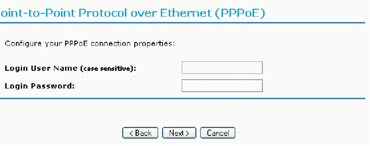
Point-to-Point Protocol over Ethernet (PPPoE)
Point-to-Point Protocol over Ethernet (PPPoE) relies on two widely accepted standards, PPP and Ethernet. PPPoE enables your home network PCs that communicate on an Ethernet network to exchange information with PCs on the Internet. PPPoE supports the protocol layers and authentication widely used in PPP and enables a point-to-point connection to be established in the normally multipoint architecture of Ethernet. A discovery process in PPPoE determines the Ethernet MAC address of the remote device in order to establish a session.
Creation with the Connection Wizard
To create a new PPPoE connection, perform the following steps:
1. Click the New Connection link in the ‘Network Connections’ screen. The ‘Connection Wizard’ screen will appear.
2. Select the Internet Connection radio button and click Next. The ‘Internet Connection’ screen will appear.
Figure 44: Point-to-Point Protocol over Ethernet
4. Enter the username and password provided by your Internet Service Provider (ISP), and click Next. The ‘Connection Summary’ screen will appear.
Figure 45: Connection Summary
5. Check the ‘Edit the Newly Created Connection’ check box if you wish to be routed to the new connection’s configuration screen after clicking Finish. 6. Click Finish to save the settings.
The new PPPoE connection will be added to the network connections list, and will be configurable like any other connection.
General
Schedule By default, the connection will always be active. However, you can configure scheduler rules in order to define time segments during which the connection may be active. Once a scheduler rule(s) is defined, this field changes to a combo box, allowing you to choose between the available rules.
Network Select whether the parameters you are configuring relate to a WAN, LAN or DMZ connection, by selecting the connection type from the combo-box.
MTU MTU is the Maximum Transmission Unit. It specifies the largest packet size permitted for Internet transmission. The default setting, Manual, allows you to enter the largest packet size that will be transmitted. The recommended size, is 1492. You should leave this value in the 1200 to 1500 range.
To have the gateway select the best MTU for your Internet connection, select Automatic.
Underlying Connection Specify the underlying connection above which the protocol will be initiated.
Figure 46: General PPPoE Settings
Internet Protocol
Select one of the following Internet Protocol options from the ‘Internet Protocol’ drop down menu:
• Obtain an IP Address Automatically • Use the Following IP Address
Please note that according to the selection you make in the ‘Internet Protocol’ drop down menu, the screen will refresh and display relevant configuration settings.
Obtain an IP Address Automatically Your PPP connection is configured by default to obtain an IP automatically. You should change this configuration in case your service provider requires it.
The server that assigns the gateway with an IP address, also assigns a subnet mask. You can override the dynamically assigned subnet mask by selecting the ‘Override Subnet Mask’ and specifying your own mask instead.
Figure 47: Internet Protocol Settings – Automatic IP
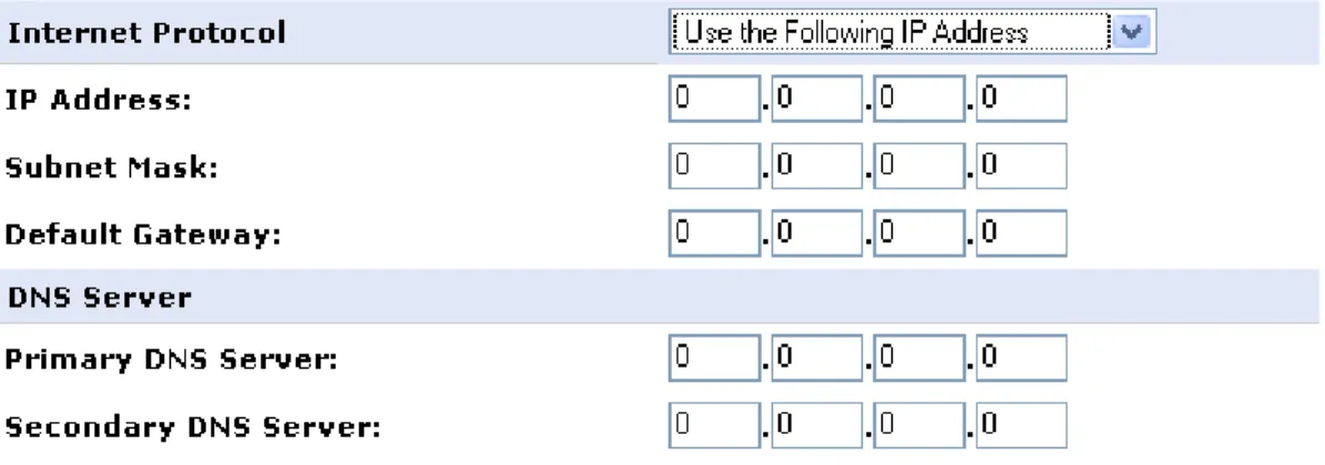
Use the Following IP Address Your WAN connection can be configured using a permanent (static) IP address. Your service provider should provide you with this IP address, subnet mask and the default gateway IP address.
Figure 48: Internet Protocol Settings – Static IP
DNS Server
Domain Name System (DNS) is the method by which website or domain names are translated into IP addresses. You can configure the connection to automatically obtain a DNS server address, or specify such an address manually, according to the information provided by your ISP.
To configure the connection to automatically obtain a DNS server address, select ‘Obtain DNS Server Address Automatically’ from the ‘DNS Server’ drop down menu.
Figure 49: Automatic DNS Settings
To manually configure DNS server addresses, select ‘Use the Following DNS Server Addresses’ from the ‘DNS Server’ drop down menu. Specify up to two different DNS server address, one primary, another secondary.
Figure 50: DNS Settings
Routing
You can choose to setup your gateway to use static or dynamic routing. Dynamic routing automatically adjusts how packets travel on the network, whereas static routing specifies a fixed routing path to neighboring destinations.
Routing Mode Select one of the following routing modes:
Route Use route mode if you want your gateway to function as a router between two networks.
NAPT Network Address and Port Translation (NAPT) refers to network address translation involving the mapping of port numbers, allowing multiple machines to share a single IP address. Use NAPT if your LAN encompasses multiple devices, a topology that necessitates port
translation in addition to address translation.
Device Metric The device metric is a value used by the gateway to determine whether one route is superior to another, considering parameters such as bandwidth, delay, and more.
Default Route Select this check box to define this device as a the default route.
Multicast - IGMP Proxy Internal IGMP proxy enables the system to issue IGMP host messages on behalf of hosts that the system discovered through standard IGMP interfaces. IGMP proxy enables the routing of multicast packets according to the IGMP requests of LAN devices asking to join multicast groups. Select the ‘Multicast IGMP Proxy Internal’ check-box to enable this feature.
Routing Table Allows you to add or modify routes when this device is active. Use the ‘New Route’ button to add a route or edit existing routes.
Figure 51: Advanced Routing Properties
Internet Connection Firewall
Your gateway’s firewall helps protect your computer by preventing unauthorized users from gaining access to it through a network such as the Internet. The firewall can be activated per network connection.
To enable the firewall on this network connection, select the ‘Enabled’ check box.
Figure 52: Internet Connection Firewall
Ethernet Connection
The Ethernet connection wizard utility is one of the three methods used to configure the physical WAN Ethernet connection. It is the most basic method, intended for connections that do not require user name and password in order to connect to the Internet.
To configure a new Ethernet connection, perform the following steps: 1. Click the New Connection link in the ‘Network Connections’ screen. The ‘Connection Wizard’ screen will appear.
2. Select the Internet Connection radio button and click Next. The ‘Internet Connection’ screen will appear.
3. Select the External Cable Modem radio button and click Next. The ‘Internet Cable Modem Connection’ screen will appear.
4. Select the ‘Ethernet Connection’ radio button and click Next. The ‘Connection Summary’ screen will appear.
Figure 54: Connection Summary
5. Check the ‘Edit the Newly Created Connection’ check box if you wish to be routed to the new connection’s configuration screen after clicking Finish. 6. Click Finish to save the settings.
The WAN Ethernet connection will be configured accordingly.
Dynamic Host Configuration Protocol (DHCP)
The Dynamic Host Configuration Protocol (DHCP) connection wizard utility is one of the three methods used to configure the physical WAN Ethernet connection. It is a dynamic negotiation method, where the client obtains an IP address automatically from the service provider when connecting to the Internet.
To configure a new DHCP connection, perform the following steps:
1. Click the New Connection link in the ‘Network Connections’ screen. The ‘Connection Wizard’ screen will appear.
2. Select the Internet Connection radio button and click Next. The ‘Internet Connection’ screen will appear.
3. Select the Ethernet Connection radio button and click Next. The ‘Ethernet Connection’ screen will appear.
Figure 55: Ethernet Connection
4. Select the ‘Dynamic Negotiation (DHCP)’ radio button and click Next. The ‘Connection Summary’ screen will appear.
Figure 56: Connection Summary
5. Check the ‘Edit the Newly Created Connection’ check box if you wish to be routed to the new connection’s configuration screen after clicking Finish. 6. Click Finish to save the settings.
The WAN Ethernet connection will be configured to obtain an IP address using a DHCP.
WAN-LAN Bridge
WAN bridge creates a bridge over WAN and LAN devices. This way
computers on the zNID LAN side can get IP addresses that are known on the WAN side.
Creation with the Connection Wizard
To configure an existing bridge or create a new one, perform the following steps:
1. Click the New Connection link in the ‘Network Connections’ screen. The ‘Connection Wizard’ screen will appear.
2. Select the Advanced Connection radio button and click Next. The ‘Advanced Connection’ screen will appear.
3. Select the Network Bridging radio button and click Next. The ‘Bridge Options’ screen will appear.
Figure 57: Bridge Options
4. Select whether to configure an existing bridge (this option will only appear if a bridge exists) or to add a new one:
(a) Configure Existing Bridge Select this option and click Next.
The ‘Network Bridging’ screen will appear allowing you to add new connections or remove existing ones, by checking or unchecking their respective check boxes.
Figure 58: Network Bridging
For example, checking the WAN check box will create a LAN-WAN bridge. (b) Add a New Bridge
Select this option and click Next. A different ‘Network Bridging’ screen will appear allowing you to add a bridge over the unbridged connections, by checking their respective check boxes.
Figure 59: Network Bridging
Important notes:
• The same connections cannot be shared by two bridges. • A bridge cannot be bridged.
• Bridged connections will lose their IP settings. 5. Click Next.
The ‘Connection Summary’ screen will appear, corresponding to your changes.
Figure 60: Connection Summary - Configure Existing Bridge
6. Check the ‘Edit the Newly Created Connection’ check box if you wish to be routed to the new connection’s configuration screen after clicking Finish. 7. Click Finish to save the settings.
The new bridge will be added to the network connections list, and will be configurable like any other bridge.
General
The top part of the configuration window displays general communication parameters. It is recommended not to change the default values in this screen unless you are familiar with the networking concepts they represent. Since your gateway is configured to operate with the default values, no parameter modification is necessary. You can configure the following general
connection settings:
Schedule By default, the connection will always be active. However, you can configure scheduler rules in order to define time segments during which the connection may be active. Once a scheduler rule(s) is defined, this field changes to a combo box, allowing you to choose between the available rules.
Network Select whether the parameters you are configuring relate to a WAN, LAN or DMZ connection, by selecting the connection type from the combo-box.
Physical Address The physical address of the network card used for your network. Some cards allow you to change this address.
Clone MAC Allows you to copy the current MAC address of your PC to the MAC address of this device.
MTU MTU is the Maximum Transmission Unit. It specifies the largest packet size permitted for Internet transmission. In the default setting,
Automatic, the gateway selects the best MTU for your Internet connection. In case you change to manual, you can enter the largest packet size, you should leave this value in the 1200 to 1500 range.
Figure 61: General WAN Bridge Settings
Internet Protocol Settings
Select one of the following Internet Protocol options from the ‘Internet Protocol’ drop down menu:
• No IP Address
• Obtain an IP Address Automatically • Use the Following IP Address
Please note that according to the selection you make in the ‘Internet Protocol’ drop down menu, the screen will refresh and display relevant configuration settings.
No IP Address Select ‘No IP Address’ if you require that your gateway have no IP address. This can be useful if you are working in an environment where you are not connected to other networks, such as the Internet.
Figure 61. Internet Protocol Settings – No IP Address
Obtain an IP Address Automatically Your WAN connection is configured by default to act as a DHCP client. You should keep this configuration in case your service provider supports DHCP, or if you are connecting using a dynamic IP address.
The server that assigns the gateway with an IP address, also assigns a subnet mask. You can override the dynamically assigned subnet mask by selecting the ‘Override Subnet Mask’ and specifying your own mask instead.
You can press the ‘Release’ button to release the current leased IP address. Once the address has been released, the button text changes to ‘Renew’. Use the ‘Renew’ button to renew the leased IP address.
Figure 62. Internet Protocol Settings – Automatic IP
Use the Following IP Address Your WAN connection can be configured using a permanent (static) IP address. Your service provider should provide you with this IP address, subnet mask and the default gateway IP address.
Figure 62: Internet Protocol Settings – Static IP
Bridge Settings
The bridge section allows you to specify the LAN and WAN devices that you would like to join under the network bridge. Click the ‘Edit’ icon on the VLAN column to assign the network connections to specific Virtual LANS. Select the ‘STP’ check box to enable the Spanning Tree Protocol on the device. You should use this to ensure that there are no loops in your network configuration, and apply these settings in case your network consists of multiple switches, or other bridges apart from those created by the gateway.
Figure 63: Bridge Settings
DNS Server
Domain Name System (DNS) is the method by which website or domain names are translated into IP addresses. You can configure the connection to automatically obtain a DNS server address, or specify such an address manually, according to the information provided by your ISP.
To configure the connection to automatically obtain a DNS server address, select ‘Obtain DNS Server Address Automatically’ from the ‘DNS Server’ drop down menu.
Figure 64: Automatic DNS Settings
To manually configure DNS server addresses, select ‘Use the Following DNS Server Addresses’ from the ‘DNS Server’ drop-down menu. Specify up to two different DNS server address, one primary, another secondary.
Routing
You can choose to setup your gateway to use static or dynamic routing. Dynamic routing automatically adjusts how packets travel on the network, whereas static routing specifies a fixed routing path to neighboring destinations.
Routing Select ‘Advanced’ or ‘Basic’ routing.
Routing Mode Select one of the following routing modes:
Route Use route mode if you want your gateway to function as a router between two networks.
NAPT Network Address and Port Translation (NAPT) refers to network address translation involving the mapping of port numbers, allowing multiple machines to share a single IP address. Use NAPT if your LAN encompasses multiple devices, a topology that necessitates port
translation in addition to address translation.
Device Metric The device metric is a value used by the gateway to determine whether one route is superior to another, considering parameters such as bandwidth, delay, and more.
Default Route Select this check box to define this device as a the default route.
Multicast - IGMP Proxy Internal IGMP proxy enables the system to issue IGMP host messages on behalf of hosts that the system discovered through standard IGMP interfaces. IGMP proxy enables the routing of multicast packets according to the IGMP requests of LAN devices asking to join multicast groups. Select the ‘Multicast IGMP Proxy Internal’ check-box to enable this feature.
Routing Table Allows you to add or modify routes when this device is active. Use the ‘New Route’ button to add a route or edit existing routes.
Internet Connection Firewall
Your gateway’s firewall helps protect your computer by preventing unauthorized users from gaining access to it through a network such as the Internet. The firewall can be activated per network connection.
To enable the firewall on this network connection, select the ‘Enabled’ check box.
Figure 67: Internet Connection Firewall
Additional IP Addresses
You can add alias names (additional IP addresses) to the gateway by clicking the ‘New IP Address’ link. This enables you to access the gateway using these aliases in addition to the 192.168.1.1 and the http://zNID.home.
Figure 69. Additional IP Addresses
Virtual LAN Interface (VLAN)
The zNID allows you to create Virtual LAN (VLAN) interfaces in order to connect to external virtual networks.
Creation with the Connection Wizard
To create a new VLAN interface, perform the following steps:
1. Click the New Connection link in the ‘Network Connections’ screen. The ‘Connection Wizard’ screen will appear.
2. Select the Advanced Connection radio button and click Next. The ‘Advanced Connection’ screen will appear.
3. Select the VLAN Interface radio button and click Next. The ‘VLAN Interface’ screen will appear.
Figure 68: VLAN Interface
4. Select the underlying device for this interface. The combo box will display the zNID’s Ethernet connections.
5. Enter a value that will serve as the VLAN ID, and click Next. The ‘Connection Summary’ screen will appear.
Figure 69: Connection Summary
6. Check the ‘Edit the Newly Created Connection’ check box if you wish to be routed to the new connection’s configuration screen after clicking Finish. 7. Click Finish to save the settings.
The new VLAN interface will be added to the network connections list, and will be configurable like any other connection.
General
The top part of the configuration window displays general communication parameters. It is recommended not to change the default values in this screen unless you are familiar with the networking concepts they represent. Since your gateway is configured to operate with the default values, no parameter modification is necessary. You can configure the following general
connection settings:
Schedule By default, the connection will always be active. However, you can configure scheduler rules in order to define time segments during which the connection may be active. Once a scheduler rule(s) is defined, this field changes to a combo box, allowing you to choose between the available rules.
Network Select whether the parameters you are configuring relate to a WAN, LAN or DMZ connection, by selecting the connection type from the combo-box.
Physical Address The physical address of the network card used for your network. Some cards allow you to change this address.
Clone MAC Allows you to copy the current MAC address of your PC to the MAC address of this device.
MTU MTU is the Maximum Transmission Unit. It specifies the largest packet size permitted for Internet transmission. In the default setting, Automatic, the gateway selects the best MTU for your Internet connection. In case you change to manual, you can enter the largest packet size, you should leave this value in the 1200 to 1500 range.
Underlying Connection The Ethernet device that the connection is implemented over.
Internet Protocol
Select one of the following Internet Protocol options from the ‘Internet Protocol’ drop down menu:
• No IP Address
• Obtain an IP Address Automatically • Use the Following IP Address
Please note that according to the selection you make in the ‘Internet Protocol’ drop down menu, the screen will refresh and display relevant configuration settings.
No IP Address Select ‘No IP Address’ if you require that your gateway have no IP address. This can be useful if you are working in an environment where you are not connected to other networks, such as the Internet.
Obtain an IP Address Automatically Your WAN connection is configured by default to act as a DHCP client. You should keep this configuration in case your service provider supports DHCP, or if you are connecting using a dynamic IP address.
The server that assigns the gateway with an IP address, also assigns a subnet mask. You can override the dynamically assigned subnet mask by selecting the ‘Override Subnet Mask’ and specifying your own mask instead.
You can press the ‘Release’ button to release the current leased IP address. Once the address has been released, the button text changes to ‘Renew’. Use the ‘Renew’ button to renew the leased IP address.
Figure 71: Internet Protocol Settings – Automatic IP
Use the Following IP Address Your WAN connection can be configured using a permanent (static) IP address. Your service provider should provide you with this IP address, subnet mask and the default gateway IP address.
Figure 72: Internet Protocol Settings – Static IP
IP Address Distribution
The ‘IP Address Distribution’ section allows you to configure the gateway’s Dynamic Host Configuration Protocol (DHCP) server parameters. The DHCP automatically assigns IP addresses to network PCs. If you enable this feature, make sure that you also configure your network PCs as DHCP clients. Select one of the following options from the ‘IP Address Distribution’ combo-box: