Three-Dimensional Rock Fall
Simulation, Considering Collisions
and Their Eects on the Hazard Map
N. Hataf
, M. Meidani
1and M. Veis Karami
2Every year, many deaths, injuries and much economic loss due to falling rocks and boulders occur to the people who live in and pass through mountainous regions worldwide. Closed transportation corridors and damage to infrastructures, like rock sheds, due to rock falls, are common phenomena in some countries, especially during rainfall or earthquake. Realistic simulation of rock falls, along with dening their most vulnerable fall trajectories, can result in providing mitigation measures in the right places with the least cost. While many numerical approaches have been developed to predict the trajectory of falling rocks, none of them consider the interaction between the blocks of falling objects. In this paper, a common discrete element software (i.e., Working Model 3D) has been employed as a new tool to model rock fall. The interaction between falling masses, i.e., the impact between falling rock blocks, is considered. The results are compared to those obtained from traditional rock fall simulations. While the recent approach gives a more realistic result, its drawback is the enormous time needed to perform calculations, i.e. more than ten to a hundred fold, depending on the number of falling objects involved. The results show that existing simulation techniques give a lower bound for the hazard zone scattering and, consequently, the measuring structures will not be very ecient. On the other hand, designers should over-design to cover unseen hazard zones, which lead to heavy project costs.
INTRODUCTION
There are many reports on rock fall events in moun-tainous regions and the severe damage to men's lives and structures every year. A very recent disastrous event was the Chaloos earthquake in 2004, followed by a number of rock falls in Northern Iran, where more than one hundred people died when huge blocks of rock crashed onto their cars (Figure 1). The rock fall hazard also extends to the foothills where generally populated areas are located. Some countermeasures, like rock sheds, fences, ditches, rail guards and berms are used to prevent or decrease damage to lives and properties [1]. The correct design and location of
*. Corresponding Author, Department of Civil Engineering, Shiraz University, Shiraz, I.R. Iran.
1. National Institute of Rural Engineering, Tsukuba-shi, Ibarakai, Japan.
2. Department of Civil Engineering, Shiraz University, Shi-raz, I.R. Iran.
these structures depend directly on the prevention of rock fall trajectories. Conventionally, these structures are designed with a high factor of safety, i.e., they usually protect a wider area than is obtained from analyses. However, some of these measures can cause secondary eects by diverting the falling rocks from their original path and by changing the hazard zone shape. The latter cannot be predicted very well within two-dimensional analyses. Therefore, some techniques have been introduced to model rock falls in three-dimensional space. The main shortage of current approaches to nding rock fall trajectories in three-dimensional space is that they do not consider interaction between falling masses, i.e., they consider each individual rock separately without any interaction with other masses during fall and landing. In this paper it is shown that if the latter phenomenon is considered, the acquired trajectory will be dierent and some areas that were considered outside the hazard zone, will become prone to falls. Having introduced a tool for three-dimensional simulation of rock fall, an
Figure 1.
a) The central Alborz mountainous region and its geological feature in Northern Iran; b) Rock falls following Chaloos earthquake (2004).example has been investigated thoroughly to show how the modeling of colliding masses can aect the extent of the hazard zone in three-dimensional space.
ROCK FALL MODELING
In addition to debris avalanches, which are huge in volume and cause vast destruction in mountainous areas, rock falls are another source of hazard in these regions. Debris avalanches have volumes of 107m3and
more, while rock falls consist of 102 to 105 m3 of rock.
Nevertheless, the kinematical energy of the individual rocks is so high as to make them comparable and even more destructive than debris ow [2]. The problem of debris avalanches has drawn much attention [3-8]. Complicated mathematical models have been proposed in this eld, along with many other invaluable stud-ies [9-12]. The main dierence between rock falls and debris avalanches is that, in the latter case, the whole mass of rock and stone is considered as a closed control volume and interaction between particle movement is very important, but, in a rock fall problem, each rock unit is considered as a discrete element and the
interaction between the elements can be neglected in the calculations [13]. This assumption has been the most important key to the latest developments in rock fall simulation techniques and all researchers have followed it. Although neglecting the interaction of individual particles of rock can simplify the model in analyzing the rock fall process, this assumption will lead to less than perfect results, in particular, when compared with a three-dimensional realistic model.
Since the rules of mechanics govern the falling rock [14], it is a precise dynamic problem. Two main approaches are used in analyzing rock fall problems: First, considering rock masses as lumped masses and, second, as rigorous masses [15]. Among many factors involved in a rock fall problem, two factors are more important in the analyses, restitution coecient and rolling friction coecient [16,17]. Rock blocks, gener-ally, have very complicated geometries and these even undergo major changes after high velocity impact with the ground, structures and other falling bodies. This fact, however, has not been considered in any of the existing rock fall simulation procedures and the falling mass remains intact till the end of simulation. From the lumped mass point of view, the geometry of the rock is not considered in the calculations.
Many programs, codes and models have been developed for two-dimensional analysis of rock falls [16,18-21]. While falling rocks attain six com-ponents of velocity after their several impacts with the ground, other structures and/or other falling rocks, their movement must be considered in three-dimensional space. Therefore, three-three-dimensional anal-ysis can be more correct when it is required to map hazard zones both cost eectively and at lower risk, resulting in a lowered factor of safety in the design of countermeasure structures and due to a better identication of rock fall prone areas. Very few studies have been performed on the three-dimensional analysis of rock falls, amongst which are Descoeudres & Zimmermann (1987), Guzzetti et al. (2002), Agliardi & Crosta (2003), Meidani & Hataf (2004) and Yang et al. (2004) [22,23,13,24,25].
WORKING MODEL 3D PROGRAM
In order to perform a realistic model of three-dimensional rock fall events, a commercially available program, named Working Model 3D (WM3D), which is a sophisticated, three-dimensional discrete element analysis program, is used. This program was originally developed for analyzing mechanical models, but, as long as the same laws of particle motion govern the motion of falling rocks, it can be used here as a new and exible tool to simulate rock fall in three-dimensional space. The program, WM3D, is capable of considering basic parameters for each element, while
these parameters can be functions of other parameters i.e., time or position of another element. To solve dierential equations of motion in a dynamic model, this program utilizes a numerical temporal integration approach [26].
WM3D can be used to model any type of problem that follows the rules of mechanics and dynamics; rock fall is such a problem. The procedure to simulate a rock fall problem is fully described through analysis of the coming example, based on a real problem in Northern Iran.
It is also possible to create any three-dimensional solid model in CAD based software and, then, by importing it into WM3D. Thus, many dierent rock shapes were created originally in CAD.
EXAMPLE: ROCK FALL INCIDENCE ON A
HIGHWAY
The Chaloos Highway is located in the north of Tehran and is one of the main corridors to the northern provinces of Iran. The main geological features and tectonic structures of Northern Iran are related to the quaternary age. The main geological feature of this area consists of igneous rocks expelled from the Alborz Mountains and its ancient active volcanoes. Very complex geological deformation features exist in that region. Figure 1 shows a typical geological feature of the central Alborz Mountains area [27].
Because this road is an important corridor to the northern provinces and the trac is heavy on this road, any rock fall event causes severe economic and humanitarian losses. One of the prone-to-rock fall parts of the Chaloos highway is shown in Figure 2. Many measures and protecting structures have been placed throughout the Chaloos highway to prevent rock fall hazard. Nevertheless, much damage and death caused by rock falls are reported every year in this
Figure 2.
A hazardous zone prone to rock fall problem on Chaloos highway, located in Northern Iran.Figure 3.
Protecting measure (retaining wall) for rock fall hazard on Chaloos highway.area. Figure 3 shows a retaining wall to prevent rock fall hazard on the Chaloos highway [27].
In this study, a length of about 180 m of this route is modeled. This zone was chosen because a weathered rock mass of about 80 m3was susceptible to
splitting and falling on the two roads passing at 65 m and 110 m lower down in the valley. To reduce the risk of rock fall, a rock shed was considered for the upper road and the secondary eects of the construction of this structure on the trajectory of a rock fall were investigated.
Problem Denition in 3D Working Model
The large weathered rock blocks were broken down to 128 smaller boulders of volumes around 0.5 m3, this was
according to the size of the discontinuities in the rock mass observed in the region. Four dierent boulder geometries were considered and reproduced to build up 128 boulders. The existing ditches and guard rails were also taken into account. A new rock trap (ditch) and a guard rail were predicted to reduce rock fall hazard, since the existing rock trap measures (ditch and guard rail) seemed to be ineective toward such a large volume of rock fall. The rock blocks and the cape geometry were modeled in AutoCAD and then imported into the program.
Since the eect of collision between rock blocks was intended to be investigated, two methods of analy-sis were considered; rst, the rocks were assumed to fall independently (without collision) and, second, the rock blocks were assumed to fall dependently (with collision) and the contact between individual rock blocks was taken into account in this approach. Although the assumption of an independent fall of rock blocks is acceptable and applicable, for a small volume of falling rocks [13,24], many shortcomings may arise in the case of huge volumes of mass.
Parameters
As cited, the two most important parameters in rock fall modeling are the coecient of restitution and rock friction coecient. For this simulation, these param-eters were chosen, as listed in Table 1, for dierent types of material considered according to Azzoni & de Freitas [28]. The rock blocks and the cape surface were assumed to be of the same material, as consistent with the eld characteristics of these materials.
Simulation Process
The problem was rst analyzed without considering the collision between rock blocks and falling trajectories. In the next stage, another analysis was performed considering the collision between falling rocks. These two simulations were performed, based on the realistic mechanical properties of the rock blocks, which are listed in Table 1. The model parameters were chosen by comparing the site rock properties that have been reported in geological reports of this area with dierent materials reported in [28]. The working model 3D pro-gram employed these properties for dierent elements to simulate the rock fall.
Results and Discussion
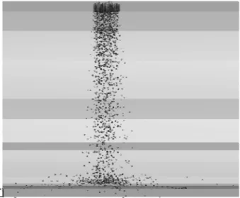
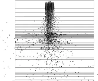
Figures 4 to 6 show the envelopes of falling rock when the rocks fall independently (without a collision eect). Figures 7 to 9 represent the falling envelopes when the rock fall simulation was performed under more realistic conditions. In the latter case, rocks were allowed to feel each other during movement.
It is apparently obvious from the results of these two dierent approaches that the rock fall envelope is very dierent in these two models. While there is a limited extent for rock fall envelope in the model without a colliding eect, in the other case, i.e., when the collision eect is considered, a much wider zone of rock fall hazard can be observed. Comparing the width of the zones in the front view representation of hazard envelopes for two models (Figures 4 and 7, respectively), in the cases where the rocks fall without
Table 1.
Material properties used in the analysis.Material
of Restitution
Coecient
Coecient
Friction
(kg/m
Density
3)
Rocks 0.40 0.75 2400 Ground 0.40 0.75 2400 Asphalt 0.30 0.80 N.N
River Bed 0.15 1.00 N.N Guard Rail 0.15 1.00 N.N
* N.N: Not needed in the calculations
Figure 4.
Front view of falling rock envelope (without collision consideration).Figure 5.
Side view of falling rock envelope (without collision consideration).Figure 6.
Aerial view of falling rock envelope (without collision consideration).Figure 7.
Front view of falling rock envelope (with collision consideration).Figure 8.
Side view of falling rock envelope (with collision consideration).Figure 9.
Aerial view of falling rock envelope (with collision consideration).collision, the critical width of the hazard zone is about three times the width of the unstable rock area on the top of the cape. However, in the other case, it is more than 5 to 6 times the width of the unstable rock area on the top of the cape. It should be noted that this width is assumed to be the area in which more than 85% of rock mass falls through, i.e., the total width cannot be measured accurately because of the scatter of the falling rocks, especially in the second case.
By counting the number of rocks touching the ground behind the guard rail and contacting with the highway pavement, it is observed that, in the model without collision, the total number of rocks remaining on the ground behind the guard is equal to 72 and 56 rocks lay on the pavement. This makes 43% of the total falling bodies.
However, in the model with collision, there are 92 total rock blocks that hit the ground behind the guard, 39 of which are thrown on the road pavement after touching the ground. Considering that 39 rocks directly fall on the road surface, a total number of 75 rock blocks are lying on the road at the end of the analysis, which is 59% of all falling rocks.
Table 2 shows the result of falling rocks and compares the two models. Comparing the results, it can be realized that there will be about 35% inaccuracy if collision between rock blocks is neglected.
As a nal result, the scatter of the falling rock envelopes in the top view gures (Figures 6 and 9 in two models) shows that, in a rock fall model, considering the contact between the rock blocks, a wider range and more precise zone of hazard can be achieved. However, in simpler models (i.e., modeling with neglecting the collision) the zone will be reduced considerably and many errors may arise in determina-tion of the real hazard zone. These results are less than perfect for the prediction and design of retaining structures.
Table 2.
Summary of the rock fall simulation results.Parameters
without
Model
Collide
Model
with
Collide
No. of rocks remaining
behind the guard 72 53 No. of rocks thrown on the
road pavement after hitting the ground behind the guard
56 75
No. of rocks directly fallen
on the road surface 10 39
*: The result contains the number of rocks fallen on the road and thrown in the valley after hitting the road.
CONCLUSIONS AND SUMMARY
A new tool for modeling rock fall problems, i.e., Work-ing Model 3D software, as a powerful and exible tool for dierent types of rock fall analysis, was introduced. Through the analysis of a case study, the capabilities of this software were demonstrated and the results of a special problem were discussed.
In this paper, a practical case study was investi-gated and a zone that is prone to rock fall through a mountainous area in northern Iran was modeled. Two dierent design approaches were considered; rst, the rocks were assumed to be falling without inter-action, i.e., without collision and, second, the rocks were assumed to be in contact with each other while falling. The results of the two models show that the \without-collide" model results dier at about 35% in the prediction of rocks hitting the road surface in comparison with the \with-collide" model. A wide range of hazardous area is also achieved (about 5 to 6 times the width of the unstable rocks on the top of the cape) in the with-collide model that contains more than 85% of the falling rock. However, for the without-collide model, the width of the hazard zone is just a half of the latter. So, in the design of rock fall protecting measures, more precise models and careful estimates of real rock fall problems are needed.
It, therefore, can be concluded that however many design charts are available for the designers to consider countermeasure structures, while each site has its own geomorphological characteristics, these charts may lead to over-designed structures and some hazard prone areas maybe ignored [20].
Since the conventional methods do not consider the real site geomorphological properties and do not take into account collisions between falling masses, these methods cannot precisely predict rock fall hazard. But, by using the real site geomorphology in a three-dimensional space and allowing the falling bodies to interact with each other, the results will be more precise and closer to actual rock fall behavior for any given case. Thus, the performance of this method resembles a closer and more realistic model of rock fall hazard, with respect to real site geomorphology and rock blocks behavior. It is, therefore, strongly recommended that the design engineers model their own problems to decrease both the costs of the project and to avoid any unseen hazard zone which would increase loss of life.
ACKNOWLEDGMENTS
The second author wishes to thank the Iranian Ministry of Science, Research and Technology for granting the post graduate scholarship during the course of this study.
REFERENCES
1. Hoek, E. \Practical rock engineering handbook", Roc-science, website: http://www.rocscience.com (2000). 2. Rochet, L. \Application des modeles numeriques de
propagation a letude des eboulements rocheux",Bull Liaison Pont Chaussee,
150/151
, pp 84-95 (1987). 3. Li, T. \A mathematical model for predicting the extentof a major rock fall",Zeitschrift Fuer Geomorphologie,
24
, pp 473-482 (1983).4. Ayotte, D. and Hungr, O. \Runout analysis of debris ows and debris avalanches in Hong Kong",Report of the Geotechnical Engineering Oce, Hong Kong SAR Government (1998).
5. Iverson, R.M. and Vallance, J.W. \New views of granular mass ows", Geological Society of America. Geology,
29
(2), pp 115-118 (2001)6. Tai, Y.C., Huttur, K. and Gray, J.M.N.T. \Dense granular avalanches: Mathematical description and experimental validation", Lecture Notes in Physics,
582
, Geomorphological Fluid Dynamics, Springer, pp 339-366 (2001)7. Staron, L., Vilotte, J.P. and Radjai, F. \Friction and mobilization of contacts in granular numerical avalanches",Powders and Grains, pp 451-454 (2001). 8. Friedmann, S.S., Kwon, G. and Losert, W. \Granular
memory and its eect on the triggering and distri-bution of rock avalanche events", J. of Geophysical Research,
108
(B8), p 2380 (2003).9. Heim, A. \Bergsturz und Menchenleben", Zurich,
Vierteljahrsschrift,
77
(20), p 218 (1932).10. Scheidegger, A.E. \On the prediction of the reach and velocity of catastrophic landslides", Rock Mechanics,
5
, pp 231-236 (1974).11. Hungr, O., Evans, S.G. and Hazzard, J. \Magnitude and frequency of rock falls and rockslides along the main transportation corridors of southwestern British Columbia",Canadian Geotechnical Journal,
36
(2), pp 224-238 (1999).12. Singh, N.K. and Vick, S.G. \Probabilistic rock fall haz-ard assessment for roadways in mountainous terrain",
3rd Canadian Conf. on Geotechnique and Natural Hazards(2003).
13. Agliardi, F. and Crosta, G.B. \High resolution three-dimensional numerical modeling of rock falls",Int. J. of Rock Mechanics and Mining Science,
40
, pp 455-471 (2003).14. Bozzolo, D., Pamini, R. and Hutter, K. \Rock fall analysis - a mathematical model and its test with eld data", Proc. 5th Int. Symposium on Landslides, Lausanne, Switzerland (1988).
15. Giani, G.P. \Rock slope stability analysis", Balkema, Rotterdam, Netherlands (1992).
16. Azzoni, A., la Barbera, G. and Zaninetti, A. \Analysis and prediction of rock falls using a mathematical model", Int. J. Rock Mech. Min. Sci. & Geomech. Abstr.,
32
(7), pp 709-724 (1995).17. Chau, K.T., Wong, R.H.C. and Wu, J.J. \Coecient of restitution and rotational motions of rock fall im-pacts", Int. J. Rock Mech. Min. Sci.,
39
, pp 69-77 (2002).18. Hoek, E. \Rock fall: A computer program for predict-ing rock fall trajectories",Unpublished Internal Notes, Golder Associates, Vancouver, Canada (1986). 19. Pfeier, T.J. and Bowen, T.D. \Computer simulation
of rock falls",Bull. Assoc. Engrg. Geo.,
XXVI
(1), pp 135-146 (1989)20. Pierson, L.A., Gullixson, C.F. and Chassie, R.G. \Rock fall catchment area design guide, nal re-port", Oregon Department of Transportation, OR, USA (2001).
21. Krauter, E. and Spang, R.M. \Rock fall sim-ulation - a state-of-the-art tool for risk assess-ment and dimensioning of rock fall barriers", http://www.geointernational.info.
22. Descoeudres, F. and Zimmermann, T. \Three-dimensional dynamic calculation of rock falls", Proc. 6th Int. Congress on Rock Mechanics, Montreal, Canada (1987).
23. Guzzetti, F., Crosta, G., Detti, R. and Agliardi, F. \STONE: A computer program for the three-dimensional simulation of rock-falls",Comput. Geosci,
28
(9), pp 1081-1095 (2002)24. Meidani, M. and Hataf, N. \A new tool for two and three-dimensional rock fall analysis and cross sectional hazard mapping; case study: Rock fall problem in Bolhayat cape, Shiraz-Ahwaz highway",Proc. 9th Int. Symposium on Landslides, Rio, Brazil, pp 515-520 (2004).
25. Yang, M., Fukawa, T., Ohnishi, Y., Nishiyama, S., Miki, S., Hirakawa, Y. and Mori, S. \The application of three-dimensional DDA with a spherical rigid block to rock fall simulation", SINOROCK 2004 paper 2B 25,Int. J. Rock Mech. Min. Sci.,
41
, p 476 (2004). 26. \Working Model 3D V.4.0 user's manual",KnowledgeRevolution, San Mateo, CA, USA (1998).
27. Memarian, H., Engineering Geology and Geotechnics, Tehran university press, p 974 (1992).
28. Azzoni, A. and de Freitas, M.H. \Experimentally gained parameters, decisive for rock fall analysis",Rock Mechanics and Rock Engineering,