Available online through
ISSN 2229 – 5046NUMERICAL SOLUTION OF THERMAL RADIATION AND HALL EFFECT ON MHD MIXED
CONVECTIVE FLOW OF A VISCOUS INCOMPRESSIBLE FLUID PAST A VERTICAL POROUS
PLATE IMMERSED IN POROUS MEDIUM WITH HEAT SOURCE/SINK
V. SRINIVASA RAO*
Department of Mathematics,
Anurag Group of Institutions, Hyderabad, Telangana, India.
Y. DHARMENDAR REDDY
Department of Mathematics,
Anurag Group of Institutions, Hyderabad, Telangana, India.
(Received On: 17-08-16; Revised & Accepted On: 06-09-16)
ABSTRACT
T
he objective of the study is to analyze the thermal radiation and Hall Effect on unsteady MHD mixed convective flow of a viscous incompressible fluid past an infinite vertical porous flat plate in the presence of a heat source/sink. The problem is solved numerically by using finite element method for velocity, temperature and concentration field and also the expression for skin friction have been obtained. The numerical results are demonstrated graphically for various values of the parameters including Hartman number, Prandtl number, Grashof number for heat and mass transfer, Schmidt number, Hall parameter, Radiation parameter and the heat source/sink parameter.Key words: MHD, mixed convection, vertical porous plate, thermal radiation, mass transfer, heat source/sink.
1. INTRODUCTION
The phenomenon of heat and mass transfer has been the object of extensive research due to its applications in science and technology. Such phenomenon is observed in buoyancy induced motions in the atmosphere, in bodies of water, quasi-solid bodies, such as earth and so on. The hydromagnetic convection with heat and mass transfer in porous medium has been studied due to its importance in the design of MHD generators and accelerators in geophysics, in design of underground water energy storage system, soil-sciences, astrophysics, nuclear power reactors and so on. Magnetohydrodynamics is currently undergoing a period of great enlargement and differentiation of subject matter. The interest in these new problems generates from their importance in liquid metals, electrolytes and ionized gases. On account of their varied importance, these flows have been studied by several authors – notable amongst them are Shercliff [1], Ferraro and Plumpton [2] and Crammer and Pai [3]. Hayat et al. [4] analyzed a mathematical model in order to study the heat and mass transfer characteristics in mixed convection boundary layer flow about a linearly stretching vertical surface in a porous medium filled with a viscoelastic fluid, by taking into account the diffusion thermo (Dufour) and thermal-diffusion (Soret) effects. Hossain and Rees [5] examined the effects of combined buoyancy forces from thermal and mass diffusion by natural convection flow from a vertical wavy surface. Numerical results were obtained to show the evolution of the surface shear stress, rate of heat transfer and surface concentration gradient. Recently, combined heat and mass transfer in MHD free convection from a vertical surface has been studied by Chen [6].
Thermal radiation is an important factor in the thermo dynamic analysis of many high temperature systems like solar connectors, boilers and furnaces. The simultaneous effect of heat and mass transfer in the presence of thermal radiation play an important role in manufacturing industries. For the design of fins, steel rolling, nuclear power plants, cooling of towers, gas turbines and various propulsion device for aircraft, combustion and furnace design, materials processing, energy utilization, temperature measurements, remote sensing for astronomy and space exploration, food processing and cryogenic engineering, as well as numerous agricultural, health and military applications. Radiation effect on mixed convection along a iso thermal vertical plate were studied by Hossain and Takhar [7]. Raptis and Perdikis [8] studied the effects of thermal radiation and free convection flow past a moving vertical plate. Further, the effect of Hall current on the fluid flow with variable concentration has many applications in MHD power generation, in several
astrophysical and meteorological studies as well as in plasma flow through MHD power generators. From the point of application, model studies on the Hall effect on free and forced convection flows have been made by several investigators. Aboeldahab [9], Datta et al. [10], Acharya et al. [11] and Biswal et al. [12] have studied the Hall effect on the MHD free and forced convection heat and mass transfer over a vertical surface. In the above mentioned studiesthe heat source/sink effect is ignored. Due to its great applicability to ceramic tiles production problems, the study of heat transfer in the presence of a heat source/sink has acquired newer dimensions. A number of analytical studies have been carried made of for various forms of heat generation (Ostrach [13–15], Raptis [16]). Singh [17] analyzed MHD free convection and mass transfer flow with heat source and thermal diffusion.
Motivated by the above reference work and the numerous possible industrial applications of the problem, it is of paramount interest in this study to investigate the thermal radiation and Hall Effects on the combined heat and mass transfer unsteady flow which occur due to buoyancy forces caused by thermal diffusion (temperature differences) and mass diffusion (concentration differences) of comparable magnitude past a vertical porous plate which is immersed in porous medium with a constant magnetic field applied perpendicular to the plate and heat source/sink.
2. MATHEMATICAL FORMULATION
Consider the unsteady flow of an electrically conducting fluid past an infinite porous vertical flat plate coinciding with the plane y = 0 such that the x-axis is along the plate and y-axis is normal to it. A uniform magnetic field Bo is applied in the direction y - axis and the plate is taken as electrically non-conducting. Taking z - axis normal to xy - plane and
assuming that the velocity
V
and the magnetic fieldH
have components (u, v, w) and (Hx, Hy, Hz) respectively, theequation of continuity
∇
.
V
= 0 and solenoidal relation∇
.
H
= 0 giveso
V
v
=
−
constant, Vo > 0 (1)From Maxwell’s electromagnetic field equations,
0
=
∂
∂
y
H
y(2)
If the magnetic Reynolds number is small, induced magnetic field is negligible in comparison with the applied magnetic field, so that [18]
Hx= Hz= 0 and Hy= Bo (constant).
If (Jx, Jy, Jz) are the components of electric current density
J
. The equation of conservation of electric charge
∇
.
J
=
0
gives,
Jy = constant. (3)
Since the plate is non-conducting, Jy= 0 at the plate and hence zero everywhere in the flow. Neglecting polarization
effect, we get
E
= 0. (4)Hence
(
J
J
)
H
(
B
)
V
(
u
V
w
)
J
=
x,
0
,
z,
=
0
,
o,
0
,
=
,
o,
(5)The generalized Ohm’s law including Hall current is given in the form
(
)
(
)
1
e e
e
o e
J
J
B
E
J
B
p
B
e
ω τ
σ
η
+
×
=
+
×
+
∇
(6)
In writing equation (6) ion slip, thermoelectric effects and polarization effects are neglected. Further, it is also assumed that
ω
eτ
e~ 0 andω
eτ
e≤
1
, whereω
e,ω
i are cyclone frequencies of electrons and ions, andτ
e,τ
i are collision times of electrons and ions.Where
V
is the velocity vector,E
is the electric field,ω
e is the electron frequency,τ
e is the electron collision time,vertical porous plate immersed in porous medium with heat source/sink / IJMA- 7(9), Sept.-2016.
(
)
(
)
+
+
=
−
+
=
mw
u
m
B
J
w
mu
m
B
J
o z o x 2 21
1
σ
σ
(7)Figure 1: Physical model of the problem
Where u and w are x and z component of velocity vector
V
and m is the Hall parameter defined bym
=
ω
eτ
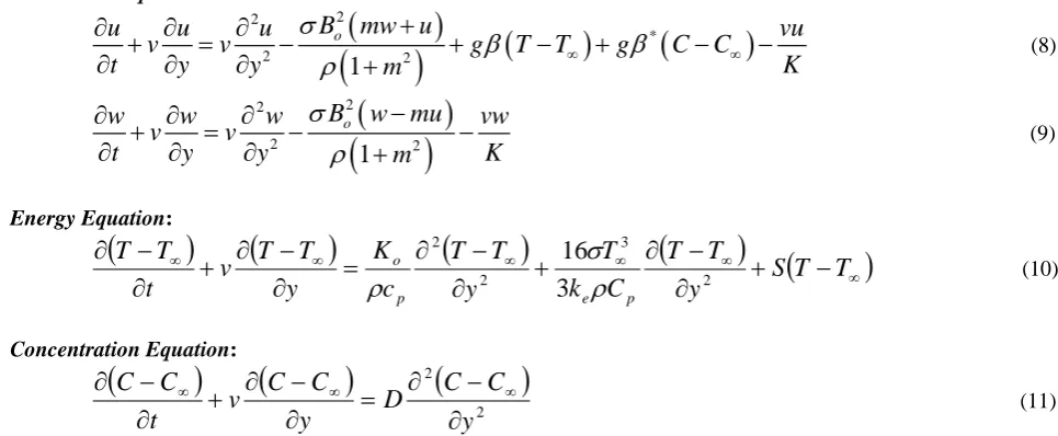
e. The equations of motion, energy and concentration governing the flow under the usual Boussinesq’s approximation areMomentum Equation:
(
)
(
)
(
)
(
)
2 2 * 2 21
oB
mw u
u
u
u
vu
v
v
g
T
T
g
C
C
t
y
y
m
K
σ
β
β
ρ
∞ ∞+
∂
+
∂
=
∂
−
+
−
+
−
−
∂
∂
∂
+
(8)(
)
(
)
2 2 2 21
oB
w mu
w
w
w
vw
v
v
t
y
y
m
K
σ
ρ
−
∂
+
∂
=
∂
−
−
∂
∂
∂
+
(9)Energy Equation:
(
)
(
)
(
)
(
) (
)
∞ ∞ ∞ ∞ ∞ ∞+
−
∂
−
∂
+
∂
−
∂
=
∂
−
∂
+
∂
−
∂
T
T
S
y
T
T
C
k
T
y
T
T
c
K
y
T
T
v
t
T
T
p e p o 2 3 2 23
16
ρ
σ
ρ
(10)Concentration Equation:
(
)
(
)
(
)
2 2y
C
C
D
y
C
C
v
t
C
C
∂
−
∂
=
∂
−
∂
+
∂
−
∂
∞ ∞ ∞ (11)where g is the acceleration due to gravity, T is the temperature of the fluid within the boundary layer, C is the species concentration, ρ is the fluid density of boundary layer, ν is the kinematic viscosity, Ko is the thermal conductivity, cpis
the specific heat at constant pressure, D is the chemical and molecular diffusivity, K is the permeability of porous medium and S is the source sink parameter. In equation (10) the viscous dissipation and ohmic dissipation are neglected and in equation (11), the term due to chemical reaction is assumed to be absent.
Now using
v
=
−
V
o,
T
( )
y
,
t
−
T
∞=
θ
( )
y
,
t
andC
( )
y
,
t
−
C
∞=
C
*( )
y
,
t
Subject to the initial and boundary conditions:
We introduce the following non-dimensional parameters as follows
=
=
=
=
=
=
=
=
=
=
=
=
=
=
∗ ∞ 2 o ' 2 2 ' 3 3 3 2 ' 3 * * ' ' ' ' 2 'V
,
4
,
4
,
4
,
4
4
,
Pr
,
,
,
,
,
4
,
Sv
S
v
K
V
K
V
b
vg
Gm
V
a
vg
Gr
V
v
B
M
D
v
Sc
T
k
k
R
K
c
v
b
C
C
a
V
w
w
V
u
u
v
T
V
t
v
y
V
o o o o o e o p o o o oβ
β
ρ
σ
σ
ρ
θ
θ
η
(13)Equations (8) to (11) are transformed to their corresponding non-dimensional forms (dropping the dashes) as
(
) ( ) ( )
K
u
C
Gm
Gr
u
mw
m
M
u
u
t
u
+
+
+
−
+
−
∂
∂
=
∂
∂
−
∂
∂
θ
η
η
2 22
1
4
4
(14)(
)
K
w
mu
w
m
M
w
w
t
w
−
−
+
−
∂
∂
=
∂
∂
−
∂
∂
2 2 21
4
4
η
η
(15)θ
η
θ
η
θ
θ
S
R
t
∂
+
∂
+
=
∂
∂
−
∂
∂
2 23
4
1
Pr
4
4
(16) 2 24
4
η
η
∂
∂
=
∂
∂
−
∂
∂
C
Sc
C
t
C
(17) where Vo is some reference velocity, Gr is the Grashof number for heat transfer, Gm is the Grashof number for masstransfer, Pr is the Prandtl number, R is the Radiation Parameter, Sc is the Schmidt number, M is the Hartmann number and S is the source/sink parameter.
Dropping dashes, the modified boundary conditions become,
( )
( ) ( )
( )
( )
( )
( )
( )
( )
( )
( )
( )
0 :
,
,
,
,
0
0,
0,
0,
0,
,
0,
0
0 :
,
0,
,
0,
,
0,
,
0
i t i t
t
u
t
w
t
t
C
t
u
t
w
t
t
e
C
t
e
a
t
t
u
t
w
t
t
C
t
as
ω ω
η
η
θ η
η
η
θ
η
θ
η
≤
=
=
=
= ∀
=
=
=
=
=
>
∞
→
∞
→
∞
→
∞
→
→ ∞
(18)
3. METHOD OF SOLUTION
By applying Galerkin finite element method for equation (14) over the element (e),
η
j≤
η
≤
η
k is:0
4
4
( )) ( ) ( 2 ) ( 2
=
+
−
∂
∂
+
∂
∂
−
∂
∂
∫
η
η
η
η ηd
P
Bu
u
t
u
u
N
k j e e e e T (19) Where P =(
Gr
)
θ
ij+
(
Gm
)
C
ij−
Amw
ij;
1
;
K
A
B
=
+
21
m
M
A
+
=
Integrating the first term in equation (19) by parts one obtains
0
4
4
4
( )) ( ) ( ) ( ) ( ) ( ) ( ) (
=
−
+
∂
∂
−
∂
∂
+
∂
∂
∂
∂
−
∂
∂
∫
η
η
η
η
η
η η η ηd
P
Bu
u
t
u
N
u
N
u
N
k j k j e e e T e e T e e T e (20)Neglecting the first term in equation (20), one gets:
0
4
4
( )) ( ) ( ) ( ) ( ) (
=
−
+
∂
∂
−
∂
∂
+
∂
∂
∂
∂
∫
η
η
η
η
η ηd
P
Bu
u
t
u
N
u
N
k j e e e T e e T eLet
u
(e)=
N
(e)φ
(e) be the linear piecewise approximation solution over the element (e)where
N
(e)=
[
N
jN
k]
,
φ
(e)=
[
u
ju
k]
T andj k j k j k k j
N
N
η
η
η
η
η
η
η
η
−
−
=
−
−
=
,
are the basis functions. Onevertical porous plate immersed in porous medium with heat source/sink / IJMA- 7(9), Sept.-2016.
η
η
η
η η η η η η d u u N N N N N N N N d u u N N N N N N N N d u u N N N N N N N N k j k j k j k j k k k j k j j j k j k k k j k j j j k j k k k j k j j j∫
∫
∫
− + • • ' ' ' ' ' ' ' ' ' ' ' ' 4 4 ‘η
η
η η η ηd
N
N
P
d
u
u
N
N
N
N
N
N
N
N
B
k j k j k j k j k k k j k j j j∫
∫
=
+
Simplifying we get
2 ( )
( )
1
1
2
1
1 1
2
1
1
4
1
4
1
1
6
1
2
2
1 1
6
1
2
2
1
j
j j j
e e
k k k
k
u
u
u
B
u
P
l
u
u
u
l
u
• •
−
−
+
−
+
=
−
−
Where k j e
l
()=
η −
η
& prime and dot denotes differentiation w.r.t ‘η’ and time ‘t’ respectively. Assembling theelement equations for two consecutive elements
η
i−1≤
η
≤
η
i andη
i≤
η
≤
η
i+1 following is obtained:2
1
1 1 1
( ) ( )
1 1 1
1
1
1
0
2 1 0
1
1
0
2 1 0
1
4
1
4
1
2
1
1 4 1
1
0
1
1 4 1
2
6
2
6
2
0
1
1
0 1 2
0
1 1
0 1 2
1
i
i i i
i
i e i i
e
i i i
i
u
u
u
u
B
P
u
u
u
u
l
l
u
u
u
u
• − − − − • • + + + +
−
−
−
−
+
−
−
+
=
−
−
(21)Now put row corresponding to the node ‘i’ to zero, from equation (21) the difference schemes with
l
(e)=
h
is:
[
]
[
] [
]
2 1 1 1 1 ( ) 1 1 1 1
( )
4
1
4
2
4
4
6
i i i2
6
i i i e i i i i i
e
B
u
u
u
u
u
u
u
u
u
u
u
P
l
l
• • • − + − + − + − +
−
+
−
+
+
+
−
−
+
+
+
+
=
(22)Applying the trapezoidal rule, following system of equations in Crank-Nicholson method are obtained:
* 1 6 5 1 4 1 1 3 1 2 1 1
1
u
A
u
A
u
A
u
A
u
A
u
P
A
in−++
in++
in++=
in−+
in+
in++
(23)Applying the same procedure to the equations (15), (16) and (17) then the following equations are obtained:
* 1 6 5 1 4 1 1 3 1 2 1 1
1
w
B
w
B
w
B
w
B
w
B
w
Q
B
inn i n i n i n i n
i
+
+
=
−+
+
++
+ + +
+
− (24)
n i n i n i n i n i n
i
G
G
G
G
G
G
4 1 5 6 11 1 3 1 2 1 1
1 − +
+ + +
+
−
+
θ
+
θ
=
θ
+
θ
+
θ
θ
(25) n i n i n i n i n i ni
J
C
J
C
J
C
J
C
J
C
C
J
1 4 1 5 6 11 3 1 2 1 1
1 − +
+ + +
+
−
+
+
=
+
+
(26)Where A1 = 2 + 12rh + Bk – 24r; A2 = 4Bk + 48r + 8; A3 = 2 + Bk - 12rh - 24r;
A4 = 2 - Bk - 12rh + 24r; A5 = 8 – 4Bk – 48r; A6 = 2 - Bk + 12rh + 24r;
B1 = 2 + 12rh + Bk – 24r; B2 = 4Bk + 48r + 8; B3 = 2 + Bk - 12rh - 24r;
B4 = 2 - Bk - 12rh + 24r; B5 = 8 – 4Bk – 48r; B6 = 2 - Bk + 12rh + 24r;
;
12
)
(
12
)
(
12
* j i j i ji
k
Gm
C
kAmw
Gr
k
P
=
θ
+
−
Q
*=
12
kAmu
ij;
G1 = 2(Pr) + 3rh(Pr) – 6rF – S(Pr)k; G2 = 8(Pr) + 12rF - 4S(Pr)k;
G3 = 2(Pr) – 3rh(Pr) - 6rF - S(Pr)k; G4 = 2(Pr) - 3rh(Pr) + 6rF + S(Pr)k;
G5 = 8(Pr) – 12rF + 4S(Pr)k; G6 = 2(Pr) + 3rh(Pr) + 6rF + S(Pr)k;
Where
+
=
R
F
3
4
1
4
J1 = 2(Sc) + 12rh(Sc)- 24r; J2 = 8(Sc) + 48r; J3 = 2(Sc) - 12rh(Sc)- 24r;
J4 = 2(Sc) - 12rh(Sc)+ 24r; J5 = 8(Sc) - 48r; J6 = 2(Sc) + 12rh(Sc)+ 24r;
Here r= 2
h
k
and h, k are mesh sizes along y- direction and time-direction respectively. Index ‘i’ refers to space and ‘j’
refers to the time. In the equations (23), (24), (25) and (26) taking i = 1(1) n and using boundary conditions (18), then the following system of equations are obtained:
4
)
1
(
1
=
=
B
i
X
A
i i i (27)where
A
i's are matrices of order n andX
i,'
i
The solutions of above system of equations are obtained by using Thomas algorithm for primary velocity, secondary velocity, temperature and concentration. Also, numerical solutions for these equations are obtained by C - programme. In order to prove the convergence and stability of Galerkin finite element method, the same C - programme was run with smaller values of h and k and no significant change was observed in the values of u, w, θ and C. Hence the Galerkin finite element method is stable and convergent.
4. SHEAR STRESS
The shearing stress at the wall along x-axis is given by
0 1
=
∂ ∂ =
y y u τ
And shearing stress at the wall along z-axis is given by
0 2
=
∂ ∂ =
y y w τ
5. RESULTS AND DISCUSSION
Some numerical calculations have been carried out for the non-dimensional velocity (u), temperature (T), concentration (C), skin-friction coefficient
(
τ
)
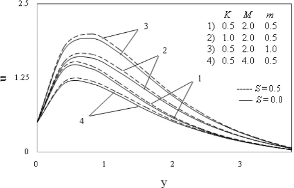
. The effects of material parameters such as Grashof number Gr, Modified Grashof number Gm, Permeability parameter K, Prandtl number Pr, Schmidt number Sc, Radiation parameter R, Hartmann number M and Hall parameter m are studied in the presence and absence of heat source and sink. Figure 1 and 7 show the variation of velocity profiles of main flow ‘u’ and cross flow ‘w’ respectively in the presence and absence of heat source for various values of K, m, M and for fixed values of Pr = 0.71 (air), Sc = 0.22 (Hydrogen), Gr = 1.0, Gm = 1.0, R = 1.0 and t = 1.0. From these graphs, it is observed that the primary velocity ‘u’ increases with the increase of Permeability parameter K and decreases with increase of Hartmann number M while it increases with the increase of Hall parameter m. Further, it is seen that the cross flow velocity ‘w’ increases with increase of Hall parameter m and Permeability parameter K and decreases with increase of M. From the figures, it is also observed that in the presence of heat source (S > 0), the main and cross flow velocities ‘u’ and ‘w’ increase, when compared with that the absence of heat source (S = 0).Figures 2 and 8 show the effect of heat sink on main and cross flow velocity components ‘u’ and ‘w’ respectively for various values of K, m and M. From these figures it is clear that in the presence of heat sink (S < 0), the main and cross flow velocities ‘u’ and ‘w’ decrease when compared with that in the absence of heat sink.
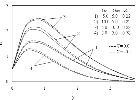
In the absence and presence of heat source, the variation of main and cross flow velocity profiles for various values Gr,
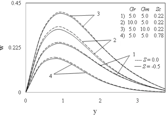
Gm and Sc are shown in the figures 3 and 9 respectively. From this it is observed that the primary and secondary velocities increases with the increase of Grashof number Gr and Modified Grashof number Gm, but they decreases with the increase of Schmidt number Sc. Further, it is observed that both the primary and secondary velocities of the fluid increase in the presence of heat source.
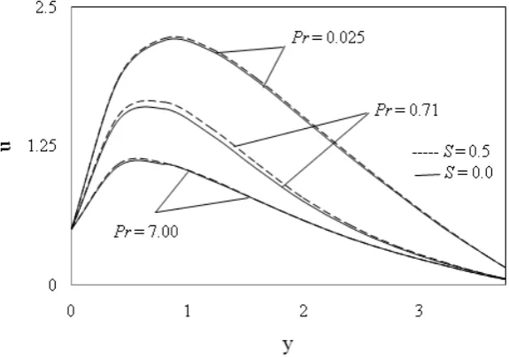
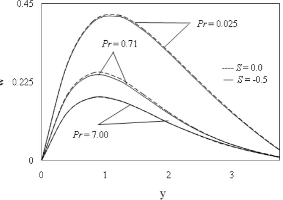
The effect of Prandtl number Pr on the main and cross flow velocities in the absence and presence of heat source are shown in the figures 5 and 11 respectively. From this it is observed that the primary and secondary velocities decreases with the increase of Prandtl number Pr. Further, it is observed that both the primary and secondary velocities of the fluid increase in the presence of heat source when compared with the absence of heat sink
In the presence of heat sink, the nature of the velocity profiles of main and cross flow are shown in the figures 4 and 10 respectively for various values of Gr, Gm and Sc. It is evident from these figures that in the presence of heat sink the primary and secondary velocities of the fluids decreases when compared with that in the absence of magnetic field.
In the presence of heat sink, the effect of Prandtl number on the velocity profiles of main and cross flow are shown in the figures 6 and 12 respectively. It is evident from these figures that in the presence of heat sink the primary and secondary velocities of the fluids decreases when compared with that in the absence of magnetic field.
Figures (13) and (14) shows the main flow velocity and temperature profiles for different values of the thermal
Radiation parameter R.
,
4
* ∞3=
T
kk
R
eσ
and this defines the ratio of thermal conduction contribution relative to thethermal radiation. For radiative heat transfer dominance in the boundary layer regime, R → 0. For finite values of R there will be a simultaneous presence of thermal conduction and radiative transfer contribution. For R=1 both modes will contribute equally. For R → ∞, in equation (16), the term 4/3R → 0 and the energy conservation equation reduces to the convectional unsteady conduction-convection equation with heat absorption. i.e.
θ
η
θ
η
θ
θ
S
t ∂ +
∂ = ∂ ∂ − ∂ ∂
2 2
vertical porous plate immersed in porous medium with heat source/sink / IJMA- 7(9), Sept.-2016.
An increase in R from 0 (total thermal radiation dominance) through 0.5, 5.0, 20.0 to 30.0, causes a significant decrease in main flow velocity with distance into the boundary layer i.e. decelerates the main flow. Velocities in all cases ascend from the plate surface, peak close to the wall and then decay smoothly to zero in the free stream. Thermal radiation flux therefore has a de-stabilizing effect on the transient flow regime. This is important in polymeric and other industrial flow processes since it shows that the presence of thermal radiation while decreasing temperature, will affect flow control from the plate surface into the boundary layer regime. As expected, temperature values are also significantly reduced with an increase in R as there is a progressive decrease in thermal radiation contribution accompanying this. All profiles are monotonic decay from the wall to the free stream.
Figure 15 shows the effect of heat source/sink on temperature profiles for various values Pr. It is evident that the fluid temperature increases in the presence of heat source while it decreases in the presence of heat sink. Further, it is also observed that an increase in Prandtl number Pr leads to decrease in the temperature field. The thermal boundary layer thickness is greater for fluids with small Prandtl number. The reason is that smaller values of Pr are equivalent to increasing thermal conductivity and therefore heat is able to diffuse away from the heated surface more rapidly than for higher values of Pr. Moreover, the effect of radiation is to decrease the rate of energy transport to the fluid and accordingly decrease the fluid temperature.
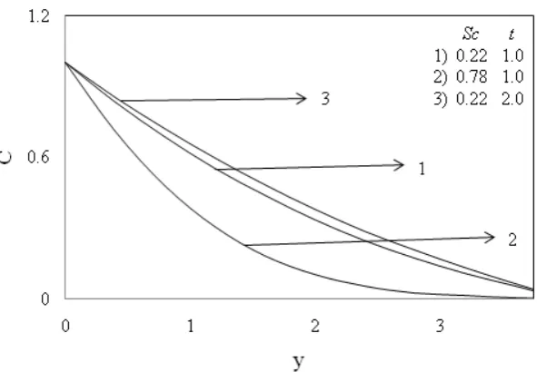
The variation of concentration for different values of Sc like Hydrogen (Sc = 0.22), Ammonia (Sc= 0.78) and t is shown in the figure 16. It is clear from this figure that the concentration of fluid decreases with the increase of Schmidt number Sc while it increases as time t increases. This is consistent with the fact that the increase of Scmeans a decrease of molecular diffusivity (D) that result in decrease of concentration boundary layer. Hence the concentration of species is higher for smaller value of Scand lower for larger value of Sc.
Table (1) shows the variation of shearing stress in the presence and absence of heat source and sink and for different values Gr, Gm, Pr, Sc, m, M, K, R and t. From this table it is concluded that
1) Shearing stress τ1 and τ2 increase as the value of Gr, Gm, m increase, but they decrease with the increase of Pr,
Sc. It is also noted from the table that the magnitude of shearing stress τ1 and τ2increases in the presence of
heat source while in the presence of heat sink this behavior is found just reverse.
2) In the presence of heat source the magnitude shearing stress τ1 and τ2 increase, but they decrease in the absence
of heat source.
3) Further, it is observed that the magnitude shearing stress τ1 and τ2 decrease in the presence of heat sink while
in the absence of heat sink they increase.
Figure 2: Effect of heat sink on velocity component ‘u’
Figure 3: Effect of heat source on velocity component ‘u’
vertical porous plate immersed in porous medium with heat source/sink / IJMA- 7(9), Sept.-2016.
Figure 5: Effect of heat source on velocity component ‘u’
Figure 6: Effect of heat sink on velocity component ‘u’
Figure 8: Effect of heat sink on secondary velocity component ‘w’
Figure 9: Effect of heat source on secondary velocity component ‘w’
vertical porous plate immersed in porous medium with heat source/sink / IJMA- 7(9), Sept.-2016.
Figure 11: Effect of heat source on secondary velocity component ‘w’
Figure 12: Effect of heat sink on secondary velocity component ‘w’
Figure 14: Effect of Thermal Radiation Parameter ‘R’ on Temperature profiles ‘θ’.
Figure 15: Effect of Prandtl number on temperature component ‘θ’
vertical porous plate immersed in porous medium with heat source/sink / IJMA- 7(9), Sept.-2016.
6. CONCLUSIONS
The problem “Hall Effect on MHD mixed convective flow of a viscous incompressible fluid past a vertical porous plate immersed in porous medium with heat source/sink.” is studied. The dimensionless equations are solved by using Galerkin finite element method. The effects different parameters like Gr, Gm, Pr, Sc, M, m, K and S on velocity, temperature and concentration are studied. The study concludes the following results.
1) It is observed that both the primary (u) and secondary (w) velocities of the fluid increases in the presence of heat source and decreases in presence of sink.
2) The fluid Temperature increases in the presence of heat source while it decreases in the presence of heat sink. 3) The velocity and temperature profiles decreases with increase of thermal radiation parameter.
4) The Concentration of the fluid decreases with the increasing Schmidt number Sc.
5) The primary velocity (u) and secondary velocity (w) are decreases with the increasing of Prandtl number.
Table-1: Variation of shearing stress τ1and τ2 for different values of Gr, Gm, Pr, Sc, m, M, K, R and t when S = 0.0, 0.5
and -0.5.
τ1 τ2
Gr Gm Pr Sc m M K R t S = -0.5 S = 0.0 S = 0.5 S = -0.5 S = 0.0 S = 0.5
1.0 1.0 0.71 0.22 0.5 2.0 0.5 1.0 1.0 2.27903 2.34579 2.42366 0.30281 0.31051 0.31936 3.0 1.0 0.71 0.22 0.5 2.0 0.5 1.0 1.0 4.24772 4.47244 4.73489 0.53612 0.56227 0.59228 1.0 3.0 0.71 0.22 0.5 2.0 0.5 1.0 1.0 5.25315 5.32806 5.41555 0.72202 0.73073 0.74074 1.0 1.0 7.00 0.22 0.5 2.0 0.5 1.0 1.0 1.60607 1.62832 1.65537 0.21801 0.21962 0.22156 1.0 1.0 0.71 0.28 0.5 2.0 0.5 1.0 1.0 1.52753 1.54978 1.57683 0.20056 0.20219 0.20412 1.0 1.0 0.71 0.22 1.5 2.0 0.5 1.0 1.0 2.79211 2.87841 2.97896 0.49405 0.50704 0.52188 1.0 1.0 0.71 0.22 0.5 4.0 0.5 1.0 1.0 1.82758 1.88693 1.95653 0.38927 0.40094 0.41443 1.0 1.0 0.71 0.22 0.5 2.0 1.0 1.0 1.0 2.37522 2.45013 2.53761 0.31453 0.32325 0.33326 1.0 1.0 0.71 0.22 0.5 2.0 0.5 2.0 1.0 1.4263 1.4473 1.5241 0.6148 0.6471 0.7182 1.0 1.0 0.71 0.22 0.5 2.0 0.5 1.0 0.5 1.66938 1.69858 1.73019 0.13547 0.13714 0.13947
ACKNOWLEDGMENT
This research is carried out under the UGC Minor research Project (MRP-4618/14(SERO/UGC)). The Authors are thankful to UGC for financial support.
REFERENCES
1. J. A. Shercliff, A Text Book of Magnetohydrodynamics, Pergamon Press, London, 1965.
2. V. C. A. Ferraro, C. Plumption, An Introduction to Magneto Fluid Mechanics, Clarandon Press, Oxford, 1966. 3. K. P. Crammer, S. L. Pai, Magneto-fluid Dynamic for Engineers and Applied Physicist, Mc-Graw Hill book
Co., New York, 1973.
4. Hayat, T., Mustafa M., and Pop, I., Heat and mass transfer for Soret and Dufour effects on mixed convection boundary layer flow over a stretching vertical surface in a porous medium filled with a viscoelastic fluid.
Comm. Nonlinear Sci Numer Simulat. 15, 1183-1196, 2010.
5. M. A. Hossain, D. A. S. Rees, Combined heat and mass transfer in natural convection flow from a vertical wavy surface, Acta Mech., 136, 133–141, 1999.
6. Chien-Hsin-Chen, Combined heat and mass transfer in MHD free convection from a vertical surface with Ohmic heating and viscous dissipation, Int. J. Eng. Science, 42, 699–713, 2004.
7. Hossain M.A. and Takhar H.S. (1996), Radiation effects on mixed convection along a vertical plate with uniform surface temperature –Heat and Mass Transfer, 31, 243- 248.
8. Raptis A. and Perdikis C. (1999), Radiation and free convection flow past a moving Plate-International Journal of Applied Mechanics and Engineering, 4, 817-821.
9. E. M. Aboeldahab, E. M. E. Elbarbary, Hall current effect on magnetohydrodynamics free convection flow past a semi-infinite vertical plate with mass transfer, Int. J. Eng. Science, 39, 1641–1652, 2001.
10. N. Datta, R. N. Jana, Oscillatory magnetohydrodynamic flow past a flat plate will Hall effects, J. Phys. Soc. Japan, 40, 1469, 1976.
11. M. Acharya, G. C. Dash, L. P. Singh, Hall effect with simultaneous thermal and mass diffusion on unsteady hydromagnetic flow near an accelerated vertical plate, Indian J. of Physics B, 75B(1), 168, 2001.
13. S. Ostrach, Laminar natural convection flow and heat transfer of fluid with and without heat source in channel with wall temperature, NACA TN, 2863, 1952.
14. Ibid, Combined natural and forced convection laminar flow and heat transfer of fluid with and without heat sources in channels with linearly varying wall temperatures, NACA TN 3141, 1954.
15. Ibid, Unstable convection in vertical channels with heating from below, including effects of heat source and frictional heating, NACA TN 3458, 1958.
16. A. A. Raptis, Free convection and mass transfer effects on the flow past an infinite moving vertical porous plate with constant suction and heat source, Astrophy. Space Sci., 86, 43, 1982.
17. Atul Kumar Singh, MHD free convection and mass transfer flow with heat source and thermal diffusion, J. of Energy, Heat and Mass Transfer, 23, 227–249, 2001.
18. T.G.Cowling, Magneto-Hydrodynamics, Wiley Interscience, New York, 1957.
Source of support: University Grant Commission, India. Conflict of interest: None Declared