Available online throug
ISSN 2229 – 5046
EFFECT OF CHEMICAL REACTION AND RADIATION ABSORPTION
ON THE UNSTEADY CONVECTIVE HEAT AND MASS TRANSFER FLOW
OF A VISCOUS FLUID IN A VERTICAL WAVY CHANNEL
WITH OSCILLATORY FLUX AND HEAT SOURCES
Dr. G. Viswanatha Reddy
1*& S. Venkatarami Reddy
21
Associate Professor, Department of Mathematic, S. V. University, Tirupathi, A. P, India
2
Department of Mathematics, S. V. University, Anantapur, A.P, India
(Received on: 17-12-12; Revised & Accepted on: 05-02-13)
ABSTRACT
W
e analyse the effect of chemical reaction and radiation absorption on the transient convective heat and mass transfer flow of a viscous, electrically conducting fluid in a vertical wavy channel with oscillatory flux. The equations governing the flow, heat and mass transfer are solved by employing a regular perturbation technique with the slope δ as a perturbation parameter. The velocity, temperature, concentration, the rate of heat and mass transfer are analysed for different parametric values.Keywords: Heat and Mass transfer, Chemical reaction parameter, Radiation absorption, Heat sources.
1. INTRODUCTION
Coupled heat and mass transfer phenomenon in porous media is gaining attention due to its interesting applications. The flow phenomenon is relatively complex rather than that of the pure thermal convection process. Underground spreading chemical wastes and other pollutants, grain storage ,evaporation cooling and solidification are the few other application areas where the combined thermo-solutal natural convection in porous media are observed .Combined heat and mass transfer by free convection under boundary layer approximations has been studied by Bejan and Khair(2),Lai and Kulacki(9) and Murthy and Singh(11).Coupled heat and mass transfer by mixed convection in Darcian fluid-saturated porous media has been analysed by Lai(8).The free convection heat and mass transfer in a porous enclosure has been studied recently by Angirasa et al(1). The combined effects of thermal and mass diffusion in channel flows has been studied in recent times by a few authors, notably Nelson and Wood(14,15), Lee at al(10) and others(23,25).
In recent years, energy and material saving considerations have prompted an expansion of the efforts at producing efficient heat exchanger equipment through augmentation of heat transfer. It has been established (5a) that channels with diverging – converging geometries augment the transportation of heat transfer and momentum. As the fluid flows through a tortuous path viz., the dilated – constricted geometry, there will be more intimate contact between them. The flow takes place both axially (primary) and transversely (secondary) with the secondary velocity being towards the axis in the fluid bulk rather than confining within a thin layer as in straight channels. Hence it is advantageous to go for converging – diverging geometries for improving the design of heat transfer equipment. Vajravelu and Nayfeh (23a) have investigated the influence of the wall waviness on friction and pressure drop of the generated coquette flow. Vajravelu and Sastry (24) have analysed the free convection heat transfer in a viscous, incompressible fluid confined between long vertical wavy walls in the presence of constant heat source. Later Vajravelu and Debnath (25) have extended this study to convective flow in a vertical wavy channel in four different geometrical configurations. This problem has been extended to the case of wavy walls by McMichael and Deutsch (109), Deshikachar et al (49), Rao et al (17a) and Sree Ramachandra Murthy (20a). Hyan Goo Kwon et al (7a) have analyzed that the Flow and heat/mass transfer in a wavy duct with various corrugation angles in two dimensional flow regimes. Mahdy et al (79) have studied the mixed convection heat and mass transfer on a vertical wavy plate embedded in a saturated porous media (PST/PSE). Comini et al (3a) have analyzed the Convective heat and mass transfer in wavy finned-tube exchangers. Jer-Huan Jang et al (58) have analyzed that the Mixed convection heat and mass transfer along a vertical wavy surface.
In many chemical engineering processes, there does occur the chemical reaction between a foreign mass and the fluid in which the plate is moving. These processes take place in numerous industrial applications viz., polymer production,
Corresponding author: Dr. G. Viswanatha Reddy1*
manufacturing of ceramics or glassware and food processing .Das et al (5) have studied the effects of mass transfer on flow past an impulsively started infinite vertical plate with constant heat flux and chemical reaction. Muthukumara-swamy (13) has studied the effects of reaction on a long surface with suction. Recently Gnaneswar(6) has studied radiation and mass transfer on an unsteady two-dimensional laminar convective boundary layer flow of a viscous incompressible chemically reacting fluid along a semi-infinite vertical plate with suction by taking into account the effects of viscous dissipation.
The present trend in the field of chemical reaction analysis is to give a mathematical model for the system to predict the reactor performance. A large amount of research work has been reported in this field. In particular the study of heat and mass transfer with chemical reaction is of considerable importance in chemical and hydrometallurgical industries. Chemical reaction can be codified as either heterogeneous or homogeneous processes. This depends on whether they occur at an interface or as a single phase volume reaction. Frequently the transformations proceed in a moving fluid, a situation encountered in a number of technological fields. A common area of interest in the field of aerodynamics is the analysis of thermal boundary layer problems for two dimensional steady and incompressible laminar flow passing a wedge. Simulataneous heat and mass transfer from different geometrics embedded in a porous media has many engineering and geophysical application such as geothermal reservoirs, drying of porous solids thermal insulation, enhanced oil recovery, packed-bed catalytic reactors, cooling of nuclear reactors, and under ground energy transport. A very significant area of research in radiative heat transfer, at the present time is the numerical simulation of combined radiation and convection/conduction transport processes. The effort has arisen largely due to the need to optimize industrial system such as furnaces, ovens and boilers and the interest in our environment and in no conventional energy sources, such as the use of salt-gradient solar ponds for energy collection and storage. In particular, natural convection induced by the simultaneous action of buoyancy forces resulting from thermal and mass diffusion is of considerable interest in nature and in many industrial application such as geophysics, oceanography, drying process, solidification of binary alloy and chemical engineering. Kandaswamy et al (9a) have discussed the Effects of chemical reaction, heat and mass transfer on boundary layer flow over a porous wedge with heat radiation in the presence of suction or injection.
Recently Madhusudan Reddy (10b) has analysed the effect of chemical reaction on double diffusive heat transfer flow of a viscous fluid in a wavy channel.
In this paper we discuss the effect of chemical reaction and radiation absorption on unsteady free connective heat and mass transfer flow in a vertical wavy channel. The unsteadiness in the flow is due to the oscillatory flux in the flow region. The coupled equations governing the flow, heat and mass transfer have been solved by using a perturbation technique with the slope δ as the perturbation parameter. The expression for the velocity, the temperature, the concentration, and the rate of heat and mass transfer are derived and are analysed for different variations of the governing parameters G, M, β, k Q.
2. FORMULATION OF THE PROBLEM
We consider the effect of chemical reaction on the unsteady motion of viscous, incompressible fluid through a porous medium in a vertical channel bounded by wavy walls. The
thermal buoyancy in the flow field is created by an oscillatory flux in the fluid region. The walls are maintained at constant temperature and concentration. The Boussinesq approximation is used so that the density variation will be considered only in the buoyancy force. The viscous and Darcy dissipations are neglected in comparison with heat by conduction and convection in the energy equation. Also the Kinematic viscosity ν, the thermal conducting k are treated as constants. We choose a rectangular Cartesian system 0(x, y) with x-axis in the vertical direction and y-axis normal to the walls. The
walls of the channel are at
(
)
L
x
Lf
y
=
±
δ
The equations governing the unsteady flow, heat and mass transfer are
Equation of continuity
0
=
∂
∂
+
∂
∂
y
v
x
u
(2.1)
Configuration of the Problem
x
T = T1 T=T2
C = C1 C=C2
H0 y
y = - Lf(δ x/L) y = + Lf(δ x/L)
Equation of linear momentum
2 2
2 2
2 2
(
)
e e o
u
u
u
p
u
u
u
v
g
H u
t
x
y
x
x
y
ρ
∂
+
∂
+
∂
= −
∂
+
µ
∂
+
∂
−
ρ
−
σµ
∂
∂
∂
∂
∂
∂
(2.2)2 2
2 2 e
v
v
v
p
v
v
u
v
t
x
y
y
x
y
ρ
∂
+
∂
+
∂
= −
∂
+
µ
∂
+
∂
∂
∂
∂
∂
∂
∂
(2.3)Equation of Energy:
2 2
' 1
2 2
(
)
(
)
e p e e
T
T
T
T
T
C
u
v
Q T
T
Q C
C
t
x
y
x
y
ρ
∂
+
∂
+
∂
=
λ
∂
+
∂
−
−
+
−
∂
∂
∂
∂
∂
(2.4)Equation of diffusion
2 2
1 2 2 1
(
e)
C
C
C
C
C
u
v
D
k C
C
t
x
y
x
y
∂
∂
∂
∂
∂
+
+
=
+
−
−
∂
∂
∂
∂
∂
(2.5)Equation of state
)
(
)
(
e e ee
e
=
−
T
−
T
−
C
−
C
−
ρ
βρ
β
∗ρ
ρ
(2.6)where
ρ
e is the density of the fluid in the equilibrium state, Te, Ce are the temperature and concentration in the equilibrium state,(u,v)are the velocity components along O(x,y) directions, p is the pressure, T, C are the temperature and Concentration in the flow region,ρis the density of the fluid,µ is the constant coefficient of viscosity, Cp is the specific heat at constant pressure,λis the coefficient of thermal conductivity ,k is the permeability of the porous medium ,β is the coefficient of thermal expansion, Q is the strength of the constant internal heat source,σ is the electrical conductivity ,µe is the magnetic permeability,β
∗ is the volumetric expansion with mass fraction coefficient D1, is the molecular diffusivity and k1 is the chemical reaction coefficient.The flow is maintained by an oscillatory volume flux for which a characteristic velocity is defined as
∫
−=
+
f L
f L t
i
dy
u
L
e
k
q
(
1
ω)
1
. (2.7)The boundary conditions for the velocity and temperature fields are
u = 0, v = 0, T=T1 , C=C1 on
x
y
Lf
L
δ
= −
2 2
,
0
,
0
v
T
T
C
C
u
=
=
=
=
ony
Lf
x
L
δ
= +
(2.8)In view of the continuity equation we define the stream function ψ as
u = -ψy , v = ψx (2.9)
Eliminating pressure p from equations (2.2) & (2.3) and using the equations governing the flow in terms of ψ are
2
2 2 2 4 2 2
0 0 2
[(
)
t x(
)
y y(
) ]
xg T
(
T
)
yg C
(
C
)
y(
eH
o)
y
ψ
ψ
ψ
ψ
ψ
ψ
ν ψ β
β
∗σµ
∂
∇
+
∇
−
∇
= ∇
−
−
=
−
−
∂
(2.10)2
(
)
e p o
T
T
T
C
T
Q T
T
t
y
x
x
y
ψ
ψ
ρ
∂
−
∂ ∂
+
∂ ∂
= ∇ −
λ
−
∂
∂ ∂
∂ ∂
(2.11)2
1
(
o)
C
C
C
D
C
k C
C
t
y
x
x
y
ψ
ψ
∂
−
∂ ∂
+
∂ ∂
= ∇
−
−
∂
∂ ∂
∂ ∂
Introducing the non-dimensional variables in (2 .8) & (2.9) as 2 1 2 2 1 2
,
,
/
,
,
/
,
/
c
C
C
C
C
T
T
T
T
t
t
L
y
y
L
x
x
−
−
=
′
−
−
=
Ψ
=
Ψ′
=
′
=
′
=
′
ω
ν
θ
(2.13)
The governing equations in the non-dimensional form ( after dropping the dashes ) are
2 2
2 2 4 2
2
( ,
)
(
)
(
)
( , )
t y y
G
R
NC
M
x y
R
y
ψ
ψ
ψ
γ
ψ
ψ
θ
∇
−
∂
∇
= ∇
+
+
−
∂
∂
∂
(2.14)2 2
1
P
Q C
t
y
x
x
y
θ
ψ θ
ψ θ
γ
θ αθ
∂
∂ ∂
∂ ∂
−
+
= ∇ −
+
∂
∂ ∂
∂ ∂
(2.15)2
C
C
C
2Sc
C
KC
t
y
x
x
y
ψ
ψ
γ
∂
∂ ∂
∂ ∂
−
+
= ∇
−
∂
∂ ∂
∂ ∂
(2.16)where
ν
UL
R
=
(Reynolds number) 23
ν
β
g
T
L
G
=
∆
e (Grashof number)1
k
c
pµ
=
Ρ
(Prandtl number),2 2 2 2 2
ν
σµ
H
L
M
=
e o(Hartman Number)
1
Sc
D
ν
=
(Schmidt Number)2
QL
α
λ
=
(Heat source parameter)1 2 1
D
L
K
K
=
(Chemical reaction parameter)ν
ω
γ
2=
L
2(Wormsely Number) p e
C
D
L
C
C
Q
Q
1 2 ' 1 1)
(
−
=
(Radiation absorption parameter) 22 2 2 2
y
x
∂
∂
+
∂
∂
=
∇
The corresponding boundary conditions are
1
)
(
)
(
+
f
−
ψ
−
f
=
ψ
f
aty
y
x
∂
=
=
±
∂
=
∂
∂
ψ
ψ
η
0
,
0
(2.17)f
y
on
C
y
x
f
y
on
C
y
x
=
=
=
−
=
=
=
0
,
0
)
,
(
1
,
1
)
,
(
θ
θ
0
0
,
0
=
=
∂
∂
=
∂
∂
y
at
y
C
y
θ
(2.18)The value of ψ on the boundary assumes the constant volumetric flow in consistant with the hyphothesis (2.7). Also the wall temperature varies in the axial direction in accordance with the prescribed arbitrary function t .
3. METHOD OF SOLUTION
The main aim of the analysis is to discuss the perturbations created over a combined free and forced convection flow due to traveling thermal wave imposed on the boundaries. The perturbation analysis is carried out by assuming that the aspect ratio
δ
to be small.Introduce the transformation such that
x
x
x
x
∂
∂
=
∂
∂
Then
(
)
O
(
1
)
x
O
x
∂
≈
∂
→
≈
∂
∂
δ
For small values of δ<<1, the flow develops slowly with axial gradient of order δ
And hence we take
O
(
1
)
x
≈
∂
∂
Using the above transformation the equations (2.15-2.17) reduces to
2 2
2 2 1 4 2
1 1 2
( ,
)
(
)
(
)
( , )
t y y
G
R
NC
M
x y
R
y
ψ
ψ
ψ
δ
γ
∇
ψ
+
∂
∇
= ∇
ψ
−
θ
+
−
∂
∂
∂
(3.1)2 2
1 1
P
Q
t
y
x
x
y
θ
ψ θ
ψ θ
δ
γ
∂
−
∂ ∂
+
∂ ∂
= ∇ −
θ αθ
+
∂
∂ ∂
∂ ∂
(3.2)2 2
1
C
C
C
Sc
C
KC
t
y
x
x
y
ψ
ψ
δ
γ
∂
−
∂ ∂
+
∂ ∂
= ∇
−
∂
∂ ∂
∂ ∂
(3.3)where 2 2 2 2 2 2 1
y
x
∂
∂
+
∂
∂
=
∇
δ
Introducing the transformation
)
(
x
f
y
=
η
the equations(3.1-3.3) reduces to
2 3 2
2 2 4 2 2
2
( ,
)
(
)
(
) (
)
( , )
tF
Gf
Rf
F
F
NC
M f
x
R
η ηψ
ψ
ψ
δ
γ
ψ
ψ
θ
η
η
∂
∂
+
=
−
+
−
∂
∂
(3.4)
2 2 2 2
1
P
f
F
f
Q f C
t
x
x
θ
ψ θ
ψ θ
δ
γ
θ α θ
η
η
∂
−
∂ ∂
−
∂ ∂
=
−
+
∂
∂ ∂
∂ ∂
(3.5)2
C
C
C
2Sc
f
F C
KC
t
x
x
ψ
ψ
δ
γ
η
η
∂
−
∂ ∂
−
∂ ∂
=
−
∂
∂ ∂
∂ ∂
(3.6)where 2 2 2 2 2 2
η
δ
∂
∂
+
∂
∂
=
x
F
We adopt the perturbation scheme and write
.
....
...
))
,
,
(
.
)
,
,
(
(
)
,
,
(
)
,
,
(
)
,
,
(
x
η
t
=
ψ
0x
η
t
+
ke
itψ
0x
η
t
+
δ
ψ
1x
η
t
+
ke
itψ
1x
η
t
+
ψ
.
....
...
))
,
,
(
.
)
,
,
(
(
)
,
,
(
)
,
,
(
)
,
,
(
x
η
t
=
θ
0x
η
t
+
ke
itθ
0x
η
t
+
δ
θ
1x
η
t
+
ke
itθ
1x
η
t
+
θ
.
....
...
))
,
,
(
.
)
,
,
(
(
)
,
,
(
)
,
,
(
)
,
,
(
x
t
=
C
0x
t
+
ke
C
0x
t
+
C
1x
t
+
ke
C
1x
t
+
C
η
η
itφ
η
δ
η
itη
On substituting (3.1) in (3.4) - (3.6) and separating the like powers of δ the equations and respective conditions to the zeroth order are
3 2 2
0,
(
1)
0, y(
0, 0,)
Gf
M f
NC
R
ηηηη ηη η η
ψ
−
ψ
= +
θ
+
(3.8)
0 1 0 2
,
(
f
)
Q
C
o
−
α
θ
=
−
θ
ηη (3.9)0
)
(
2 0,
−
KScf
C
=
C
oηη (3.10)with
ψ0(+1)-Ψ0(-1) = 1,
ψ0, η = 0, ψ0 , x =0 at η = ±1 (3.11)
0
0
1,
1
1
0,
0
1
o
o
C
on
C
on
θ
η
θ
η
=
=
= −
=
=
=
(3.12)
0 1 0 2 2 ,
0
−
(
iP
γ
f
)
θ
=
−
Q
C
θ
µη (3.13)0
)
(
2 2,
0
−
KSc
f
C
o=
C
ηηγ
(3.14)3 2 2 2
0,
((
1)
)
0,(
0, 0.)
Gf
M
i
f
NC
R
ηηηη ηη η η
ψ
−
+
γ
ψ
= −
θ
+
(3.15)( 1)
0,
( 1)
0
o
C
oθ
± =
± =
0
)
1
(
,
0
)
1
(
1
)
1
(
)
1
(
+
−
o−
=
o,±
=
o,x±
=
o
ψ
ψ
ψ
ψ
η (3.16)The first order equations are
3 2 2
1,
(
1)
1,(
1, 1,) (
)(
0, 0,x 0,x 0,)
Gf
M f
N C
Rf
R
ηηηη ηη η η η ηη ηηη
ψ
−
ψ
= −
θ
+
+
ψ ψ
−
ψ ψ
(3.17)1 1 ,
0 , , 0 1
2
)
(
)
(
)
(
,
1
−
α
f
θ
=
PRf
ψ
xθ
o−
ψ
θ
ox−
Q
C
θ
ηη η η (3.18))
(
)
(
)
(
2 1 0, , 0,,
1
KScf
C
Scf
xC
oC
oxC
y
ψ
ηψ
ηηη
−
=
−
(3.19)3 2 2 2
1,
((
1)
)
1,(
1, 1,) (
)(
0, 0,x 0, 0,x 0,x 0, 0,x 0,)
Gf
M
i
f
N C
Rf
R
ηηηη ηη η η η ηη η ηη ηηη ηηη
ψ
−
+
γ
ψ
= −
θ
+
+
ψ ψ
+
ψ ψ
−
ψ ψ
−
ψ ψ
(3.20)1,
2 2
1 0, , 0, 0, , 0, 1 1
((
iP
)
f
)
(
PRf
) (
o x o x x o x o)
Q C
ηη η η η η
θ
−
γ
+
α
θ
=
ψ θ
+
ψ θ
−
ψ θ
−
ψ θ
−
(3.21)1,
2 2
1 0, , 0, 0, , 0,
((
)
)
(
) (
o x o x x o x o)
C
ηη−
K
+
i
γ
Scf
C
=
Scf
ψ
ηC
+
ψ
ηC
−
ψ
C
η−
ψ
C
η (3.22)with
ψ1(+1) -ψ1(-1 ) = 0
θ1(±1) = 0 C1(±1) = 0
1
( 1)
0
C
1( 1)
0
θ ± =
± =
0
)
1
(
,
0
)
1
(
1
)
1
(
)
1
(
1 1, 1,1
+
−
ψ
−
=
ψ
±
=
ψ
x±
=
ψ
η (3.24)4. SOLUTION OF THE PROBLEM
Solving the equations (3.2)- (3.13) subject to the relevant boundary conditions we obtain
1 1 0 1 1
(
)
(
)
0.5
(
)
(
)
Ch
Sh
C
Ch
Sh
β η
β η
β
β
=
−
)
(
)
(
)
(
1 14 1 15 16 113
η
η
η
η
ψ
o=
a
Ch
M
+
a
Sh
M
+
a
+
a
+
f
)
(
)
(
)
(
)
(
)
(
9 1 10 1 11 2 12 21
η
a
Sh
β
η
a
Ch
β
η
a
Sh
β
η
a
Ch
β
η
f
=
+
+
+
0
0=
C
0
0=
θ
18 17 1 160
=
a
Sh
(
M
η
)
+
a
η
+
a
ψ
)
(
)
(
)
(
2 93 2 292
1
a
Ch
β
η
a
Sh
β
η
f
η
C
=
+
+
2 91 1 2 90 1 2 89 1 86 1 85 5 84 1 87 77 76 1 88 78 75 9 82 74 8 81 73 9 72 8 83 71 7 70 6 69 7 80 68 6 79 67 2 ) ( ) ( ) ( ) ( ) ( ) 2 ( )) ( ( ) 2 ( )) ( ( ) ( ) ( ) ( ) ( ) ( ) ( ) ( ) ( ) ( ) ( ) ( ) ( ) ( ) (
η
η
β
η
η
β
η
η
β
η
η
β
η
η
β
η
η
β
η
η
β
η
η
β
η
η
β
η
η
β
η
β
η
η
β
η
β
η
β
η
η
β
η
η
a Sh a Ch a Ch a Sh a Sh a Ch a a a Sh a a a Ch a a Ch a a Sh a Sh a a Ch a Sh a Ch a a Ch a a f − + + + + + + + + + + + + + + + + + + + + + + + + + + =)
(
)
(
)
(
1 93 1 392
1
β
η
β
η
η
θ
=
b
Ch
+
b
Sh
+
f
3 1 10 2 11 3 10 4 11 5 9 6 9
7 8 8 8 9 7 10 7 11 6 12 6
13 1 14 1 15 2 16 2 17 2 18 2
( )
(
)
(
)
(
)
(
)
(
)
(
)
(
)
(
)
(
)
(
)
(
)
(
)
(2
)
(2
)
(
)
(
)
(2
)
(2
f
d Ch
d Ch
d Sh
d Sh
d Ch
d Sh
d Ch
d Sh
d Ch
d Sh
d Ch
d Sh
d Sh
d Ch
d Ch
d Sh
d Sh
d Ch
η
β η
β η
β η
β η
β η
β η
β η
β η
β η
β η
β η
β η
β η
β η
β η
β η
β η
β
=
+
+
+
+
+
+
+
+
+
+
+
+
+
+
+
+
+
2 2 3
19 1 20 1 21 1 22 1 23 1
3
24 1 25 1 26 2 27 1 28 2
29 2 30 2 31 6 32 7 34 7
35 8
)
(
)
(
)
(
)
(
)
(
)
(
)
(2
)
(2
)
(2
)
(
)
(
)
(
)
(
)
(
)
(
)
(
d
Ch
d
S
hd
Ch
d
S
hd
Ch
d
Sh
d
Sh
d
Sh
d
Ch
d
Ch
d
Sh
d
Ch
d
Ch
d
Ch
d
Ch
d
Sh
η
η
β η
η
β η
η
β η
η
β η
η
β η
η
β η
η
β η
η
β η
η
β η
η
β η
η
β η
η
β η
η
β η
η
β η
η
β η
η
β
+
+
+
+
+
+
+
+
+
+
+
+
+
+
+
+
+
36 9 37 6 38 7 39 102
40 11 41 11 42 10 43 11 43 44
)
(
)
(
)
(
)
(
)
(
)
(
)
(
)
(
)
d
Sh
d
Sh
d
Sh
d
Sh
d
Sh
d
Sh
d
Ch
d
Ch
d
d
η
η
β η
η
β η
η
β η
η
β η
η
β η
η
β η
η
β η
η
β η
η
+
+
+
+
+
+
+
+
−
−
)
(
)
(
)
(
1 4 1 43 2 1
1
η
η
η
η
ψ
=
p
+
p
+
p
Ch
M
+
p
Sh
M
+
f
4 1 1 2 1 3 2 4 2 5 6
6 7 7 8 8 9 9 10 10 11
11 6 12 7 13 8 14 9 15 10
2
16 11 17 1 97 1
( )
(
)
(
)
(
)
(
)
(
)
(
)
(
)
(
)
(
)
(
)
(
)
(
)
(
)
(
)
(
)
(
)
(2
)
(
f
g Sh
g Ch
g Sh
g Ch
g Sh
g Sh
g Sh
g Sh
g Sh
g Sh
g Ch
g Ch
g Ch
g Ch
g Ch
g Ch
g Ch
E
Sh M
η
β η
β η
β η
β η
β η
β η
β η
β η
β η
β η
β η
β η
β η
β η
β η
β η
β η
η
η
=
+
+
+
+
+
+
+
+
+
+
+
+
+
+
+
+
+
298 1
2
99 1 104 1 105 1 106 1
)
(
)
(
)
(2
)
(2
)
(2
)
E
Ch M
E
Sh M
E
Sh
M
E
Sh
M
E Ch
M
η
η
η
η
η
η
η
η
η
+
21 12 22 13 23 14 24 15 25 12
3 2
26 13 27 14 28 15 57 1 29 1
3 2
30 1 72 1 31 1 32 1
(
)
(
)
(
)
(
)
(
)
(
)
(
)
(
)
(
)
(
...
(
(
)
(
)
(
)
a Sh
a Sh
a Sh
a Sh
a Ch
a Ch
a Ch
a Ch
E
Sh
g
Sh
g
Sh
E
Ch
g
Ch
g
Ch
β η
β η
β η
β η
β η
β η
β η
β η
η
β η
η
β η
η
β η
η
β η
η
β η
η
β η
+
+
+
+
+
+
+
+
+
+
+
+
+
+
+
5. NUSSELT NUMBER and SHERWOOD NUMBER
)
(
)
(
τ
y=−1=
d
6+
Ecd
7+
δ
d
8+
O
δ
2The local rate of heat transfer coefficient (Nusselt number Nu) on the walls has been calculated using the formula
1
)
(
1
± =
∂
∂
−
=
θ
ηθ
θ
y
Nu
w m
where
∫
−
=
1
1
5
.
0
θ
η
θ
md
and the corresponding expressions are
9 11 8 10
1 1
(
)
(
)
(
)
, (
)
(
m(
))
(
m1)
d
d
d
d
N u
N u
Sin x
t
η η
δ
δ
θ
γ
θ
=+ =−
+
+
=
=
−
+
−
, whereθ
m=
d
14+
δ
d
15The local rate of mass transfer coefficient( Sherwood Number Sh) on the walls has been calculated using the formula
1
1
m w y
C
Sh
C
C
y
=±
∂
=
−
∂
where=
−∫
1
1
5
.
0
C
dy
C
mand the corresponding expressions are
4 6 5 7
1 1
(
)
(
)
(
)
(
)
(
m)
(
m1)
d
d
d
d
Sh
Sh
C
C
η η
δ
δ
=+ =−
+
+
=
=
−
,where
C
m=
d
12+
δ
d
13 , whered
1.
d
2,...
...
...,
d
14 are constants.6. DISCUSSION OF THE RESULTS
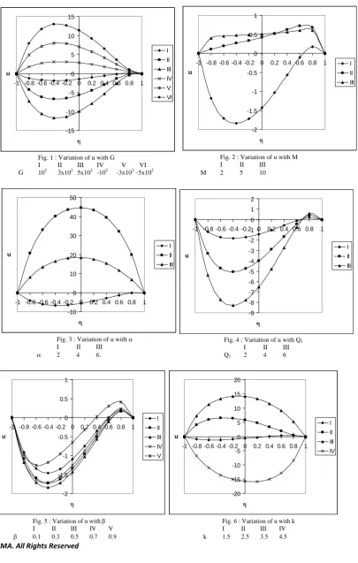
In this analysis, we investigate the effect of chemical reaction and radiation absorption on unsteady convective heat and mass transfer flow of a viscous electrically conducting fluid in a vertical wavy channel in the presence of heat generating sources. The axial velocity is shown in figure 1 – 11 for different values of G, M, Q1,β, k. The actual axial flow is in the vertically downward direction i.e. u < 0 is actual flow and u > 0 is a reversal flow.
Fig 1 represents the variation of u with Grashof number G. It is found that u exhibits a reversal flow in entire fluid region and the region of reversal flow enlarges with increase in |G| with maximum attained at η = -0.4. The magnitude of u enhances with increase in |G|.
Higher the Lorentz force lesser |u| in the flow region (fig.2).
An increase in the strength of the heat source enhances |u| in fluid region. Also for α≥ 4, u exhibits a reversal flow in the entire flow region (fig.3).
An increase in the radiation absorption parameter Q1 results in an enhancement in |u| with reversal flow in the vicinity of η = 1 (fig.4).
The influence of the surface geometry on u is shown in fig.5. It is found that higher the dilation of the channel walls, larger |u| for β≤ 0.5 and larger for |β|≥0.7.
The variation of u with chemical reaction parameter k shows that the axial velocity enhances with increase in k (fig.6).
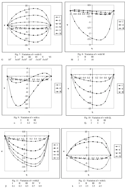
The secondary velocity (v) which is due to the wall waviness of the channel is shown in figs 7-12.
From fig.7 that for G>0, v is towards the midregion and is towards the boundary for G<0. |v| enhances with increase in |G| with maximum attained at η = 0.4.
The variation of v with heat source parameter α shows that the magnitude of v enhances remarkably with increase in α
≤ 4 and depreciates with higher α≥ 6. (fig.9).
An increase in Q1 leads to an enhancement in |v| (fig.10).
From fig.11 we find that higher the dilation of the channel walls larger |v| in the flow region.
The variation of v with chemical reaction parameter k shows that |v| enhances with increase in k ≤ 3.5 and depreciates with higher k ≥ 4.5 (fig.12).
-15 -10 -5 0 5 10 15
-1 -0.8 -0.6 -0.4 -0.2 0 0.2 0.4 0.6 0.8 1
η u
I II III IV V VI
Fig. 1 : Variation of u with G
I II III IV V VI
G 102 3x10² 5x10² -102 -3x10² -5x10²
-2 -1.5 -1 -0.5 0 0.5 1
-1 -0.8 -0.6 -0.4 -0.2 0 0.2 0.4 0.6 0.8 1
η u
I II III
Fig. 2 : Variation of u with M
I II III
M 2 5 10
-10 0 10 20 30 40 50
-1 -0.8 -0.6 -0.4 -0.2 0 0.2 0.4 0.6 0.8 1
η u
I II III
Fig. 3 : Variation of u with α
I II III
α 2 4 6.
-9 -8 -7 -6 -5 -4 -3 -2 -1 0 1 2
-1 -0.8 -0.6 -0.4 -0.2 0 0.2 0.4 0.6 0.8 1
η u
I II III
Fig. 4 : Variation of u with Q1
I II III
Q1 2 4 6
-2 -1.5 -1 -0.5 0 0.5 1
-1 -0.8 -0.6 -0.4 -0.2 0 0.2 0.4 0.6 0.8 1
η u
I II III IV V
-20 -15 -10 -5 0 5 10 15 20
-1 -0.8 -0.6 -0.4 -0.2 0 0.2 0.4 0.6 0.8 1
η u
I II III IV
Fig. 5 : Variation of u with β Fig. 6 : Variation of u with k
I II III IV V I II III IV
-15 -10 -5 0 5 10 15
-1 -0.8 -0.6 -0.4 -0.2 0 0.2 0.4 0.6 0.8 1
η v
I II III IV V VI
Fig. 7 : Variation of v with G
I II III IV V VI
G 102 3x10² 5x10² -102 -3x10² -5x10²
-3 -2.5 -2 -1.5 -1 -0.5 0 0.5
-1 -0.8 -0.6 -0.4 -0.2 0 0.2 0.4 0.6 0.8 1
η v
I II III
Fig. 8 : Variation of v with M
I II III
M 2 5 10
-16 -14 -12 -10 -8 -6 -4 -2 0 2 4
-1 -0.8 -0.6 -0.4 -0.2 0 0.2 0.4 0.6 0.8 1
η v
I II III
Fig. 9 : Variation of v with α
I II III
α 2 4.2 6.2
-12 -10 -8 -6 -4 -2 0 2
-1 -0.8 -0.6 -0.4 -0.2 0 0.2 0.4 0.6 0.8 1
η v
I II III
Fig. 10 : Variation of v with Q1
I II III
Q1 2 4 6
-4 -3.5 -3 -2.5 -2 -1.5 -1 -0.5 0 0.5
-1 -0.8 -0.6 -0.4 -0.2 0 0.2 0.4 0.6 0.8 1
η v
I II III IV V
-10 -5 0 5 10 15
-1 -0.8 -0.6 -0.4 -0.2 0 0.2 0.4 0.6 0.8 1
η v
I II III IV
Fig. 11 : Variation of v with β Fig. 12 : Variation of v with k
I II III IV V I II III IV
β 0.1 0.3 0.5 0.7 0.9 k 1.5 2.5 3.5 4.5
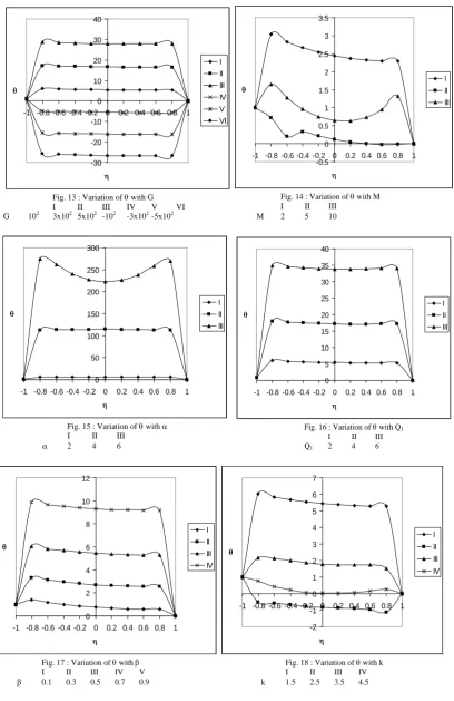
The non-dimensional temperature (θ) is shown in figures 13-18 for different parametric values. We follow the convention that the non-dimensional temperature is positive or negative according as the actual temperature is greater (or) lesser than T2. Fig. 13 represents θ with Grashof number G. It is found the actual temperature enhances with G>0 and depreciates with G<0.
The actual temperature depreciates with M (fig. 14).
From fig 16 we notice that the actual temperature enhances with increase in the radiation absorption parameter Q1.
The influence of the wall waviness is shown in (fig.17). It is found that higher the dilation of the channel walls larger the actual temperature.
An increase in the chemical reaction parameter k≤2.5 leads to a depreciation in the actual temperature, enhances at k = 3.5 and again depreciates with higher k≥4.5 (fig.18).
-30 -20 -10 0 10 20 30 40
-1 -0.8 -0.6 -0.4 -0.2 0 0.2 0.4 0.6 0.8 1
η θ
I II III IV V VI
Fig. 13 : Variation of θ with G
I II III IV V VI
G 102 3x10² 5x10² -102 -3x10² -5x10²
-0.5 0 0.5 1 1.5 2 2.5 3 3.5
-1 -0.8 -0.6 -0.4 -0.2 0 0.2 0.4 0.6 0.8 1
η θ
I II III
Fig. 14 : Variation of θ with M
I II III
M 2 5 10
0 50 100 150 200 250 300
-1 -0.8 -0.6 -0.4 -0.2 0 0.2 0.4 0.6 0.8 1
η θ
I II III
Fig. 15 : Variation of θ with α
I II III
α 2 4 6
0 5 10 15 20 25 30 35 40
-1 -0.8 -0.6 -0.4 -0.2 0 0.2 0.4 0.6 0.8 1
η θ
I II III
Fig. 16 : Variation of θ with Q1
I II III
Q1 2 4 6
0 2 4 6 8 10 12
-1 -0.8 -0.6 -0.4 -0.2 0 0.2 0.4 0.6 0.8 1
η θ
I II III IV
-2 -1 0 1 2 3 4 5 6 7
-1 -0.8 -0.6 -0.4 -0.2 0 0.2 0.4 0.6 0.8 1
η θ
I II III IV
Fig. 17 : Variation of θ with β Fig. 18 : Variation of θ with k
I II III IV V I II III IV
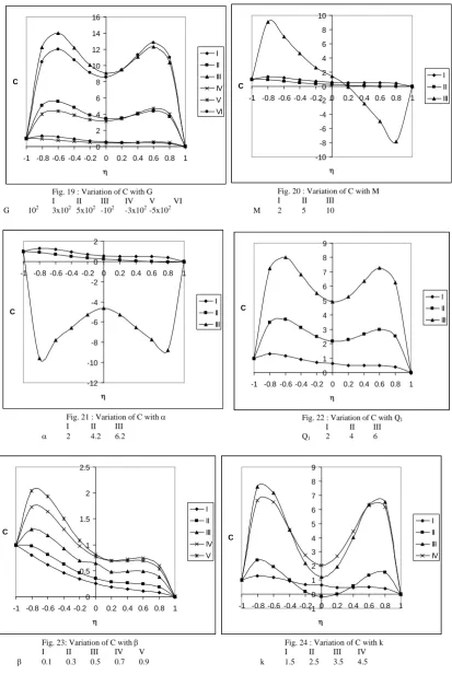
The non-dimensional concentration (C) is shown in figs 19-24 for different parametric values. Fig.19 represents the concentration C with Grashof number G. It is found that the actual concentration enhances with increase in |G| with maximum at η = 0.6.
0 2 4 6 8 10 12 14 16
-1 -0.8 -0.6 -0.4 -0.2 0 0.2 0.4 0.6 0.8 1
η C
I II III IV V VI
Fig. 19 : Variation of C with G
I II III IV V VI
G 102 3x10² 5x10² -102 -3x10² -5x10²
-10 -8 -6 -4 -2 0 2 4 6 8 10
-1 -0.8 -0.6 -0.4 -0.2 0 0.2 0.4 0.6 0.8 1
η C
I II III
Fig. 20 : Variation of C with M
I II III
M 2 5 10
-12 -10 -8 -6 -4 -2 0 2
-1 -0.8 -0.6 -0.4 -0.2 0 0.2 0.4 0.6 0.8 1
η C
I II III
Fig. 21 : Variation of C with α
I II III
α 2 4.2 6.2
0 1 2 3 4 5 6 7 8 9
-1 -0.8 -0.6 -0.4 -0.2 0 0.2 0.4 0.6 0.8 1
η C
I II III
Fig. 22 : Variation of C with Q1
I II III
Q1 2 4 6
0 0.5 1 1.5 2 2.5
-1 -0.8 -0.6 -0.4 -0.2 0 0.2 0.4 0.6 0.8 1
η C
I II III IV V
-1 0 1 2 3 4 5 6 7 8 9
-1 -0.8 -0.6 -0.4 -0.2 0 0.2 0.4 0.6 0.8 1
η C
I II III IV
Fig. 23: Variation of C with β Fig. 24 : Variation of C with k
I II III IV V I II III IV
β 0.1 0.3 0.5 0.7 0.9 k 1.5 2.5 3.5 4.5
The variation of C with Hartmann number M shows that higher the Lorentz force smaller the actual concentration and for further higher Lorentz force larger in the left half and smaller in the right half (fig.20).
An increase in Q1 enhances in the entire flow region (fig.22).
Higher the dilation of the channel walls larger the actual concentration in entire flow region (fig.23).
For k≤2.5, we find that the actual concentration enhances in the region, except in the region (-0.2, 0.2_ where it depreciates and for higher k≥3.5, it depreciates in the regions adjacent to η = ±1 and enhances in the central region (fig.24).
The rate of heat transfer (Nu) at η = ±1 is shown tables 1-2 for different values of G, Q1, k, β. It is found that the rate of heat transfer enhances at η = 1 and reduces at η = -1 with G>0 and for G<0, we notice an enhancement at both the walls. An increase in R enhances |Nu| at η=±1. The variation of Nu with chemical reaction parameter k shows that |Nu| enhances with k at η=±1. An increase in Q1 reduces it at η=+1 and enhances at η = -1. Moving along the axial direction the Nusselt number reduces at η=+1 and enhances at η= -1 for all G. Higher the dilation of the walls larger the magnitude of rate of heat transfer at both walls (tables 1&2).
The rate of mass transfer (Sh) at η± 1 is shown in tables 3 – 4 for different parametric values. An increase in G>0 enhances |Sh| at η=±1 while it enhances at η=+1 and reduces at η=-1 for G<0. An increase in the radiation absorption parameter Q1 enhances the rate of mass transfer at η=+1 and at η=-1, it reduces with Q1≤4 for G>0 and enhances for G<0 and for higher Q1≥6, it reduces for all G. An increase in k ≤1.5 enhance |Sh| and depreciates with higher k ≥ 2.5 in the heating case and cooling case a reversed effect is observed in the behaviour of |Sh| at η=+1. At η=-1 the rate of mass transfer depreciate increase in k for all G. Higher the dilation of the channel walls larger |Sh| at η = +1 and smaller |Sh| at η = -1. (tales 3 & 4).
Table-1
Nusselt number (Nu) at η = +1
G I II III IV V VI VII VIII
103 -0.01355 -0.15009 -0.2512 -0.04482 -0.0835 -0.08638 -0.05328 -0.05940 3x10³ -0.05273 -0.17771 -0.2715 -0.02960 -0.07830 -0.07833 0.01036 0.09965 5x10³ -0.08850 -0.17728 -0.2911 -0.01811 -0.07154 -0.07159 0.05678 0.21915 -103 0.04165 -0.06977 -0.0714 -0.06613 -0.09612 -0.09614 -1.17251 -0.36295 -3x10³ -0.31573 0.11382 -0.1192 -0.09837 -0.10823 -0.10823 -0.89185 6.60215 -5x10³ 0.02425 0.51517 0.5314 -0.15335 -0.12361 -0.12359 0.36967 0.14976
k 0.5 1.5 2.5 0.5 0.5 0.5 0.5 0.5
β 0.5 0.5 0.5 0.7 0.9 1.5 0.5 0.5
Q1 2 2 2 2 2 2 4 6
Table-2
Nusselt number (Nu) at η = -1
G I II III IV V VI VII VIII
103 0.14333 0.61643 0.71643 0.57149 0.64032 0.64034 0.41680 0.50759 3x10³ 0.03876 0.39136 0.41138 0.47128 0.56305 0.56310 0.32303 0.44518 5x10³ -0.02551 0.26869 0.36769 0.40397 0.50255 0.50261 0.29137 0.47656 -103 0.50148 1.05419 1.15324 0.73607 0.74243 0.74241 0.78730 1.01501 -3x10³ -0.66386 2.02311 2.25113 1.05548 0.88367 0.88356 -5.25261 -1.78571 -5x10³ -0.15408 4.92682 5.45236 1.93890 1.09187 1.09158 -0.60105 -0.66296
k 0.5 1.5 2.5 0.5 0.5 0.5 0.5 0.5
β 0.5 0.5 0.5 0.7 0.9 1.5 0.5 0.5
Q1 2 2 2 2 2 2 4 6
Table-3
Sherwood number (Sh) at η = +1
G I II III IV V VI VII VIII
103 -0.30188 0.85633 -0.52111 0.40905 0.51252 0.51257 1.06125 2.36756 3x10³ -0.59315 1.51080 0.55367 0.85223 0.96660 0.96666 2.65128 6.41349 5x10³ -1.16595 1.95975 0.56229 1.30990 1.42070 1.42075 4.77216 13.31212
-103 -0.27264 0.16688 -0.65218 -0.02066 0.05845 0.05847 -0.13264 -0.08798 -3x10³ -0.49281 -0.30296 0.10005 -0.43783 -0.39561 -0.39562 -1.01993 -1.53827 -5x10³ -0.95572 -0.46478 0.25704 -0.84331 -0.84966 -0.84971 -1.66209 -2.28564
k 0.5 1.5 2.5 0.5 0.5 0.5 0.5 0.5
β 0.5 0.5 0.5 0.7 0.9 1.5 0.5 0.5
Table-4
Sherwood number (Sh) at η = -1
G I II III IV VI VII VIII IX
103 -10.51477 -9.27785 -1.23367 -7.56091 -7.50540 -7.50545 -10.25605 -11.40274 3x10³ -14.33007 -15.05510 -2.36074 -8.36586 -8.54437 -8.54464 -9.56771 -8.12803 5x10³ -19.48473 1.49560 -2.49667 -9.10470 -9.58328 -9.58384 -7.99190 -3.36845 -103 -8.44286 -8.39664 -3.99941 -6.68520 -6.46636 -6.46625 -9.37967 -10.48924 -3x10³ -8.48669 -8.75085 -3.08048 -5.73381 -5.42726 -5.42705 -5.65396 2.82965 -5x10³ -10.92910 1.18119 -2.92544 -4.70151 -4.38809 -4.38786 3.60951 64.41862
k 0.5 1.5 2.5 0.5 0.5 0.5 0.5 0.5
β 0.5 0.5 0.5 0.7 0.9 1.5 0.5 0.5
Q1 2 2 2 2 2 2 4 6
7. REFERENCES
[1]. Angirasaa,D, Peterson,G.P and Pop, I :Combined heat and mass transfer by natural convection with opposing buoyancy effects in a fluid saturated porous medium, Int. J. Heat Mass Transfer,V.40, pp.2755-2773(1997). [2]. Bejan,A and Khair, K.R:Heat and Mass transfer by natural convection in a porous medium, Int. J. Heat Mass
transfrt,V.28,pp.908-918(1985).
[3]. Chamkha,A,J., Takhar, H.S and Soundalgekar, V.M :Chem. Engng. J., V.84, p.104 (2003).
[4]. Comini.G , C.Nonino and S.Savino(2002): Convective heat and mass transfer in wavy finned-tube exchangers, International journals of Numerical Methods for Heat and Fluid flow,v.12,i.6,p.735-755.
[5]. Cheng,P: Heat transfer in geothermal systems, Adv. Heat Transfer,V.14, pp.1-105(1978).
[6]. Deshikachar, K.S and Ramachandra Rao, A (1985). Effect of a magnetic field on the flow and blood oxygenation in channel of variable cross-section, Int. J. Engg Sci, V.23 pp 1121.
[7]. Das,U.N, Deka,R.K and Soundalgekar, V.M:Forsching in Inge, V.80, p.284 (1994).
[8]. Gagan S (1985). Proceedings of natural heat and mass transfer conference, Visakhapatnam, India. [9]. Gnaneswar reddy: Acta Ciencia Indica, V.34M,No,21, p.639(2008).
[10]. Hussain,M.A and Takhar, H,S: Heat and Mass transfer,V.31,p.243(1996).
[11]. Hyan Goo Kwon, Sang Dong Hwang, Hyung Hee Cho (2008): Flow and heat/mass transfer in a wavy duct with various corrugation angles in two dimensional flow regimes, Heat and Mass Transfer, v.45, p.157-165.
[12]. Lai,F.C :Cpupled heat and mass transfer by mixed convection from a vertical plate in a saturated porous medium., Int. Commn. heat mass transfer, V.18, pp.93-106 (1971).
[13]. Lai,F.C and Kulacki,F.A : Coupled heat and mass transfer by natural convection from vertical surfaces in porous medium., Int. J. Heat Mass Transfer, V.34, pp.1189-1194(1991).
[14]. Kandaswamy .P,Abd.Wahid B.Md.Raj, azme B. Khamis(2006): Effects of chemical reaction, heat and mass transfer on boundary layer flow over a porous wedge with heat radiation in the presence of suction or injection, Theoret. Appl. Mech., V.33.No.2, pp.123-148.
[15]. Lee,T.S,Parikh, P.G,Archivos,A and Bershader,D: Int. J. Heat Mass Transfer, V, 25,pp. 499-522(1982). [16]. McMichael, M and Deutsch, S (1984). Phy, Fluids, V.27, p 110.
[17]. Madhusadana Reddy, Y: Mixed convective heat and mass transfer through a porous medium in channels with radiation effect, Ph.D. thesis, S. K. University, Anantapur, India (2010).
[18]. Murthy,P.V.S.N and Singh,P: Heat and Mass transfer by natural convection in a Non-Darcy porous medium,Acta Mech,V.26,pp.567(1990).
[19]. Muthukumaraswamy,R and Ganesan,P: Int. J. Appl. Mech and Engng., V.44, p.104 (2003). [20]. Muthukumaraswamy,R:Acta Mechnica,V.155, p.65(2002).
[21]. Nelson,D.J and Wood,B.D: Combined heat and mass transfer by natural convection between vertical plates with uniform flux boundary conditions, Heat transfer,V.4,pp.1587-1952(1986).
[22]. Nelson,D.J and Wood,B.D: Combined heat and mass transfer by natural convection between vertical plates ,Int.J., Heat Mass transfer,V.82,pp.1789-1792(1989).
[23]. Prakash,J and Ogulu: Ind. J. Pure and Applied Maths,V.44,P.805(2006).
[24]. Prasad,V, Kulacku,F.A and Keyhani,M: Natural convection in a porous medium, J. Fluid Mech.,V.150,pp.89-119(1985).
[25]. Prasada Rao, D.R.V, Krishna, D.V and Debnath, L (1983). Free convection in Hydromagnetic flows in a vertical wavy channel, Int. Engg. Sci, V.21, No.9, pp. 1025-1039.
[26]. Raptis,A and Takhar,H,.S :Heat and Mass transfer,V.31,p.243(1996).
[27]. Raptis, A.A and Perdikis, C (1999). Radiation and free convection flow past a moving plate, Appl. Mech. Eng, Vol.4, pp 817-821.
[28]. Soundalgekar,V.M and Takhar, H.S : Modelling measurement and comtrol, B.51, p.31, (1993).
[29]. Sree Ramachandra Murthy, A (1992). Buoyancy induced hydromagnetic flows through a porous medium – A study, Ph.D thesis, S. K. University, Anantapur, India.
[32]. Sudha Mathew: Hydro magnetic mixed convective heat and mass transfer through a porous medium in a vertical channel with thermo-diffusion effect. Ph.D thesis, S,K. University, Anantapur, India(2009).
[33]. Trevison, D.V and Bejan,A: Combined heat and mass transfer by natural convection in vertical enclosure,Trans.ASME,V.109,pp.104-111(1987).
[34]. Vajravelu K and Ali Neyfeh (1981): Influence of wall waviness on friction and pressure drop in channels, Int. J. Maths and Math. Sc., V.4, pp.805-818.
[35]. Vajravelu, K and Sastry, K.S. (1978): Heat transfer in a viscous incompressible fluid confined between a long vertical wavy wall and a parallel flat wall, J. Fluid Mech. V.86, No.2, p.365.
[36]. Vajravelu, K and Debnath, L: Non-linear study of convective heat transfer and fluid flows induced by traveling thermal waves, Acta Mech. V.59, pp 233-249.
[37]. Wei-Mon Yan: Combined buoyancy effects of thermal and mass diffusion on laminar forced convection in horizontal rectangular ducts, Int, J, Heat Mass transfer, V.39, pp.1479-1488(1996).