Volume 42 (2011)
Proceedings of the
4th International Workshop on
Multi-Paradigm Modeling
(MPM 2010)
Using an Alternative Trace for QVT
Vincent Aranega, Anne Etien and Jean-Luc Dekeyser
12 pages
Guest Editors: Vasco Amaral, Hans Vangheluwe, C ´ecile Hardebolle, Lazlo Lengyel Managing Editors: Tiziana Margaria, Julia Padberg, Gabriele Taentzer
Using an Alternative Trace for QVT
Vincent Aranega1, Anne Etien2and Jean-Luc Dekeyser3
1[email protected] 2[email protected] 3[email protected]
LIFL - UMR CNRS 8022, INRIA, University of Lille1, Lille, France
Abstract: Model transformations are the core of the MDE methodology. They can
be expressed using various languages. One of them is QVT, the OMG standard for transformation languages. QVT also provides a traceability mechanism. In general, a trace can be used for many purposes. In this paper, we show the limitations of the trace provided by QVT through different scenarios. Furthermore, based on the QVT language elements, we highlight model transformation concepts that would require consideration.
We also propose an alternative trace that takes into account these concepts. It allows us to gather information not provided by the QVT trace and thus fully performs the scenarios. The proposed trace is language independent and can be used without perturbing the QVT transformation execution or the trace generation/exploitation by the engine.
Keywords: MDE, QVT, Traceability, Model Transformation
1
Introduction
The Model Driven Engineering methodology (MDE) sets the models, metamodels and transfor-mations as first class citizens in the software development process. It relies on different standards, one of which is Query/View/Transformation (QVT) [Obj07], dedicated to model transforma-tions. The QVT standard describes the syntax and the semantics of three different sub-languages for transforming models. The Relations language is declarative, the Core language is fully im-perative and the Operational Mapping language is hybrid. Each of these language differently conceives transformations and adopts its own rule-based syntax. Nevertheless, they all produce almost the same trace.
In the context of model transformations, the trace links the input elements which were useful to create the output elements. The trace can be used for many different purposes, such as impact analysis (i.e., to identify the effect of changing one artifact on related artifacts), code regeneration (i.e., to automatically regenerate previously generated code that is related to a design artifact), visualization, flexible process modeling [PDK+
The QVT standard describes a trace which is recorded all along the transformation execution. This trace can be serialized at the end of the transformation execution in order to be post-mortem inspected. Nevertheless, its main purpose is to support the object resolution mechanism, indis-pensable to perform the transformation. The trace provided by QVT is thus mainly internally used by the engine and is not well adapted to the purposes previously identified.
In this paper, we show in various scenarios that the basic information required by most ac-tivities based on trace exploitation are not provided by the QVT trace. These observations con-cretely rely on the QVTO [Bor07] implementation of the QVT standard Operational Mapping language. We thus present a language-independent alternative to the QVT trace that is dedicated to the previously cited activities and provides the required information.
Section 2introduces a case study and four scenarios requiring trace information. Section3 shows, by applying the case study with the QVT trace that critical information is missing. From these limitations, in section4we propose an alternative. Section5corresponds to the application of the case study using our alternative trace. Finally, related works are presented in section6 whereas conclusions are drawn in section7.
2
Case Study
The case study introduced in this section is the main thread of the paper. It refers to the “UML to Marte” transformation context. After briefly explaining the purpose of the transformation and in-troducing the handled metamodel, we present the transformation written in the QVT Operational
Mapping language.
2.1 The UML to Marte Transformation
The “UML to Marte” transformation is very classic not because of the manipulated domains, but because it establishes a bridge between the UML world and the business world. Concretely, the input metamodel is UML enhanced with the Marte profile [OMG08], and the output metamodel is the Marte metamodel. The Marte profile is an OMG standard dedicated to the design and the analysis of real time embedded systems. This transformation is relevant, because it is complex enough to not be reduced to a one-to-one concept mapping. Moreover, the transformation is not too complicated to understand, even for non-business experts.
2.2 Input/Output Metamodels of the Transformation
The Marte profile, input of the transformation is rich in concepts. We focus on an excerpt, with-out detailing all the concepts. This excerpt presented in Figure1(a)contains three main concepts:
Allocate, Distribute and Tiler. The stereotypes Allocate and Distribute extend the Abstraction
UML element. In the same way, Tiler extends the Connector UML element. The three stereo-types own several tagged values adding information to the original UML elements. These tagged values are typed using datatypes defined in the profile, such as IntegerVector. Semantics details of these stereotypes/tagged values are out the scope of this paper.
<<stereotype>>
Allocate
+ kind: AllocationKind + nature: AllocationNature
(uml)
Abstraction
<<stereotype>>
Distribute
+ patternShape: ShapeSpecification + repetitionSpace: ShapeSpecification + fromTiler: TilerSpecification + toTiler: TilerSpecification
(uml)
Connector
<<stereotype>>
LinkTopology
<<stereotype>>
Tiler
+ origin: IntegerVector + paving: IntegerMatrix + fitting: IntegerMatrix + tiler: TilerSpecification
(a) Marte Profile Excerpt (b) Marte Metamodel Excerpt
Figure 1: Input and output metamodels
metamodel of the transformation, Figure 1(b) only gathers the elements relative to those pre-sented in Figure1(a).
As usual in such a transformation from a profile to the corresponding metamodel, concepts with the same semantics are found in the input and the output. Thus, Tiler and Distribute are designed in the Marte metamodel as specific entities. However, in the Marte metamodel, origin is considered as compositional relationship upon the IntegerVector element. The other relationships in the metamodel excerpt are designed using the same way.
2.3 The UML to Marte Transformation Expressed in QVTO
The “UML to Marte” transformation is quite huge: 1400 lines of QVTO code split into 98 rules. Only pieces of code relative to the elements previously presented are reproduced here. The presented rules have been pruned to the minimal. They highlight the mapping between UML and Marte concepts, the transformation of properties and the recourse to helper. Indeed, this section has two main goals. On the one hand, it provides enough material to define model synchronization scenario. On the other hand, it precisely describes the transformation.
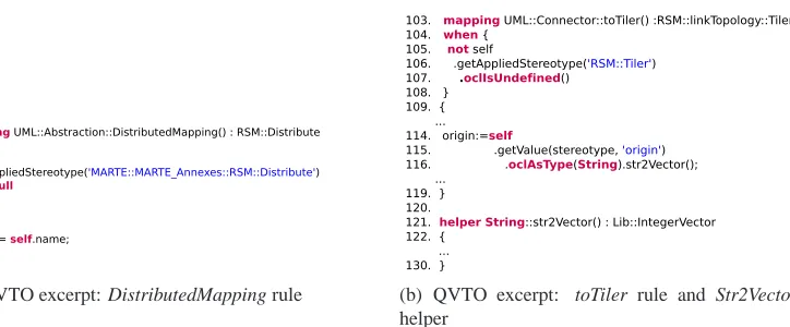
Figure2(a)shows an excerpt of the DistributedMapping mapping operation dealing with
Dis-tribute. The rule signature (line 54) exposes that this mapping is applied on instance of the Abstraction concept (owned by the UML metamodel) and produces instances of the Distribute
concept (owned by the RSM package of the Marte metamodel). The when section (line 55 to 59) expresses a guard that specifies the condition to execute the rule. This guard imposes that the
Abstraction element must be stereotyped as Distribute. Finally, the name property of the created Distribute has the same value than the name property of the UML Abstraction (line 64).
Figure2(b)presents an excerpt of the toTiler mapping (line 103 to 119) which creates a Tiler from a Connector stereotyped Tiler. The origin property owned by the Connector is an
Inte-gerVector. It is created from the origin tagged value contained by the Tiler stereotype (line 114
54. mapping UML::Abstraction::DistributedMapping() : RSM::Distribute 55. when {
56. self.
57. getAppliedStereotype('MARTE::MARTE_Annexes::RSM::Distribute') 58. != null
59. } 60. { ...
64. name := self.name; ...
67. }
(a) QVTO excerpt: DistributedMapping rule
103. mapping UML::Connector::toTiler() :RSM::linkTopology::Tiler 104. when {
105. not self
106. .getAppliedStereotype('RSM::Tiler') 107. .oclIsUndefined()
108. } 109. { ... 114. origin:=self
115. .getValue(stereotype, 'origin') 116. .oclAsType(String).str2Vector(); ...
119. } 120.
121. helper String::str2Vector() : Lib::IntegerVector 122. {
... 130. }
(b) QVTO excerpt: toTiler rule and Str2Vector helper
Figure 2: Excerpts of the UML to Marte transformation using QVTO
2.4 Scenarios for Model Synchronization
To illustrate the QVT trace limitations in contexts where a traceability mechanism is nevertheless very useful, we define four scenarios occurring in model synchronization. Such a context choice is pertinent for two main reasons. First, model synchronization usually uses traceability as main entry for its algorithm [MAL09]. Second, the nature of the information looked for in these scenarios is very common and frequently manipulated in other contexts.
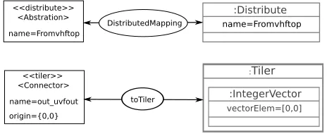
In order to make these scenarios a reality, an input and an output model have been defined and are partially represented in the figure3. Only the elements instantiating the concepts handled by the previously described rules are presented.
<<distribute>> <Abstration> name=Fromvhftop <<tiler>> <Connector> name=out_uvfout origin={0,0} :Distribute name=Fromvhftop :Tiler :IntegerVector vectorElem=[0,0] (a) (b)
Figure 3: Input (a) and Output (b) Model Excerpts
The model synchronization strategy is simplified; we are conscious that bigger issues are raised. However, it is enough to illustrate our purpose:
1. If an element is suppressed in the output model, then the input elements which lead to its creation should be suppressed. If these latter are involved in the generation of other elements in the output model, they also have to be deleted.
output model, they also have to be modified.
Conforming to these strategies, we define four scenarios representing a suppression/modification action on elements of the output model (figure3(a)).
Scenario 1: suppression of the Distribute instance.
Scenario 2: modification of the property name owned by the Distribute instance. Scenario 3: suppression of the IntegerVector instance owned by the Tiler instance. Scenario 4: modification of the property vectorElem owned by the IntegerVector instance.
In the next section these scenarios are developed using the QVT trace produced during the transformation.
3
Performing Model Synchronization Using the QVTO Trace
This section does not aim to propose a solution to the model synchronization issues, but to informally present the limitations of the QVT trace even in simple samples such as the scenarios previously described.
The QVT trace generated during the execution of the “UML to Marte” transformation is used to synchronize the models following the four scenarios successively.
Figure4sketches the part of this trace generated relative to the two rules previously presented. This trace contains two links. One expresses that the Fromvhftop Abstraction instance leads to the creation of the Fromvhftop Distribute instance by executing the DistributedMapping operation. The other link specifies that the toTiler operation uses the out uvfout Connector to create a Tiler instance.
<<distribute>> <Abstration>
name=Fromvhftop
<<tiler>> <Connector>
name=out_uvfout
origin={0,0}
:Distribute
name=Fromvhftop
:Tiler
:IntegerVector vectorElem=[0,0]
toTiler DistributedMapping
Figure 4: Produced QVT Trace View
3.1 Application of the Case Study
The realization of each scenario relies on an analysis of this trace.
Scenario 1: The Fromvhftop Distribute instance is removed. To synchronize the input model,
the elements of the input model leading to its creation must be also deleted. Analyzing the QVT trace, only the Abstraction instance enables this creation using the DistributedMapping operation. The synchronization here is quite simple: the Abstraction instance is deleted in the input model.
Scenario 2: The QVT trace does not provide enough information to determine the elements
Scenario 3: Synchronizing the models corresponds to the removal of the input model elements
involved in the creation of the IntegerVector. As in the previous scenarios, these elements cannot be identified using the QVT trace. The synchronization is thus compromised.
Scenario 4: Once again, synchronization is hardly enforceable because the QVT trace does
not provide links between the removed property and the element leading to its creation.
These four scenarios illustrate the inefficiency of the QVT trace to highlight links between input and output elements useful for example to perform model synchronization. Only the first scenario succeeds with such a trace. As the concepts, the properties need to be traced. Indeed, model synchronization may also concern properties such as present in the scenarios 2 and 4. Moreover, the scenario 3 illustrates that some concepts (e.g. IntegerVector) may be created using a helper. Thus traceability must also concern helpers and not only rules. These four scenarios show on very common actions upon a model (i.e modification/suppression) that the QVT trace has not a fine enough granularity.
3.2 The QVT Trace Policy
The Operational Mapping provides a trace generation policy relying only on mapping operation. According to the QVT specification, trace class instances are automatically created when
map-ping operation are executed. The traced elements refer only either to the input and the output
specified in the rule signature or to the rule parameters. The case study has shown the limit of this policy; other QVT language elements require attention.
3.2.1 The when section
Operational Mapping and Relation provides a guard mechanism through the when keyword. The
rule is executed only if this guard is satisfied. So the creation of an object relies not only on the element on which the rule has been applied, but also from all the elements/properties involved in the guard. Tracing every element involved in the creation of another one may be very useful in some cases, as illustrated in the case study.
3.2.2 The query and the helper operation
Additionally to the mapping, the Operational Mapping language provides two other operations;
query and helper.
The query is an operation associated to a simple request. It does not create/delete/modify any object. For this reason it seems not useful to trace the queries.
3.2.3 The Primitive Property
Primitive properties do not appear in the QVT trace since they are not used in the object resolu-tion mechanism. However, as illustrated in the case study, informaresolu-tion concerning them may be useful.
The experimentation and the observations made in this section concern the QVT Operational
Mapping language. However, they are also applicable to the Relation language since the trace
policy is relatively common to the three QVT languages.
4
QVT with the Local Trace
Two solutions can be envisaged to overtake the limitations of the QVT trace: enhance it or provide an alternative trace. We have chosen the second solution for two reasons. First, the QVT trace is dedicated to object resolution. Tracing helpers as mappings may lead to errors, since the QVT trace is internally used to object resolution; the helper could not be applied many times on the same element. Tracing the properties would not lead to errors but would change the trace purpose. Second, each QVT engine adopts its own implementation of the standard. Moreover, other transformation engines/languages are used. The alternative trace we provide, the local
trace, is fully independent from any transformation language.
Our local trace has been used to to gather fine grain information in order to localize errors in transformation [AMED09]. Moreover, the local trace has been used with different model formation languages such as Java and QVTO, showing its full independence from any trans-formation language; only its generation has to be adapted. In the following subsections, we present the local trace metamodel and its capacity to produce a trace model adapted to “classic” exploitation/exploration without loosing the original information contained in the QVT trace.
4.1 Local Trace Metamodel
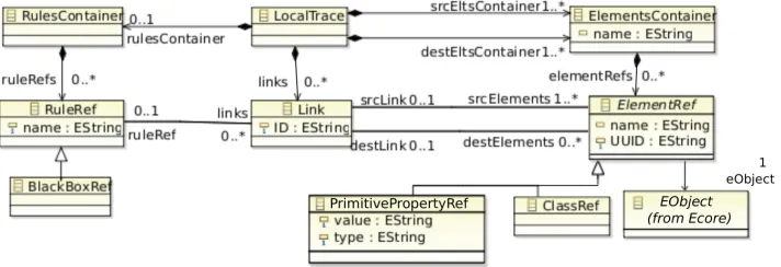
The metamodel presented in Figure5has already been described in [GED08,AMED09]. It is built around a minimal core close to the trace metamodel defined by Jouault in [Jou05]. The local trace metamodel is designed around three main concepts: Link, ElementRef and RuleRef. The other concepts of the metamodel are used to structure the trace models by providing containers.
4.1.1 The Link concept
The Link concept establishes a relationship between elements involved in the transformation. It connects all the input elements useful to create/modify/delete output elements.
4.1.2 The ElementRef concept
The ElementRef concept represents the different elements consummated and produced by the transformation. It directly points out the corresponding element of the input/output model through a reference to eObject. Moreover, to trace properties, distinction between model class and prim-itive type class property such as Integer or String is explicitly designed. An ElementRef is either a ClassRef or a PrimitivePropertyRef, respectively. PrimitivePropertyRefs own specific proper-ties: value and type which correspond to the value and the type of the traced property.
Transformation rules may involve many input and output elements for example through the QVT when sections. Similarly, the local trace metamodel provides a n-to-m connection between
Link and ElementRef. Thus the elements involved in a when section may be automatically traced
with the elements on which the rule is applied.
4.1.3 The RuleRef concept
RuleRef refers to the transformation rule, that creates it. Indeed, by regarding helpers1as a
side-effect operation, the RuleRef concept stores information concerning the rules and the helpers evaluated during a transformation and leading to the creation of trace Links.
The independence of our metamodel to any transformation language implies that it can easily be used without any adaptation in combination with various language. However, this indepen-dence obviously does not hold for the generation of the trace model, which depends on the used language. Concerning the QVT Operational language, we provide a plug-in fragment for the Eclipse platform and QVTO to generate the trace. Concretely, some classes used by QVTO are overridden. Such a mechanism enables us to generate the local trace without interfering in the transformation execution. Moreover, the trace is accessible all along the transformation execu-tion, serialized as a model at the end and can thus be exploited by external algorithms/software during or after the transformation execution.
5
Application of the Case Study with the Local Trace
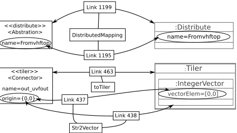
In this section, we apply the case study with the local trace. By construction, the generated local trace model contains all the information provided in the QVT trace and more. Figure6sketches a part of the generated local trace. The links express that the Fromvhftop Distribute instance of the output model has been created from the Fromvhftop Abstraction instance in the input model (link 1199). The rule DistributedMapping has created this Distribute instance. Moreover, links between properties provide finer grain information. Thus, for example, the name property of the Distribute instance in the output model has been generated from the name property of the
Abstraction instance, by the DistributedMapping rule (link 1195).
<<distribute>> <Abstration>
name=Fromvhftop
<<tiler>> <Connector>
name=out_uvfout origin={0,0}
:Distribute
name=Fromvhftop
:Tiler
:IntegerVector vectorElem=[0,0]
toTiler DistributedMapping
) *Vector +n,
-+n,0 +n, -2
+n,1 +n,
Figure 6: Generated Local Trace for the Case Study
Each scenario presented in section2is developed using the local trace.
Scenario 1: The local trace specifies that the Fromvhftop Distribute instance is associated to
only one link (Link 1199) having a unique source element the Fromvhftop Abstraction instance. Thus, to synchronize model in this case and adopting the strategy described in section 2, the
Abstraction instance is removed from the input model.
Scenario 2: The local trace and more precisely the Link 1195, enable one to identify the
element name property of the Abstraction instance in the input model as the element which creates the name property of theFromvhftop Distribute instance. Thus, to perform the model synchronization, the name property of the Abstraction instance must be also modified.
Scenario 3: The Link 438 of the local trace highlights that the IntegerVector instance has been
generated from the origin property owned by the Tiler instance. Thus, the suppression of the
IntegerVector instance leads to emptying the origin property in the input model.
Scenario 4: The local trace expresses with the Link 437 that, the vectorElem property
cre-ation relies on the origin property owned by the Tiler instance. The modificcre-ation applied on the
vectorElem property affects the origin property in the input model.
Applying the model synchronization scenarios of section2with the local trace succeeds. Each action performed on the output model concerns elements (i.e. property or class) that are traced. It is thus simple to find the input model elements which create them and then perform adequate modifications to synchronize the models.
6
Related Work
Traceability is widely spread in computer science domain. However, in this paper, we focus on traceability used in the context of model transformations.
Several metamodels have been proposed as the foundation of traceability approaches [Jou05, FHN06,VAB+
trace for ATL [YW09]. The proposed trace gathers fine grained information of the ATL transfor-mation execution. However, the implementation is really dependent from the ATL metamodel and the ATL Virtual Machine. Our local trace metamodel is an extension of the one defined by Jouault “core” trace providing a more finer grain trace and separating the rule concept from the link to ease manipulations.
In [FHN06], the authors define a metamodel closed to the Jouault’s one in order to provide a traceability mechanism to transformations written with the Kermeta language. Since the linked elements directly refers by Kermeta objects, they can correspond to class or primitive property, but such a distinction is not explicit in the metamodel. Moreover, this metamodel can manage many “steps” corresponding to a sequence of model transformations. Our local trace meta-model does not take in account meta-model transformation sequences (a.k.a transformations chain). To solve this problem, we introduced in [GED08], the global trace metamodel to store the lo-cal trace sequence. This metamodel links the input/output models with their lolo-cal trace. In our approach, preoccupations are split: the local trace is only used for the model to model transfor-mation tracing, whereas the global trace only deals with navigation through the local trace and its input/output models.
Other techniques to manage several traces, each one corresponding to one transformation in a chain, are proposed in [VAB+07] and [BDFB07]. In [BDFB07], the authors separate the
preoc-cupations providing two traceabilities. A traceability “in the small” dealing with model to model transformation and a traceability “in the large” to manage transformation chain. Their solution relies on megamodel to reference traces. In [VAB+07], the UniTI approach is not directly
de-signed to solve traceability issues. The main objective of the authors is to define a metamodel enhancing composition and reuse of transformations written in various languages. Nevertheless, this metamodel could be easily extended with concepts for global traceability.
Traceability is not a goal in itself. Its major interest lies in its ability to be used as an algo-rithm/approach input. In the case of the QVT trace, this algorithm corresponds to object reso-lution and so it is provided is perfectly adapted. However, to be used with common algorithms based on trace, the QVT trace does not gather enough information; alternative traces have to be generated.
In [WKS+09], the authors proposes a debugging support for the QVT Relation language based
on an alternative trace. They transform the QVT transformation to a colored Petri nets transfor-mation (using TROPIC) in order to take benefit from the traces produced by TROPIC. However, adaptation of such an approach to the QVT Operational Mapping seems difficult due to the complexity of this QVT language.
7
Conclusion
In this article, through a model synchronization example, we have shown that the QVT trace does not gather enough information for common algorithm requiring trace as input. Indeed, the QVT trace is designed for the object resolution mechanism. It is used internally by the transformation engine itself and can be invoked by the developer (using specific keywords). The information contained in this trace are relative only to some kind of elements (class and not property). Moreover, trace links are only one-to-one links focussing on the root patterns of the rules (i.e. elements involved in the rule signature).
Based on the case study, we have identified concepts useful to model synchronization but not contained in the QVT trace. Thus for example, all the elements appearing in patterns describing the condition to apply a rule or properties would deserve to be traced. Moreover, rules/mapping are not the only operations creating or modifying elements; helpers do it also, but only rules generate links in the QVT trace. We propose an alternative, the local trace metamodel managing all these aspects. It is language independent. Thus, it is possible to use the local trace whatever the transformation language used.
By gathering more information, the local trace can become large when dealing with huge models. One of the future challenges we need tackle is the specification of elements to trace in order to reduce the size of the trace model.
Bibliography
[AMED09] V. Aranega, J.-M. Mottu, A. Etien, J.-L. Dekeyser. Traceability Mechanism for Error Localization in Model Transformation. In ICSOFT. Bulgaria, July 2009.
[BDFB07] M. Barbero, M. Didonet, D. Fabro, J. B´ezivin. Traceability and provenance issues in Global Model Management. In ECMDA Traceability Workshop. Israel, 2007.
[Bor07] Borland. QVT - O. 2007. http://www.eclipse.org/m2m/qvto/doc.
[FHN06] J. Falleri, M. Huchard, C. Nebut. Towards a Traceability Framework for Model Trans-formations in Kermeta. In ECMDA Traceability Workshop. Spain, 2006.
[GED08] F. Glitia, A. Etien, C. Dumoulin. Traceability for an MDE Approach of Embedded System Conception. In ECMDA Traceability Workshop. Germany, 2008.
[HLR07] M. Hibberd, M. Lawley, K. Raymond. Forensic Debugging of Model Transformations. In MoDELS. USA, 2007.
[IEE91] IEEE. IEEE standard computer dictionary : a compilation of IEEE standard computer
glossaries. IEEE Computer Society Press, New York, NY, USA, 1991.
[Jou05] F. Jouault. Loosely Coupled Traceability for ATL. In ECMDA Workshop on
Traceabil-ity. Germany, 2005.
[KSWR09] A. Kusel, W. Schwinger, M. Wimmer, W. Retschitzegger. Common Pitfalls of Using QVT Relations - Graphical Debugging as Remedy. In ICECCS. USA, 2009.
[Kur08] I. Kurtev. State of the Art of QVT: A Model Transformation Language Standard. 2008.
[MAL09] I. Madari, L. Angyal, L. Lengyel. Traceability-based incremental model synchroniza-tion. W. Trans. on Comp. 8(10), 2009.
[NZR07] L. Naslavsky, H. Ziv, D. J. Richardson. Towards leveraging model transformation to support model-based testing. In ASE. USA, 2007.
[Obj03] Object Management Group, Inc. The Model Driven Architecture. Sept. 2003. http://www.omg.org/mda/.
[Obj07] Object Management Group, Inc. MOF Query / Views / Transformations. http://www.omg.org/docs/ptc/07-07-07.pdf, July 2007. OMG paper.
[OMG07] UML 2 Superstructure. http://www.omg.org/spec/UML/2.1.2/, Nov. 2007.
[OMG08] OMG. UML Profile for MARTE, Beta 2. http://www.omgmarte.org/Documents/Speci-fications/08-06-09.pdf, June 2008.
[PDK+
10] R. Paige, N. Drivalos, D. Kolovos, C. Power, G. Olsen, S. Zschaler. Rigorous Identi-fication and Encoding of Trace-Links in Model-Driven Engineering,. Journal of
Soft-ware and Systems Modelling, 2010.
[VAB+
07] B. Vanhooff, D. Ayed, S. V. Baelen, W. Joosen, Y. Berbers. UniTI: A Unified Trans-formation Infrastructure. In MoDELS. USA, 2007.
[WKS+
09] M. Wimmer, A. Kusel, J. Sch¨onb¨ock, G. Kappel, W. Retschitzegger, W. Schwinger. Reviving QVT Relations: Model-Based Debugging Using Colored Petri Nets. In Sch¨urr and Selic (eds.), MoDELS. USA, 2009.
[YW09] A. Yie, D. Wagelaar. Advanced Traceability for ATL. In 1st International Workshop