Available online throug
ISSN 2229 – 5046
EFFECT OF SURFACE ROUGHNESS ON SQUEEZE FILM CHARACTERISTICS
BETWEEN PARALLEL STEPPED PLATES WITH RABINOWITSCH FLUID
N. B. NADUVINAMANI
1*, SIDDANAGOUDA A
2. AND S. S. SIDDAPUR
31
Department of Mathematics,
Gulbarga University, Kalaburagi – 585106, India.
2
Department of Mathematics,
Appa Institute of Engineering and Technology, Kalaburagi – 585103, India.
3
Department of Mathematics,
Government First Grade College, Vijayapur. 586101, India.
(Received On: 30-05-16; Revised & Accepted On: 16-06-16)
ABSTRACT
T
he purpose of this paper is to investigate the effect of surface roughness on squeeze film characteristics between parallel stepped plates with non-Newtonian pseudoplastic lubricants- Rabinowitsch fluid model. On the basis of Christensen stochastic theory the analysis is done for the two types of one dimensional surface roughness patterns, viz. longitudinal and transverse roughness patterns. Expressions for the squeeze film pressure, the load carrying capacity and squeeze film time are obtained. The effect of transverse (longitudinal) roughness pattern is to increase (decrease) the squeeze film pressure, load carrying capacity and squeeze film time as compared to the corresponding smooth case.Keywords: Rabinowitsch fluid model, squeeze film, surface roughness, parallel stepped plates.
1. INTRODUCTION
The study of bearings with an assumption of bearing surfaces are smooth will not predict the bearing performance accurately. Stresses generated when rough surfaces come in to contact and play an important role in most mechanism of friction and wear. Because of this, in recent years the study of surface roughness has been studies with greater importance in the study of bearings, since the surface roughness is inherent to the process used in their manufacture.
Height of the surface roughness may range from 0.05μm of less on polished surfaces to 10μm medium machined surfaces. Due to the random character of the surface roughness, a stochastic approach has been employed to mathematically model the surface roughness by several investigators. Christensen [1] developed a stochastic model for the study of surface roughness on hydrodynamic lubrication of bearings. The stochastic concept of transverse and longitudinal roughness on the steady state behaviour of journal bearings is analyzed by Christensen and Tonder [2, 3] Hsu. et.al [4] analyzed the effects of surface roughness and rotating Inertia on the squeeze film characteristics of parallel circular disks with the development of modern machine equipments the increasing use of non-Newtonian fluids as lubricants are becoming of great interest. According to recent experimental investigations [5, 6], base oil blended with long chained additives is found to improve lubricating properties and reduce friction and surface damage. Several micro continuum theories have been proposed to describe the rheological behaviours of such non-Newtonian lubrication a better way. Recently, Naduvinamani et al. [7] analyzed, combined effects of surface roughness and couple stresses on squeeze film lubrication between porous circular stepped plates. This theory has been widely used to investigate the effects of couple stresses on the performance of different type of fluid film bearings such as slider bearings [8, 9], journal bearings [10, 11].
Rabinowitsch fluid model is one of the models to establish the non-linear relationship between the shearing stress and shearing strain rate which can be described for one dimensional fluid flow as
3 xy xy
u y
τ +κτ =µ∂
∂ (1)
Corresponding Author: N. B. Naduvinamani
1*© 2016, IJMA. All Rights Reserved 39
where
µ
denote the zero shear rate viscosity and κ denotes the non linear factor which describes the non-Newtonian effects of the lubricant which will be referred to as coefficient of pseudo plasticity. This model can be applicable to Newtonian, dilant and pseudoplastic lubricants forκ
=0,κ
<
0
andκ
>0,respectively. Recently several researchers have investigated the non-Newtonian effect of Rabinowitsch lubricants on various type of bearings. Lin et al. [12], studied the non-Newtonian effect of Rabinowitsch fluid model on the slider bearings, parallel annular disks by Lin, [13] and parallel rectangular squeeze film plates by Lin et al. [14]. A squeeze film characteristics between a long cylinder and a flat plate by Singh et al. [15], non-Newtonian effects on the squeeze film characteristics between a sphere and a flat plate lubricated with Rabinowitsch Fluid model studied by Singh and Gupta[16].In this paper, the effect of surface roughness on the squeeze film characteristic between stepped plates with Rabinowitsch fluid is analyzed which has not been studied so for.
Figure 1: Squeeze film between rough parallel stepped plates.
2. MATHEMATICAL FORMULATION OF THE PROBLEM
Consider a squeeze film between two parallel stepped plates approaching each other with a normal velocity V dH
dt
=
the bearing surface is rough (at y = 0) as shown in figure1. The lubricant in the film region is taken to be non-Newtonian Rabinowitsch fluid. Body forces and body couples are considered to be absent.According to hydrodynamic lubrication applicable to thin film (Dowson,1961) the field equations governing the one dimensional motion of an incompressible non-Newtonian fluid- Rabinowitsch fluid model in Cartesian co-ordinates (x,y,z) system becomes
0
u v x y
∂ ∂ + =
∂ ∂ (2)
xy
p
x
y
τ
∂
∂
=
∂
∂
(3)0
p y
∂ =
∂ (4)
Which are solved under boundary conditions for velocity components given by
(i) At the upper surface y = H, u = 0 and v = -V = dH
dt
−
5(a)
(ii) At the lower surface y = 0, u = 0 and v = 0 5(b)
Let film thickness H is to be made up of two parts and is given by
( , , ) i i s
H =h +h x y ξ for i = 1,2
2. SOLUTION OF THE PROBLEM
Integrating equation (3) with respect to y subject to the boundary conditions 5(a) and 5(b) and using constitutive equation (1) the expression for velocity component can be obtained as
3 4
* 3 2 2 3
1 3 1
( )
2 2 4 4
p p y
u y y H z H y H yH
x
κ
xµ
∂ ∂
= ∂ − + ∂ − + −
(6)
Using equation (6) in the continuity equation (2) and integrating with respect to y under the relevant boundary conditions 5(a) and 5(b) for y, the modified Reynold’s type equation for non-Newtonian Rabinowitsch fluid is obtained in the form
3
3 3 * 5
12 20
p p H
H H
x x
κ
xµ
t
∂ ∂ + ∂ = − ∂
∂ ∂ ∂ ∂ (7)
3. STOCHASTIC REYNOLDS EQUATION
Let f(hs) be the probability density function of the Stochastic film thickness hs. Taking average of the equation (7)
with respect to f(hs) we obtain
3
3 ( ) 3 * 5 ( )
( ) ( ) 12
20
E p E p H
E H E H
x x
κ
xµ
t
∂ ∂ + ∂ = − ∂
∂ ∂ ∂ ∂ (8)
where the expectancy operator 𝐸𝐸(•) is defined by
( )• ( )• ( s) s
E f h dh
∞
−∞
=
∫
(9)In accordance with the Christensen [1], it is assumed that
2 2 3 7
35
( ) .
( ) 32
0 elsewhere
s s
s
c h c h c
f h c
− − < <
=
(10)
Where σ = c/3 is the standard deviation.
In accordance with the Christensen (1970) Stochastic theory for the hydrodynamic lubrication of rough surfaces, the analysis is done for two types of one- dimensional surface roughness pattern viz. one- dimensional longitudinal surface roughness pattern and transverse roughness pattern.
3.1. One - dimensional longitudinal roughness pattern
In this case the roughness is assumed to have the form of long, narrow ridges and valleys running in the x- direction. The film thickness therefore described by a function of the form
( , ) i i s
H =h+h yξ for i = 1,2
and stochastic modified Reynolds equation takes the form
3
3 ( ) 3 * 5 ( ) ( )
( ) ( ) 12
20
E p E p E H
E H E H
x x
κ
xµ
t
∂ ∂ + ∂ = − ∂
∂ ∂ ∂ ∂
3
3 ( ) 3 * 5 ( )
( ) ( ) 12
20
E p E p
E H E H V
x x
κ
xµ
∂ ∂ + ∂ = −
∂ ∂ ∂ (11)
3.2 One dimensional Transverse roughness pattern
In this type the roughness is assumed to have the form of long narrow ridges and furrows running in the direction perpendicular to the direction of sliding i.e. in the y-direction. The film thickness is therefore described by the function of the form
( , ) i i s
H =h+h x ξ for i = 1, 2 And stochastic modified Reynolds equation take
3 *
3 5
1 ( ) 3 1 ( )
12
1 20 1
E p E p
V
x x x
© 2016, IJMA. All Rights Reserved 41
Equations (11) and (12) together can be written as
(
)
(
)
3 ( ) 3 *(
(
)
)
5 ( ) 3, , 12
20
E p E p
G H c G H c V
x x
κ
xµ
∂ ∂ + ∂ = −
∂ ∂ ∂ (13)
Where
1
( ). for roughness
( , ) 1
for transverse roughn longitudin
s al
e s
E H
G H c E H − =
2 2 3 7 35 ( ) ( ) 32 c s s c
E H H c h dh
c −
=
∫
−2 2 3
7 ( ) 1 35 32 c s s c c h E dh
H c − H
− =
∫
Equation (13) is a non- linear equation in y hence it is not easy to find it’s solution in closed form using analytical methods. Hence the classical perturbation method is used to find its solution. The squeeze film pressure can be perturbed as
*
0 1
p= p +κ p (14)
Substituting into the Reynold’s type equation (13) and neglecting the higher order terms of
κ
*, the two separated equations governing the squeeze film pressure p0 and p1 can be derived respectively.(
)
3(
0)
( , )
E p
12
h
G H c
x
x
µ
t
∂
∂
= −
∂
∂
∂
∂
(15a)(
)
5 ( 0) 3(
)
3 ( 1)3
( , ) ( , ) 0
20
E p E p
G H c G H c
x x x
∂ ∂
∂ + =
∂ ∂ ∂ (15b)
The modified Reynold’s type equation for determining the squeeze film pressure is obtained from the equation (15 a) and (15b) and using boundary conditions
( ) 0
E p x
∂ =
∂ at x=0
Gives
(
)
(
)
0
3
( ) 12
,
i
i
E p Vx
x G H c
µ
∂ −
=
∂ (16a)
(
)
(
)
3 1
7
( ) 1296
5 ,
i
i
E p Vx
x G H c
µ
∂ = −
∂ (16b)
Where hi =h1 and pi = p1for the region
0
≤ ≤
x KL
(17a)hi =h2 and pi = p2for the region
KL x L
≤ ≤
(17b)(
)
1( ). for roughness
1
for transverse r longitudin oughn s a e s l i i i i E H
G H c E H − = Where Hi =hi+hs
The relevant boundary conditions for the pressure are
1 2
( ) ( )
E p =E p at
x KL
=
(18a)2
( )
E p =o at
x
=
L
(18b)For the Region- I:
2 2 2 2 2 4 4 4 4 4
*
1 3 3 7 7
1 1 2 2 1 1 2 2
(1 K ) 324 (1 K )
( ) 6
5
( ( , )) ( ( , )) ( ( , )) ( ( , ))
K L x L K L x L
E p V V
G H c G H c G H c G H c
µ − − κ µ − −
= + − +
(19)
and for the Region - II:
2 2 4 4
*
2 3 7
2 2 2 2
324 )
( ) 6
5
( ( , )) ( ( , ))
L x L x
E p V V
G H c G H c
µ − κ µ −
= −
The non-dimensional pressure in the region I (19) and in the region II (20) are obtained in the form
(
2 *2)
(
2)
(
4 *4)
(
4)
* 1
1 2 * 3 * 3 * 7 * 7
1 1 2 2 1 1 2 2
54
1
1
(
)
(
(
, ))
(
(
, ))
5
(
(
, ))
(
(
, ))
6
P
K
x
K
K
x
K
E P
G H
c
G H
c
G H
c
G H
c
VL
α
µ
−
+
−
−
+
−
=
=
−
(21)(
*2)
(
*4)
* 2
2 2 * 3 * 7
2 2 2 2
54
1
1
(
)
(
(
, ))
5
(
(
, ))
6
P
x
x
E P
G H
c
G H
c
VL
α
µ
−
−
=
=
−
(22)* 2 * * 1 * 2
1 2
0 0
Where
L x
,
x
,
h
h
,
h
h
L
h
h
α κ
=
=
=
=
The load carrying capacity E(W) is obtained in the form
1 2
0
( ) 2 ( ) 2 ( )
KL L
KL
E W = b
∫
E p dx+ b∫
E p dx (23)The non-dimensional mean load carrying capacity W* is obtained in the form
3 3 3 5 5
* 2
3 * 3 3 * 7 7
1 2 1 2
( ) (1 K ) 324 (1 K )
25
8 ( ( , )) ( (1, )) ( ( , )) ( (1, ))
E W h K K
W
b VLµ G H c G c α G H c G c
− −
= = + − +
(24)
writingV dh2
dt −
= in the equation (24) the squeezing time for reducing the film thickness from the initial value h0 of h2 to a final value hf is given by
0
3 3 3 5 5
* 3
2
3 3 7 7
1 1 2 2 1 1 2 2
8 1 324 1
( ) ( ( , )) ( ( , )) 25 ( ( , )) ( ( , )) f
h
h
bL K K K K
t L dh
E W G H c G H c G H c G H c
µ
κ
− − − = = + − +
∫
(25)which in the non- dimensional form is
* 1
2 3 3 5 5
* 0 *
2
3 * * * 3 * * 3 * * * 7 * * 7
1 2 3 2 2 1 2 3 2 2
( ) 1 324 1
25
8 ( ( , , )) ( ( , , )) ( ( , , )) ( ( , , ))
f s s s s
h
E W h t K K K K
t dh
b L G h h h C G h h C α G h h h C G h h C
µ − − = = + − +
∫
(26)Where * 0 ; f f h h h
= 2* 2 0
;
h
h
h
=
* 0;
s sh
h
h
=
0;
c
C
h
=
* 33 0
;
h
h
h
=
3. RESULTS AND DISCUSSION
In the present paper, the effect of surface roughness on the squeeze film lubrication between parallel stepped plates with Rabinowitch fluid has been analysed on the basis of the Christensen Stochastic theory for the study of rough surfaces. By considering two different types of one dimensional roughness pattern viz. longitudinal roughness pattern and transverse roughness pattern. The effect of surface roughness is characterised by roughness parameter c. The limiting case of
c
→
0
corresponds to smooth case studied by Naduvinamani et al. [17].3.1. Load carrying capacity
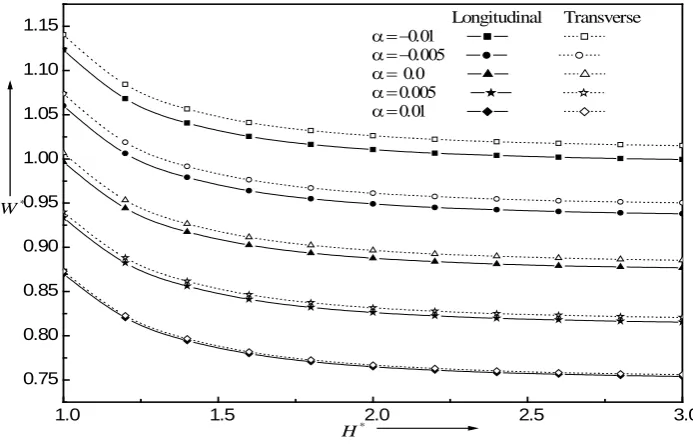
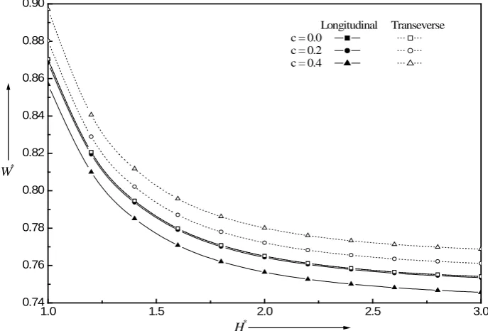
The variation of non-dimensional load carrying capacity W* with H* for different values of α with K= 0.5 and c = 0.1 is shown in figure 2 for both the longitudinal and transverse roughness patterns. It is observed that, the load carrying capacity W* decreases for increasing value of H* for both longitudinal and transverse roughness patterns. Further, it is also observed that W* increases for decreasing values of α, i.e. load carrying capacity increases for dilatant fluids and decreases for pseudoplastic lubricants for both type of roughness patterns. The variation of non-dimensional load carrying capacity W* with H* for different values of K with α= 0.01 and c = 0.2 is shown in figure 3. for both type of roughness patterns. It is observed that W* decreases for increasing values of K The increasing value of K leads to increase the step region and hence increase in the area of the fluid film and hence the decrease in pressure and load carrying capacity. From the figure 4 It is observed that increasing values of roughness parameter c, the load carrying capacity W* increases for transverse roughness pattern and decreases for the longitudinal of roughness pattern.
3.2. Squeeze Film Time
The variation of non dimensional squeeze film time t* with * f
h for different values of α with c = 0.2, K = 0.5 and
* 3 0.15
h = . is shown in the Fig. 5. for both type of roughness patterns. A significant increase in t* is observed for dilatant fluids as compared to the Newtonian case. Further the increase (decrease) in t* is more for transverse (longitudinal) roughness pattern. Fig.6. depicts the variation of non- dimensional squeeze film time t* with *
f
© 2016, IJMA. All Rights Reserved 43
K with α = 0.01, c = 0.2 and * 3 0.15
h= as values of K increases the squeeze film time decreases in both longitudinal and transverse roughness patterns. Fig.7. depicts the variation of non – dimensional squeeze film time t* with *
f
h For
different values of c with α= 0.01, K = 0.4 and * 3 0.15
h= , as c increases t* increases (decreases) for longitudinal (transverse) roughness pattern in case of pseudoplastic fluids (
α =
0.01
) where as the reverse trend is observed for the dialatant lubricants ( α= −0.01) as shown in Fig.8.4. CONCLUSIONS
The squeeze film lubrication between rough stepped plates with Rabinowitsch fluid is presented in this paper. It is found that there is significant increase in load carrying capacity for dilatant fluids as compared to the corresponding Newtonian fluids for both longitudinal and transverse roughness pattern whereas the reverse trend is observed for the pseudoplastic lubricants. The response time t* increases for decreasing values of α, i.e. the response time is more for dilatant lubricants and less for pseudoplastic lubricants
REFERENCES
1. Christensen. H. Stochastic models for hydrodynamic lubrication of rough surfaces, J Proc. Instn. Mech. Engrs.
184(1969-70), 1013-1026.
2. Christensen. H., Tonder. K., The hydrodynamic lubrication of rough bearing surfaces of finite width,
Transactions of the ASME-Journal of Lubrication Technology. 93(1971), 324–330.
3. Christensen. H. and Tonder. K. The hydrodynamic lubrication of rough journal bearing, J. Lubr. Tech., 95 (1973), 166-172.
4. Hsu. C.H, Lai. C, Lu R.F, Lin. J.R. Combined effects of surface roughness and rotating Inertia on the squeeze film characteristics of parallel circular disks. Journal of Marine Science and Technology.17 (2009), 60–66. 5. Oliver. D.R. Load enhancement effects due to polymer thickening in a short journal bearings, Journal of Non-
Newtonian Fluid Mechanics.,30 (1988),185–196.
6. Scott. W., Suntiwattana .P. Effect of oil additives on the performance of a wet friction clutch material, Wear.,
181 (1995), 850–855.
7. Naduvinamani. N.B., Siddanagouda A. J. Combined effects of surface roughness and couple stresses on
squeeze film lubrication between porous circular stepped plates, Journal of Engineering Tribology., 221 (2007), 525-534.
8. Lu. R.F., Ho., M.H., and Lin, J.R., A Study of Steady-state performance and Dynamic Characteristics for Wide Rayleigh Step Slider Bearings, Journalof Science and Technology,14 (2005), 205-211.
9. Ramanaish. G., Squeeze films between finite plates lubricated by fluids with couple stress, Wear, 54(1979), 315-320.
10. Naduvinamani. N.B., Hiremath P.S. and Gurubasavaraj G., Effect of surface roughness on the static
Characteristics of rotor bearings with couple stress fluids, Comp. and Stru.,80(2002), 1243-1253.
11. Naduvinamani. N.B., Hiremath, P.S. and Gurubasavaraj, G. Squeeze film Lubrication of a short porous journal bearing with couple tress fluids Tribology International, 34(2001), 739-747.
12. Lin.J. R., Non-Newtonian effect on the dynamic characteristics of one dimensional slider bearings;
Rabinowitsch fluid model, Tribology Letters,10(2001) 237-243.
13. Lin.J.R., Non-Newtonian Squeeze film characteristics between parallel annular disks: Rabinowitsch fluid
model, Tribology international, Vol. 52, 2012, pp. 190-194.
14. Hung,J. R., Chu.L.M., Liaw. W.L., Lee, P.H., and Lin.J.R. Effect of non- Newtonian Rabinowitsch fluids in wide parallel rectangular squeeze- film plates, Industrial lubrication and Tribology, 65 (2013)328-332. 15. Singh, U. P., Gupta, R. S., Kapur, V. K. On the Squeeze film Characteristics between a long cylinder and a
flat plate; Rabinowitsch fluid model, Proceedings of the Institution of Mechanical Engineering, Tribology,
227(2013), 34-42 .
16. Singh, U. P., Gupta, R. S., Non-Newtonian effects on the Squeeze Film characteristics between a sphere and a flat plate :Rabinowitsch Fluid model. Advances in Tribology 2012(2012). Article ID 571036, 1-7.
17. Naduvinamani. N.B., Siddanagouda. A., Siddapur. S.S. On the non-Newtonian effects of Rabinowitsch fluid
on the squeeze film characteristics between parallel stepped plates, International Journal of Mathematical Archive- 6(7) (2015), 228-235.
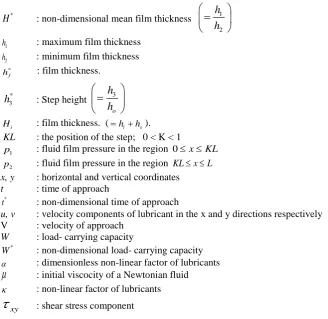
NOTATION
b : bearing width
c : maximum asperity deviation from the nominal film height.
C : dimensionless roughness parameter ( c /
h
2)*
H : non-dimensional mean film thickness 1
2
h
h
=
1
h : maximum film thickness
2
h : minimum film thickness
* f
h
: film thickness.
h
3* : Step height 3o
h
h
=
i
H : film thickness. (=hi+hs).
KL : the position of the step; 0 < K < 1
1
p : fluid film pressure in the region 0≤ ≤x KL
2
p : fluid film pressure in the region KL≤ ≤x L
x, y : horizontal and vertical coordinates
t : time of approach
*
t : non-dimensional time of approach
u, v : velocity components of lubricant in the x and y directions respectively
V : velocity of approach
W : load- carrying capacity
*
W : non-dimensional load- carrying capacity
α : dimensionless non-linear factor of lubricants
µ
: initial viscocity of a Newtonian fluidκ : non-linear factor of lubricants
xy
τ
: shear stress componentLIST OF FIGURE CAPTIONS
Figure 1: Sqeeze film between rough parallel stepped plates.
Figure 2: Variation of non-dimensional load carrying capacity W*with *
H for different values of αwith K = 0.5 and c = 0.1
Figure 3: Variation of non-dimensional load carrying capacity W*with *
H for different values of K with α = 0.01 and c = 0.2
Figure 4: Variation of non-dimensional load carrying capacity *
W with H*for different values of c with α = 0.01 and K = 0.5
Figure 5: Variation of non-dimensional time of approach *
t with * f
h for different values of α with c = 0.2, K = 0.5 and
*
0.15
s
h =
Figure 6: Variation of non-dimensional time of approach *
t with * f
h for different values of K with α = 0.01, c = 0.2, and *
0.15
s
h =
Figure 7: Variation of non-dimensional time of approach *
t with * f
h for different values of c with α = 0.01, K = 0.4, and *
0.15
s
h = .
Figure 8: Variation of non-dimensional time of approach *
t with * f
h for different values of c with α = - 0.01, K = 0.4, and *
0.15
s
© 2016, IJMA. All Rights Reserved 45
1.0 1.5 2.0 2.5 3.0
0.75 0.80 0.85 0.90 0.95 1.00 1.05 1.10 1.15
*
H
*
W
Figure 2. Variation of non-dimensional load carrying capacity W*
with H* for different values of α with K = 0.5 and c=0.1
Longitudinal Transverse
α = −0.01
α = −0.005
α = 0.0
α = 0.005
α = 0.01
1.0 1.5 2.0 2.5 3.0
0.65 0.70 0.75 0.80 0.85 0.90
*
H
*
H
* W *
W
Figure 3. Variation of non-dimensional load carrying capacity with for different values of K with α = 0.01 , c = 0.2
© 2016, IJMA. All Rights Reserved 46
1.0 1.5 2.0 2.5 3.0
0.74 0.76 0.78 0.80 0.82 0.84 0.86 0.88 0.90
W*
H*
Figure 4. Variationof non-dimensional load carrying capacity W* with H* for different valuse of c with K = 0.5 and α = 0.01
Longitudinal Transeverse c = 0.0 c = 0.2 c = 0.4
0.2 0.4 0.6 0.8 1.0
0.0 0.2 0.4 0.6 0.8 1.0 1.2 1.4 1.6 1.8 2.0 2.2
hf * t*
Fig 5. Variation of non-dimensional time of approach t* with hf * for different values of α with c = 0.2, K = 0.5,hs = 0.15
Longitudinal Transverse α = −0.01
α = −0.005 α = 0.0 α = 0.005
© 2016, IJMA. All Rights Reserved 47
0.2 0.4 0.6 0.8 1.0
0.0 0.1 0.2 0.3 0.4 0.5
t*
h*f
Figure.6 Variation of non-dimensional time of approach t* with h*f for different values of K with α = 0.01, c = 0.2, h*s = 0.015
Longitudinal Transeverse K = 0.2 K = 0.4 K = 0.6
0.2 0.4 0.6 0.8 1.0
0.0 0.1 0.2 0.3 0.4 0.5 0.6
h*f
t*
Figure.7 Variation of non-dimensional time of approach t* with h*f for different values of c with α = 0.01, K = 0.4, h*s =0.15
Longitudinal Transeverse c =0.0
0.0 0.2 0.4 0.6 0.8 1.0 0.0
0.5 1.0 1.5 2.0 2.5 3.0 3.5 4.0 4.5 5.0 5.5
h*f
*
t
Figure.8 Variation of non-dimensional time of approach t* with h*f for different values of c with α = − 0.01, K = 0.4, h*s = 0.15
longitudinal Transverse c = 0.0
c = 0.1 c = 0.2 c = 0.3
Source of support: Nil, Conflict of interest: None Declared