Comparison of Conventional and Cone Beam CT synthesized Cephalograms By
Vandana Kumar
A thesis submitted to the faculty of the University of North Carolina at Chapel Hill in partial fulfillment of the requirements for the degree of Master of Science in the Department of
Diagnostic Sciences and General Dentistry, School of Dentistry.
Chapel Hill 2007
Approved by:
Advisor: Dr. John Ludlow DDS, MS, FDS RCSEd
ABSTRACT Vandana Kumar
“In vitro Comparison of Conventional and Cone Beam Synthesized Cephalograms” (Part I), and “In vivo Comparison of Conventional and Cone Beam Synthesized
Cephalograms utilizing patient data” (Part II) (Under the direction of Dr John Ludlow)
The purpose of this study was to determine whether Cone Beam Computed
Tomography (CBCT) synthesized cephalograms provide the same measurement accuracy
and precision as conventional cephalograms. In Part I, cephalometric measurements of
conventional and CBCT synthesized orthogonal or perspective projections of 10 skulls were
compared with each other and with the actual skull measurements. In Part II, actual patient
data was used to compare the three imaging modalities and both soft and hard tissue
landmarks were utilized.
This study demonstrated that most cephalometric measurements are not different for
conventional and CBCT synthesized orthogonal and the perspective projections. Although
there is a statically significant difference between mid-sagittal image measurements
compared to actual skull measurements, these differences are very small .and are unlikely to
have clinical relevance. Both of the projections can be used with an expectation of precision
TABLE OF CONTENTS
LIST OF TABLES ... v
LIST OF FIGURES... vi
LIST OF ABBREVIATIONS ... vii
I. INTRODUCTION ... 1
II. MANUSCRIPT I - “In vitro Comparison of Conventional and Cone Beam Synthesized Cephalograms”... 6
Abstract ... 7
Introduction ... 9
Materials and Methods ... 11
Statistical analysis ... 14
Results ... 14
Discussion ... 15
References ... 27
III. MANUSCRIPT II - “In vivo Comparison of Conventional and Cone Beam Synthesized Cephalograms... 29
Abstract ... 30
Introduction ... 31
Materials and Methods ... 33
Statistical analysis ... 35
Discussion ... 35
References ... 50
IV. DISCUSSION & CONCLUSIONS ... 52
LIST OF TABLES
Table Page
1. Measurements utilized in manuscript 1... 23
2. Linear measurements from three imaging modalities (mm) ... 24
3. Angular measurements from three imaging modalities (degrees) ... 25
4a. ANOVA test of Actual Difference and Absolute Difference between image measurement and skull measurement of three mid-sagittal measurements for three imaging modalities ... 25
4b. Tukey Test of significant ANOVA factor (Image Modality for image-skull
measurement Difference ... 26
4c. Tukey Test of significant ANOVA factor (Image Modality) for Absolute Value of image-skull measurement... 26
5. Measurements utilized in manuscript 2... 45
6. Differences between linear measurements (mm) from three imaging modalities ... 46
7. P-values from the paired t-test for the linear measurements from three imaging modalities ... 47
8. Differences between angular measurements (degrees) from three imaging modalities ... 48
LIST OF FIGURES
Figure Page
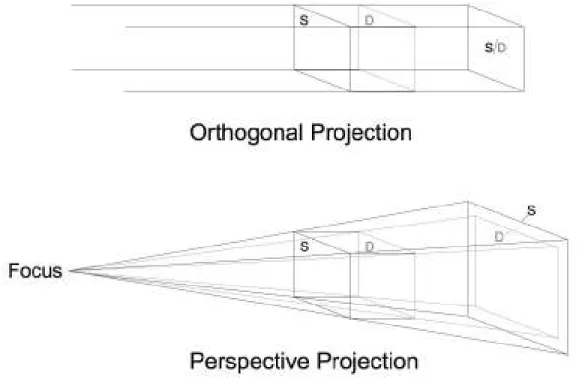
1. Orthogonal and perspective projections. Source side (S) and detector side (D) elements of a 3D object are not magnified in an orthogonal projection. In a perspective
projection, S and D are magnified to differing degrees ... 20
2. Orthogonal CBCT projection without magnification (a); ... 21
Perspective projection projection with 7.5% simulated magnification (b); ... 21
Conventional cephalogram of skull with inherent magnification of 7.5%(c) ... 22.
3. Dolphin 3D soft and hard tissue virtual model ... 41
4. Orientation of the Dolphin 3D virtual model ... 41
5. Angle instrument used in the study ... 42
6a. Using angle instrument to record the natural head position in the conventional cephalogram ... 42
6b. Using angle instrument to simulate the natural head position in the CBCT synthesized cephalogram ... 43
7. Orthogonal CBCT projection without magnification (a); ... 43
Perspective projection with 7.5% simulated magnification (b); ... 44
LIST OF ABBREVIATIONS
CBCT Cone Beam Computed Tomography
2D Two-dimensional
3D Three-dimensional
CT Computed Tomography
ANOVA Analysis of Variance
MANOVA Multivariate analysis of variance
Cm Centimeter
Dpi Dots per inch
DF Degrees of Freedom
DICOM Digital Imaging & Communications in Medicine
Tukey HSD Tukey Honestly significant difference
SOD Source to object distance
SID Source to image receptor distance
M Magnification
mm Millimeter
SD Standard deviation
LFH Lower Face Height (ANS-Me)
UFH Upper Face Height (N-ANS)
TFH Total Anterior Face Height (N-Me)
MnL Mandibular Unit length (Co-Gn)
MxL Maxillary Unit Length (Co-ANS)
BN B to N with respect to true vertical
PgN Pg to N with respect to true vertical
OJT Overjet
SNA Sella-Nasion-A
SNB Sella-Nasion-B
FMA Frankfort-Mandibular plane Angle
USN Upper Incisor-Sella/Nasion
LMP Lower Incisor-Mandibular Plane
ST Soft tissue
LN Lower lip to N with respect to true vertical
UN Upper lip to N with respect to true vertical
PgN Pg to N with respect to true vertical
ANS Anterior Nasal Spine
Me Menton
N Nasion
Co Condylion
Gn Gnathion
Pg Pogonion
A Point A
B Point B
S Sella
MP Mandibular Plane (Me-Go)
Conv Conventional cephalogram
CBCT-o CBCT synthesized orthogonal projection
INTRODUCTION
Background and Significance
Cephalometric radiography is primarily used to describe the morphology and growth
of the craniofacial skeleton. It is considered a valuable diagnostic aid in orthodontics for
treatment planning and evaluating treatment results. Cephalometric analysis requires
identifying specific landmarks and calculating various angular and linear dimensions.1
Lateral cephalometric radiographs, like all transmission radiographs, collapse the
three-dimensional (3D) structure in a two-three-dimensional (2D) plane. Two types of errors occur with
this approach: errors of projection, and errors of identification.
Errors of projection occur due to imperfect enlargements caused by the unequal
distances between the focus, the objects of interest (landmarks) within the skull and the
image receptor. Magnification differences of 7-8% between the x-ray source side & image
receptor side anatomy influence measurement & cause either underestimation or
overestimation of asymmetry. Imaging of structures that are not situated in the midsagittal
plane and that appear bilaterally, produce a dual image on the radiograph.2 Deviations from
the standard projection geometry and misalignment of the cephalostat together with rotation
of the patients head in the cephalostat in any plane result in the errors of projection. 3, 4
Errors of identification occur due to observer variability in locating the various
landmarks. Various factors like quality of radiographic image, precision of landmark
definition, and reproducibility of landmark location as well as operator variability may allow
Broadbent’s introduction of the cephalostat underscored a philosophy of coordinating
both the lateral and frontal head films to define the craniofacial form. But this is difficult to
achieve and yields less accurate measurements than true anatomic values. The approach is
reliant on identification of the same point on both radiographs and uses geometry to calculate
the 3D position. This has the main limitation of inexact correspondence of landmark location
on the 2 radiographs. Points not visible on both radiographs cannot be used. In addition;
these images provide no information about anatomical relationships in the coronal plane.7
The introduction of digital imaging in dentistry generated many new research
initiatives aimed at unlocking the diagnostic potential of radiography through image
processing. Some of these initiatives have resulted in meaningful applications that have been
shown to increase diagnostic utility. Some studies have compared measurements and
superimpositions on analog radiographs with those made on scanned digital images and
showed that the measurement differences between the original cephalograms and the
digitized images are statistically significant but clinically acceptable.8-10 Digital
cephalometric radiography can yield better or comparable performance in landmark
identification than film, but digital images also suffer from the limitations of conventional
cephalograms including magnification, distortion and superimposition of the anatomical
structures.
Cephalometric superimposition and shape analysis are other ways of assessing
orthodontic treatment outcomes.11 Different superimposition methods have different degrees
of accuracy. Use of a less than accurate superimposition method may cause an inaccurate
result leading to suboptimal surgical outcomes and treatment progress.12 In addition, the
matter what methods the examiner uses. 13Landmark identification remains the most popular
method for diagnosis and treatment planning among orthodontists.
Problem definition and Review of potential solutions
The inability of conventional imaging modalities to provide consistently accurate
results indicates the need for the development and study of alternative diagnostic imaging
systems that carry the potential of improving the identification of anatomic landmarks and
carrying out various linear and angular measurements. Precise anatomic data unobtainable by
other means can be acquired from a 3D radiological image.14
Three-dimensional visualization of the craniofacial skeleton can be attained through
computed tomography (CT).1516 CT allows accurate assessment of the anatomic relationships
in 3D and has lead to refinements in preoperative planning for many types of surgical
procedures.17 Unfortunately, the effective dose of medical CT scans is much higher than with
conventional radiography. 18This renders its use for routine cephalometric analysis and
growth assessment unjustifiable. 19CT is also relatively expensive and scanners are not easily
accessible.
A new generation of compact CT scanners has been developed specifically for
imaging the head and neck region.20 These scanners use a cone beam geometry which allows
for better efficiency in x-ray photon utilization.21 The dose of from CBCT is relatively low. It
can be less than the dose from a full mouth periapical series using D-speed film and round
collimation and as much as 100 times less than the dose received from comparable medical
CT imaging.22 CBCT scanners with a large field of view (9-12”) allow three-dimensional
conventional views can be generated from the image volume, including panoramic, lateral
and antero-posterior views.
The replacement of conventional cephalograms with CBCT for the assessment of
craniofacial relationships has the potential to be a significant step forward in the diagnosis
and treatment of selected orthodontic and surgical patients. CBCT volumes have the potential
to overcome many of the limitations of conventional cephalometric imaging; however, 3D data present new challenges and need a different approach from traditional viewing of static
images to make the most of the available information. Various techniques for the
reconstruction of CT images have been used in diagnosis, treatment planning, and simulation. However, image superimposition for the assessment of changes with treatment
poses many challenges. These challenges include registration and homology issues as well as the difficulty of landmark localization on anatomic surfaces. Three-dimensional landmark identification requires suitable operational definitions of the landmark location in each of the
3 planes of space.23
While the use of 3D analysis for diagnosis and treatment undergoes clinical
validation, 2D image simulation tools may be used on 3D volumes and can help bridge the gap between 2D and 3D image types.24 CBCT acquisitions can be made to simulate
panoramic, lateral, and posteroanterior cephalometric radiographs so that they can be
compared with preexisting image databases.
The Vision
Dentists have used cephalometry for more than 70 years, and orthodontists have grown accustomed to using lateral radiographs for examining patients and planning
normal and treated patient populations.1, 25 As dentistry moves from traditional 2D
cephalometric analysis to new 3D techniques; it will often be useful to compare 2D with 3D
data. Lateral cephalometric views can be reconstructed using orthogonal and perspective
reconstructions, the latter matching the magnification and distortion of conventional
cephalograms. The purpose of this study was to determine whether CBCT synthesized
cephalograms provide the same measurement accuracy and precision as conventional
MANUSCRIPT I
_________________________________________________________
In vitro Comparison of Conventional and Cone Beam Synthesized
Abstract
OBJECTIVES: To compare cephalometric measurements from synthesized cone-beam CT
(CBCT) lateral cephalograms using orthogonal and perspective projections with those from
conventional cephalometric radiographs and dry skulls.
METHODS: Ten skulls were imaged using CBCT and conventional cephalometry. CBCT
volume data were exported in DICOM format and imported in Dolphin 3D (pre release
version). Orthogonal and perspective lateral cephalometric radiographs were created from
3D virtual models. Nine linear and five angular measurements were made in Dolphin at
three different times. Three caliper measures of midsagittal landmarks were made directly
on skulls. Perspective and conventional image measurements were corrected for known
magnification. Reproducibility of measurements was assessed using MANOVA. Linear and
angular measurements were compared between image modalities by measurement using a
repeated measures MANOVA model. Differences and absolute value of differences between
image measurements and skull measurements were assessed using ANOVA.
RESULTS: Measurements were not different between the imaging modalities (p>0.05),
except for the mandibular unit length (p=0.01). Linear midsagittal measurements were
significantly greater than skull measurements for perspective CBCT and significantly less
than skull measurements for conventional images (p=0.003). Precision of orthogonal CBCT
mid-sagittal linear measurements was significantly better than the other modalities
(p=0.007). Orthogonal CBCT projections provide a more accurate midsagittal skull
CONCLUSIONS: CBCT can reproduce conventional cephalometric geometry with similar
precision and accuracy. Orthogonal CBCT projections provided greater accuracy of
measurement for midsagittal plane dimensions than perspective CBCT or conventional
cephalometric images.
Introduction
Cephalometric radiography is primarily used to describe the morphology and growth
of the craniofacial skeleton. It is considered a valuable diagnostic aid in orthodontics for
treatment planning and evaluating treatment results. Cephalometric analysis requires
identifying specific landmarks and calculating various angular and linear dimensions.
Lateral cephalometric radiographs, like all transmission radiographs, collapse the
three-dimensional (3D) structure in a two-three-dimensional (2D) plane. The resulting superimposition
of anatomical structures complicates image interpretation and landmark identification.
Moreover, structures closer to the x ray source appear more magnified than those closer to
the detector, despite the usually large source-to-object distance. Deviations from the
standard projection geometry and observer variability in landmark identification are
considered major sources of error, which further complicate cephalometric analysis.1-3 In
addition; cephalometric radiographs provide no information about anatomical relationships
in the coronal plane. Antero-posterior views are of only limited assistance in this regard.
Three-dimensional visualization of the craniofacial skeleton can be attained through
computed tomography (CT). CT allows accurate assessment of the anatomic relationships in
3D and has lead to refinements in preoperative planning for many types of surgical
procedures. 4, 5 Unfortunately, the effective dose of medical CT scans is much higher than
with conventional radiography 6, 7. This renders its use for routine cephalometric analysis
and growth assessment unjustifiable.8 CT is also relatively expensive and scanners are not
easily accessible.
A new generation of compact CT scanners has been developed specifically for
allows for better efficiency in x-ray photon utilization. The dose of cone beam computed
tomography (CBCT) is relatively low. It can be less than the dose from a full mouth
periapical series using D-speed film and round collimation and as much as 100 times less
than the dose received from comparable medical CT imaging. 10 CBCT scanners with a
large field of view (9-12”) allow three-dimensional reconstruction and visualization of the
maxillofacial structures. In addition, various conventional views can be generated from the
image volume, including panoramic, lateral and antero-posterior views.
The replacement of conventional cephalograms with CBCT for the assessment of
craniofacial relationships has the potential to be a significant step forward in the diagnosis
and treatment of selected orthodontic and surgical patients. Since the standard population
norms and the database is not available for the 3D CBCT volume, such patients for whom
the CBCT data acquired for various above described reasons are subjected to further
radiation exposure for the acquisition of the traditional lateral cephalograms and the
panoramic radiographs for doing the traditional cephalometric tracings for assessing the
growth and development of the craniofacial complex and to observe the outcome of the
orthodontic treatment. This study was undertaken to emphasize the fact that traditional
radiographic projections can be synthesized from this and the traditional cephalometric
analysis can be done on these synthesized views with the similar precision and accuracy.
Cephalometric superimpositions, shape analysis are the other ways of assessing the
orthodontic treatment outcomes and different superimposition methods have different
degrees of accuracy. The use of a less than accurate superimposition method may cause an
inaccurate result. As a consequence, the inaccurate superimposition may distort the actual
consistently associated with the examiner’s experience, no matter what methods the
examiner uses and landmark identification still remain the most popular method among
orthodontists and being used widely nationwide.
While much work is needed to demonstrate the added value of CBCT in these cases,
it is not known whether data obtained from synthesized CBCT views can be compared with
current population norms and existing databases obtained from conventional cephalograms.
While synthesized views discard much of the 3D information embedded in CBCT image
volumes, correspondence between CBCT and conventional radiography needs to be
determined during this transition period.
The choices in synthesizing 2D views from an image volume are virtually unlimited.
Lateral cephalometric views can be reconstructed using orthogonal and perspective
reconstructions, the latter matching the magnification and distortion of conventional
cephalograms. The purpose of this study was to determine whether CBCT synthesized
cephalograms provide the same measurement accuracy and precision as conventional
cephalograms. The specific aims were to test the null hypotheses that (1) cephalometric
measurements are not different for conventional cephalometric radiographs and synthesized
CBCT cephalograms using either perspective or orthogonal reconstruction algorithms and
(2) measurements from CBCT synthesized images do not differ from actual skull
measurements.
Materials and Methods
Ten dry skulls were used in this study. Prior to imaging, each mandible was
cephalograms were acquired by positioning the skulls in a cephalostat (Wehmer cephalostat,
Addison, Illinois, U.S.A) and exposing them with a source-midsagittal plane distance of
152.4 cm (5 feet). A photostimulable phosphor plate was used as the detector and positioned
11.5 cm from the midsagittal plane. The plate was scanned and digitized at 300 dpi (Digora
PCT, Soredex, USA). CBCT volumes were acquired using a NewTom 3G (AFP Imaging,
Elmsford, NY). Skulls were placed in a plastic bag and stabilized in a round plastic bucket
with the Frankfort horizontal plane vertically oriented. The bucket was filled with water to
simulate soft tissue attenuation and scattering of x-rays. Table height was adjusted until the
antero- posterior positioning laser was centered on the mid-ramus area of the jaw. A 12 inch
field of view was selected to include the entire facial anatomy for cephalometric purposes.
The “small field” and “high resolution” options were selected for primary image
reconstruction. The secondary study data was generated with 0.5 mm axial slice thicknesses
and isotropic voxels. The axial images were exported in DICOM format and imported in
Dolphin 3D (pre-release version 1, Dolphin Imaging & Management Systems, Chatsworth,
CA). A 3D virtual model was created from the study. Using the axial view, the midsagittal
plane of the model was oriented vertically. Using the coronal view, the transporionic line of
the model was oriented horizontally. Using the sagittal view, the Frankfort plane of the
model was oriented horizontally. Next, orthogonal and perspective radiographs were built
from the reoriented model. An orthogonal projection is created by parallel rays .The
perspective projection has a center of projection (focus) at a finite distance from the
projection plane. The location of an object between the focus and the projection plane
determines its size on the projection plane (Figure 1). The orthogonal radiographs were
7.5% magnification of the midsagittal plane (Figure 2b), and simulation of the geometry of
the conventional cephalometric radiographs (Figure 2c). Dolphin imaging software (version
9.0.00.24) was used for cephalometric tracings of the 2D images. This study compared nine
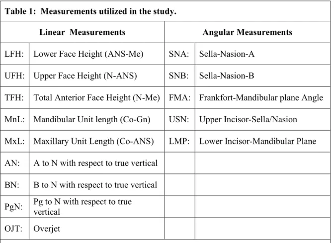
linear and five angular measurements based on sixteen landmarks (Table 1). For the
identification of the landmarks, metallic points were used in the pilot study but those
produced streaking artifacts in the synthesized cephalograms from the CBCT data and thus
made their identification difficult. Therefore the attempts were made to interpret standard
definitions of the anatomical landmarks in the conventional way and identify the landmarks
accordingly. The measurements were selected to include both vertical and antero-posterior
components of the craniofacial form. The landmarks on which these measurements were
based represented both mid-sagittal and bilateral anatomical structures with different
degrees of identification difficulty. Three linear mid-sagittal measurements were also
obtained from the skulls using a digital caliper (Absolute Digimatic No. 500-172, Mitutoyo
America Corp., Aurora, IL). The identification of mid-sagittal landmarks Nasion, Anterior
Nasal Spine, and Menton were easily identified on the skull and these landmarks gave the
three important measurements –upper face height, lower face height and the total face
height. The other mid-sagittal landmarks like point A, point B, Pogonion (Pg) and Gnathion
(Gn) are defined in a manner that their identification on the skull was not possible as the
sharp edges seen in 2D projections are replaced by surfaces and curves in the skull
The measurements were made by a single operator (VK) and repeated at three
different time points with at least one week in between. The mean of the three repeat
For the calculation of the magnification for conventional cephalograms, The source
to the patient mid-sagittal distance in the Wehmer cephalostat used was 5feet (152.40cm)
and the receptor to patient mid-sagittal distance used was 11.5cm and by computing these
values for calculating the magnification, value of 7.5% magnification was reached. The
measurements for the perspective CBCT projections were adjusted for the 7.5%
magnification. to simulate the conventional radiographs.
Statistical Analysis:
Repeated measurements were assessed by MANOVA. Averages of the 3 repeated
measurements were also assessed by MANOVA testing the radiographic modalities as
repeated measures for each measurement. Differences between midsagittal image
measurements and comparable skull measurements were analyzed with ANOVA.
Statistically significant model factors were assessed with Tukey HSD tests. The analysis
was repeated using the absolute value of the image and skull measurement difference.
Results
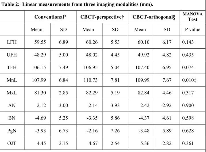
Table 2 shows the mean values for nine linear measurements from the three imaging
modalities. Differences between the modalities were not statistically significant, except for
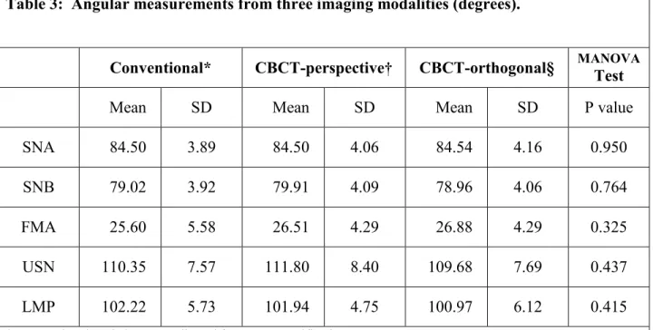
the mandibular unit length (MnL). Table 3 shows the mean values for the five angular
measurements from the three imaging modalities. None of the differences were statistically
significant. Table 4(a, b and c) shows the mean differences and the mean absolute value of
differences by midsagittal measurement and cephalometric modality. The ANOVA model
demonstrated significant differences due to image modality for both difference and absolute
value of difference. The Tukey HSD test indicated that perspective CBCT and conventional
orthogonal CBCT. Absolute value of differences between perspective CBCT and
conventional images were not significant; however, both were significantly different from
orthogonal CBCT.”
Discussion:
Lateral and frontal cephalograms together with facial photographs are currently the
main diagnostic imaging modalities for the assessment of craniofacial hard and soft tissue
morphology. The diagnostic information from these imaging modalities is considered
valuable for treatment planning, prediction of growth and treatment results and evaluation of
orthodontic and surgical outcomes. In lateral and frontal cephalograms, many structures
overlap as complex three-dimensional (3-D) structures are projected onto a two-dimensional
(2-D) plane. Moreover, the magnification and distortion inherent to conventional
transmission radiography makes it difficult to accurately assess the patient’s anatomy.11
While the potential advantages of three-dimensional CBCT imaging are evident,12, 13
quantitative assessment of the 3-D facial form requires validation through comparison with
traditional methods. Advances in CBCT imaging of the maxillofacial skeleton will be more
readily accepted by clinicians if images can be synthesized that are similar to the ones they
are familiar with and have used for several decades.
This study utilized skull measurements as the gold standard to assess the accuracy of
three mid-sagittal image measurements. The conventional imaging modality under-estimates
actual skull dimensions while the perspective CBCT over-estimates skull dimensions.
Orthogonal CBCT provided measurements closest to the actual skull measurements and was
significantly more precise than the other image modalities as assessed by the absolute
Theoretically, the magnification and distortion of perspective projection should not
affect mid-sagittal measurements. This was not the case for the current study. One possible
explanation is that the pattern of superimposing anatomy or noise differs in the conventional
and perspective projection, which may have influenced feature recognition and
measurement. The validity of this explanation is diminished by the fact that the distortion of
perspective CBCT is intended to match that of conventional cephalometric images. Another
possible explanation is that calculated magnification and actual magnification may differ in
either or both Conventional and CBCT perspective image forming techniques. Calculated
magnification is the one that calculated by computing the source to patient and patient to
receptor distances in the formula for calculating magnification that is M=SOD/SID
Actual magnification is the one determined by the reconstruction algorithm of the
Dolphin 3D pre-release version used.
The CBCT perspective reconstruction is supposed to mimic conventional
cephalograms in differential magnification of bilateral structures and magnification of the
mid-sagittal plane which is user controlled to match specific source – midsagittal plane –
image receptor geometry. While the Dolphin 3D pre-release version simulates perspective
distortion of bilateral structures, it does so while maintaining 100% magnification of the
midsagittal plane and thus does not fully simulate a conventional cephalogram which will
always exhibit a midsagittal magnification greater than 100% (7.5% - 11% typical). Another
potential source for variation in perspective CBCT cephalograms is the reference, which the
reconstruction algorithm uses for determining a midsagittal plane. If the center of the image
cephalostat is not used in CBCT imaging, the skull position may be eccentric with respect to
the volume. This potential source of measurement error was not explored in this study.
Although the skulls used in this study facilitated caliper measurement to establish
ground truth, they provide an imperfect model of radiographic imaging of patients. The
water bath used to simulate the soft tissue attenuation of x-rays for CBCT does not equate in
either quantity or distribution to the soft tissues seen in patients. Because of this, soft tissue
landmark assessment could not be carried out. Due to the use of a cylindrical container, the
volume of water in the medio-lateral dimension of the skull was disproportionately greater
than the tissue volume found in patients. The additional medio-lateral attenuation of x-rays
may have reduced the contrast of skeletal landmarks of the CBCT volume.
The results of this study also show that of the fourteen cephalometric measurements,
thirteen were not statistically different between the modalities. Ten of these measurements
were located in the midsagittal plane and four were based on bilateral landmarks.
Medio-lateral displacement from the midsagittal plane introduces the possibility of imperfect
superimposition in the lateral cephalometric image and the potential for increased variability
of landmark identification. In conventional cephalometric imaging a head-holding device,
consisting of an ear rod and nasal positioner, is used for lateral cephalometric radiographs to
minimize the projection errors caused by head rotation around the vertical, transverse, and
anteroposterior axes. Even when properly adjusted, the cephalostat cannot prevent slight
translation or rotation of the patient’s midsagittal plane. These variations in patient position
may lead to variation in cephalometric measurements. Although 3D measurements of CBCT
volumes are free from the influence of patient position during image acquisition 14, the
anatomy in synthesized 2D cephalometric views. Unlike errors in skull position seen in
conventional cephalometric images due to faulty positioning of the cephalostat or faulty
positioning of the patient within the cephalostat, orientation of the CT volume can be
corrected by iterative adjustment and reassessment. The alignment of the transporionic axis
using the 3D rendered volumes was sufficiently accurate to preclude differences in
identification and measurement of the landmarks used in this study. The ability to reorient
the volume means that cephalostat errors, common to conventional cephalometry, can be
eliminated in equivalent CBCT projections.
Differential magnification of bilateral structures as a result of a projective imaging
geometry also leads to imperfect superimposition of landmarks. This is true for conventional
cephalometric projections and perspective reconstructions of CBCT volumes. Although
measurement differences related to projective distortion of bilateral structures could be
hypothesized, no significant difference for measurements involving Condylion, Gonion,
Porion, or Orbitale were seen between Orthogonal CBCT, perspective CBCT, and
conventional cephalometric images with the exception of the mandibular unit length. This is
consistent with the observation of Lascala CA and coauthors that CBCT technique is
reliable for use in a variety of clinical situations where linear measurements between
anatomical sites are required.15
Locating 2D landmarks on complex curving structures is not a trivial problem. 16, 17.
Location of 2D landmarks on the skull and the actual 3D CBCT model still poses a
challenge. While viewing anatomy in 3 dimensions, it is evident that precise landmarks
often do not exist. The sharp edges seen in 2D projections are replaced by surfaces and
projections was often a challenge. While ear rods used in conventional cephalograms
indicate the location of the external auditory meatus, the anatomic porion is different from
the external opening. The pioneering studies of Glat 18 and Grayson 19described landmark
locations as image features but emphasized that, as a set, they constitute a stringent
abstraction from 3D image volumes. Assessment of landmark displacement is dependent on
the coordinate system used when different cephalograms are superimposed. Various authors
20, 21, 22
suggest advances towards studies of curves or surfaces in 3D, referring to tens of
thousands of 3D points to define geometry. Netherway and coauthors 23 and Schaefer and
coauthors 24 used semi-landmarks on the surface to incorporate information about deficient
direction in landmark definition into the analysis of 3D data. Richtsmeier J.T and coauthors
25
evaluated the precision and repeatability of locating anatomic landmarks in three
dimensions on CT slice.
While new methods of 3D assessment are under development, the results of this
study suggest that synthesized cephalometric images from CBCT may be used to bridge the
transition phase from 2D to 3D image analysis. Though there is stastically significant
difference between the values when the mid-sagittal measurements are compared to skull
but as those differences are very small .these are not of much clinical relevance and thus
both the projections can be used with the similar precision and accuracy as the conventional
cephalograms. Based on our results it is possible to conclude that the CBCTtechnique is
reliable for being applied at different clinicalsituations where the linear measurements
between anatomicalsites are required, such as pre-operative assessment for orthognathic
although slightly smaller,than those of real distances between skull sites, so the need for
additional conventional cephalograms is not necessary and thus patient exposure is reduced.
Further validation with patient data will be needed to confirm the reliability of
CBCT synthesized cephalograms for comparison with pre-existing cephalometric databases.
Figure 1: Orthogonal and perspective projections. Source side (S) and detector side (D) elements of a 3D object are not magnified in an orthogonal projection. In a perspective
Figure 2a
Figure 2c
Figure 2: Orthogonal CBCT projection without magnification (a); Perspective projection with 7.5% simulated magnification (b); Conventional cephalogram of skull with inherent
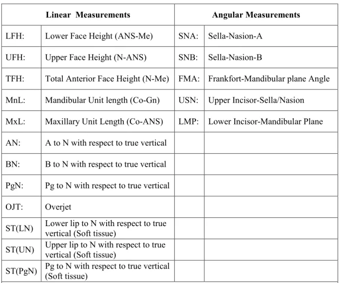
Table 1: Measurements utilized in the study.
Linear Measurements Angular Measurements
LFH: Lower Face Height (ANS-Me) SNA: Sella-Nasion-A
UFH: Upper Face Height (N-ANS) SNB: Sella-Nasion-B
TFH: Total Anterior Face Height (N-Me) FMA: Frankfort-Mandibular plane Angle
MnL: Mandibular Unit length (Co-Gn) USN: Upper Incisor-Sella/Nasion
MxL: Maxillary Unit Length (Co-ANS) LMP: Lower Incisor-Mandibular Plane
AN: A to N with respect to true vertical
BN: B to N with respect to true vertical
PgN: Pg to N with respect to true vertical
OJT: Overjet
Table 2: Linear measurements from three imaging modalities (mm).
Conventional* CBCT-perspective† CBCT-orthogonal§ MANOVATest
Mean SD Mean SD Mean SD P value
LFH 59.55 6.89 60.26 5.53 60.10 6.17 0.143
UFH 48.29 5.00 48.02 4.45 49.92 4.82 0.435
TFH 106.15 7.49 106.95 5.04 107.40 6.95 0.074
MnL 107.99 6.84 110.73 7.81 109.99 7.67 0.010‡
MxL 81.30 2.85 82.29 5.19 82.84 4.46 0.317
AN 2.12 3.00 2.14 3.93 2.42 2.92 0.900
BN -4.69 5.25 -3.35 5.86 -4.37 4.61 0.598
PgN -3.93 6.73 -2.16 7.26 -3.48 5.89 0.628
OJT 4.45 2.15 4.67 2.54 5.36 2.82 0.361
* Conventional cephalograms adjusted for 7.5% magnification
† Synthesized cone-beam CT cephalograms with perspective projection adjusted for 7.5% magnification § Synthesized cone-beam CT cephalograms with orthogonal projection
Table 3: Angular measurements from three imaging modalities (degrees).
Conventional* CBCT-perspective† CBCT-orthogonal§ MANOVA Test
Mean SD Mean SD Mean SD P value
SNA 84.50 3.89 84.50 4.06 84.54 4.16 0.950
SNB 79.02 3.92 79.91 4.09 78.96 4.06 0.764
FMA 25.60 5.58 26.51 4.29 26.88 4.29 0.325
USN 110.35 7.57 111.80 8.40 109.68 7.69 0.437
LMP 102.22 5.73 101.94 4.75 100.97 6.12 0.415
* Conventional cephalograms adjusted for 7.5% magnification
† Synthesized cone-beam CT cephalograms with perspective projection adjusted for 7.5% magnification § Synthesized cone-beam CT cephalograms with orthogonal projection
Table 4a: ANOVA Test of Actual Difference and Absolute Difference between image measurement and skull measurement of three mid-sagittal Measurements§, for three Imaging Modalities†.
P Values
Factor Tested Difference Absolute value
of difference
Measurement 0.421 0.367
Image modality 0.003† 0.007‡
Image modality*Measurement 0.191 0.582 § Measurements: LFH, UFH, TFH
† Image modalities: Conventional, CBCT-perspective, CBCT-orthogonal * Interaction term
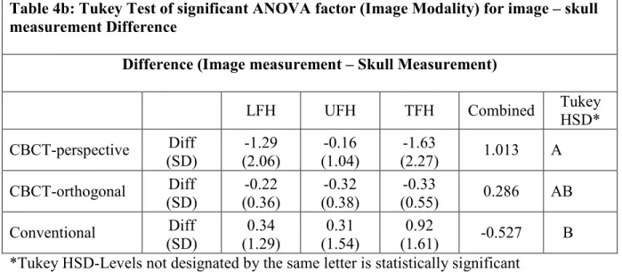
Table 4b: Tukey Test of significant ANOVA factor (Image Modality) for image – skull measurement Difference
Difference (Image measurement – Skull Measurement)
LFH UFH TFH Combined Tukey
HSD* CBCT-perspective Diff (SD) -1.29 (2.06) -0.16 (1.04) -1.63
(2.27) 1.013 A
CBCT-orthogonal Diff (SD) -0.22 (0.36) -0.32 (0.38) -0.33
(0.55) 0.286 AB
Conventional Diff (SD) 0.34 (1.29) 0.31 (1.54) 0.92
(1.61) -0.527 B *Tukey HSD-Levels not designated by the same letter is statistically significant
Table 4c: Tukey Test of significant ANOVA factor (Image Modality) for Absolute Value of image – skull measurement Difference
Absolute Value of Difference (|Image measurement – Skull Measurement|)
LFH UFH TFH Combined Tukey
HSD*
CBCT-perspective Abs Val Diff (SD) 1.36 (2.01) 0.82 (0.59) 1.63
(2.27) 1.264 A
Conventional Abs Val Diff (SD) 0.81 (1.04) 1.26 (0.85) 1.48
(1.05) 1.183 A
CBCT-orthogonal Abs Val Diff (SD) 0.34 (0.23) 0.39 (0.29) 0.38
REFERENCES
1. Ahlqvist J, Eliasson S, Welander U. The effect of projection errors on cephalometric length measurements. Eur J Orthod 1986; 8:141-148
2. Chen YJ, Chen SK, Chang HF, Chen KC. Comparison of landmark identification in traditional versus computer-aided digital cephalometry. Angle Orthod 2000; 70:387-392
3. Chen YJ, Chen SK, Huang HW, Yao CC, Chang HF. Reliability of landmark identification in cephalometric radiography acquired by a storage phosphor imaging system. Dentomaxillofac Radiol 2004; 33:301-306
4. Mah J, Hatcher D. Current status and future needs in craniofacial imaging. Orthod Craniofac Res 2003; 6 Suppl 1:10-6; discussion 179-82
5. Cavalcanti MG, Rocha SS, Vannier MW. Craniofacial measurements based on 3D-CT volume rendering: implications for clinical applications. Dentomaxillofac Radiol 2004; 33:170-176
6. Ekestubbe A, Thilander A, Grondahl K, Grondahl HG. Absorbed doses from computed tomography for dental implant surgery: comparison with conventional tomography. Dentomaxillofac Radiol 1993; 22:13-17
7. Scaf G, Lurie AG, Mosier KM, Kantor ML, Ramsby GR, Freedman ML. Dosimetry and cost of imaging osseointegrated implants with film-based and computed tomography. Oral Surg Oral Med Oral Pathol Oral Radiol Endod 1997; 83:41-48
8. Hilgers ML, Scarfe WC, Scheetz JP, Farman AG. Accuracy of linear temporomandibular joint measurements with cone beam computed tomography and digital cephalometric radiography. Am J Orthod Dentofacial Orthop 2005; 128:803-811
9. Sukovic P. Cone beam computed tomography in craniofacial imaging. Orthod Craniofac Res 2003; 6 Suppl 1:31-6; discussion 179-82
10. Ludlow JB, Davies-Ludlow LE, Brooks SL. Dosimetry of two extraoral direct digital imaging devices: NewTom cone beam CT and Orthophos Plus DS panoramic unit. Dentomaxillofac Radiol 2003; 32:229-234
11. Grayson B, Cutting C, Bookstein FL, Kim H, McCarthy JG. The three-dimensional cephalogram: theory, technique, and clinical application. Am J Orthod Dentofacial Orthop 1988; 94:327-337
13. Nakasima A, Terajima M, Mori N, et al. Three-dimensional computer-generated head model reconstructed from cephalograms, facial photographs, and dental cast models. Am J Orthod Dentofacial Orthop 2005; 127:282-292
14. Laster WS, Ludlow JB, Bailey LJ, Hershey HG. Accuracy of measurements of mandibular anatomy and prediction of asymmetry in panoramic radiographic images. Dentomaxillofac Radiol 2005; 34:343-349
15. Lascala CA, Panella J, Marques MM. Analysis of the accuracy of linear measurements obtained by cone beam computed tomography (CBCT-NewTom). Dentomaxillofac Radiol 2004; 33:291-294
16. Baumrind S, Moffitt F. Mapping the skull in 3-d. J Calif Dent Assoc 1972; 48:22-31
17. Harrell WE,Jr, Hatcher DC, Bolt RL. In search of anatomic truth: 3-dimensional digital modeling and the future of orthodontics. Am J Orthod Dentofacial Orthop 2002; 122:325-330
18. Glat PM, Freund RM, Spector JA, et al. A classification of plagiocephaly utilizing a three-dimensional computer analysis of cranial base landmarks. Ann Plast Surg 1996; 36:469-474
19. Grayson B, Cutting C, Bookstein FL, Kim H, McCarthy JG. The three-dimensional cephalogram: theory, technique, and clinical application. Am J Orthod Dentofacial Orthop 1988; 94:327-337
20. Mafart B, Guipert G, de Lumley MA, Subsol G. Three-dimensional computer imaging of hominid fossils: a new step in human evolution studies. Can Assoc Radiol J 2004;
55:264-270
21. Kragskov J, Bosch C, Gyldensted C, Sindet-Pedersen S. Comparison of the reliability of craniofacial anatomic landmarks based on cephalometric radiographs and
three-dimensional CT scans. Cleft Palate Craniofac J 1997; 34:111-116
22. Lagravere MO, Major PW. Proposed reference point for 3-dimensional cephalometric analysis with cone-beam computerized tomography. Am J Orthod Dentofacial Orthop 2005; 128:657-660
23. Netherway DJ, Abbott AH, Gulamhuseinwala N, et al. Three-Dimensional Computed Tomography Cephalometry of Plagiocephaly: Asymmetry and Shape Analysis. Cleft Palate Craniofac J 2006; 43:201-210
24. Schaefer K, Lauc T, Mitteroecker P, Gunz P, Bookstein FL. Dental arch asymmetry in an isolated Adriatic community. Am J Phys Anthropol 2006; 129:132-142
MANUSCRIPT II
In Vivo Comparison of Conventional and Cone Beam Synthesized
Abstract
OBJECTIVES: To compare measurements from synthesized cone-beam computed
tomography (CBCT) lateral cephalograms using orthogonal and perspective projections with
those from conventional cephalometric radiographs of patients.
METHODS: Thirty one patients from the UNC Dentofacial Deformities Program were
imaged using CBCT and conventional cephalometry. CBCT volume data were exported in
DICOM format and imported in Dolphin 3D. Orthogonal and perspective lateral
cephalometric radiographs were created from three dimensional (3D) virtual models. Twelve
linear and five angular measurements were made in Dolphin on synthesized and conventional
cephalograms in a randomized fashion. Perspective and conventional image measurements
were corrected for known magnification. Linear and angular measurements were compared
between image modalities using paired t-tests. Bonferroni correction for multiple
comparisons lowered the α-level to 0.003.
RESULTS: Measurements were not different between the imaging modalities (p>0.003),
except for the Frankfort-mandibular plane angle (p=0.0001). Linear measurements, whether
based on soft or hard tissue landmarks, were not statistically different.
CONCLUSIONS: Measurements from in vivo CBCT synthesized cephalograms are similar
to those based on conventional radiographic images. Thus, additional conventional imaging
may be avoided when CBCT scans are acquired for orthodontic diagnosis.
Introduction:
Cephalometry is an essential clinical and research tool in orthodontics. It continues
to be the most utilized diagnostic test to obtain absolute and relative measures of the
craniofacial skeleton and has been relied upon for decades. Lateral cephalograms are t
wo-dimensional (2D) radiographs that are used to depict three wo-dimensional (3D) structures.
Consequently, cephalograms have inherent limitations as a result of distortion and
differential magnification of the craniofacial complex. This may lead to errors of
identification and reduced measurement accuracy.1-3
Three–dimensional imaging techniques are becoming increasingly popular and have
opened new possibilities for orthodontic diagnosis, treatment assessment, and follow-up.4
Despite the usefulness and versatility of computed tomography (CT), the high cost of the
examination, limited access to scanners, and relatively high radiation exposure make this
modality unsuitable for orthodontic purposes.5 The recent introduction of maxillofacial cone
beam computed tomography (CBCT) has made 3D imaging more readily available for use in
dental applications. The major advantages of CBCT over conventional CT include low
radiation dose, lower cost, potentially better access, and high spatial resolution.6-8 While an
increasing number of applications are being described in the literature; the modality is
relatively new and requires systematic assessment to confirm its clinical usefulness.
CBCT volumes have the potential to overcome many of the limitations of conventional cephalometric imaging. However, 3D data present new challenges and need a different
approach from traditional viewing of static images to make the most of the available
information. Various techniques for the reconstruction of CT images have been used in
assessment of changes is interesting but poses many challenges. These challenges include registration and homology issues as well as the difficulty of landmark localization on anatomic surfaces. Three-dimensional landmark identification requires suitable operational
definitions of the landmark location in each of the 3 planes of space.9 While the use of 3D analysis for diagnosis and treatment undergoes clinical validation; 2D image simulation tools
may be used on 3D volumes and can help bridge the gap between 2D and 3D image types.
CBCT image data can be used to simulate panoramic, lateral, and posteroanterior
cephalometric radiographs so that they can be compared with preexisting image databases.10
Dentists have used cephalometry for more than 70 years and orthodontists have grown accustomed to using lateral radiographs for examining patients and planning treatment. As
dentistry moves from traditional 2D cephalometric analysis to new 3D techniques, it is useful
to compare 2D with 3D data. If cephalometric measurements from CBCT data are
comparable to those from traditional 2D views, patients may not need to be subjected to
further radiation exposure for the acquisition of traditional lateral cephalograms and
panoramic radiographs.
Lateral cephalometric views can be reconstructed from CBCT volumes using
orthogonal and perspective reconstructions, the latter matching the magnification and
distortion of conventional cephalograms. A previous study suggested that measurements
from CBCT synthesized cephalograms are similar to those from conventional cephalograms
in vitro.11 The purpose of this study was to determine whether CBCT synthesized cephalograms provide the same measurement accuracy and precision as conventional
cephalograms when applied to patients. The specific aims were to test the null hypotheses
synthesized CBCT cephalograms using either perspective or orthogonal reconstruction
algorithms.
Material and Methods:
Thirty-one patients (13 male, 18 female; 21.6 ± 7.9 years) treated in the Dentofacial
Deformities Program at the University of North Carolina School of Dentistry were recruited
for this study. Informed consent was obtained from all subjects and the experimental
protocols were approved by the Institutional Review Board.
Conventional cephalograms were acquired by positioning the patients in a cephalostat
in natural head position (Wehmer cephalostat, Addison, Illinois, U.S.A). The
source-midsagittal plane distance was 152.4 cm (5 feet). A photostimulable phosphor plate was used
as the detector and positioned 11.5 cm from the midsagittal plane. The plate was scanned at
300 dpi (Digora PCT, Soredex, USA).
Presurgical CBCT scans were made one week before orthognathic surgery with the
NewTom 3G (AFP Imaging, Elmsford, NY).The imaging protocol utilized a 12 inch field of
view to include the entire facial anatomy for cephalometric purposes. The “large field” and
“high resolution” options were selected for primary image reconstruction. The secondary
study data were generated such that the axial slice thickness was 0.5 mm and the voxels
isotropic. The axial images were exported in DICOM format and imported in Dolphin 3D
(pre-release version 1, Dolphin Imaging & Management Systems, Chatsworth, CA). A 3D
virtual model was created from the study (Fig.3). Using the axial view, the midsagittal plane
model was oriented horizontally. Using the sagittal view, the Frankfort horizontal plane of
the model was oriented horizontally (Fig. 4).
An “Original True Angle” angle measuring instrument (Quint Measuring Systems,
San Ramon, CA) was used to simulate the conventional cephalogram orientation (Fig. 5).
One scale of the instrument was placed parallel to the monitor screen and the other scale was
placed touching the most prominent points of the patient mid frontal bone and the mid
symphyseal region of the mandible in the conventional cephalogram. Both the scales were
affixed at that point and that angle was reproduced on the right sagittal side of the 3D virtual
model in Dolphin 3D (Fig. 6a and Fig. 6b).
Next, orthogonal and perspective radiographs were built from the reoriented model.
The orthogonal radiographs (Fig.7a) were generated with 0% magnification. An orthogonal
projection is created by parallel rays. Perspective radiographs (Fig.7b) were created
simulating the geometry of the conventional cephalometric radiographs (Fig.7c) with the
midsagittal plane of the patient at 5 feet.
Dolphin imaging software (version 9.0.00.24) was used for cephalometric tracings of
the 2D images. This study compared twelve linear and five angular measurements based on
nineteen soft and hard tissue landmarks (Table 5). The measurements were selected to
include both vertical and antero-posterior components of the craniofacial form. The
landmarks on which these measurements were based represented both mid-sagittal and
bilateral anatomical structures with different degrees of identification difficulty. The
measurements were made by a single operator (VK) in a randomized fashion. The
measurements for the perspective CBCT projections and the conventional cephalograms
Statistical Analysis:
The paired t-test was used to test the three radiographic modalities for each measurement.
Bonferroni correction for multiple comparisons was applied that lowered the alpha level for a
two-tailed t-test to 0.003.
Results:
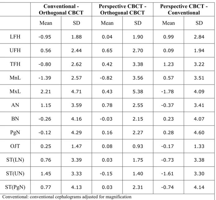
Table 6 shows the mean difference values for twelve linear measurements from the paired
comparisons of the three imaging modalities. None of the differences were statistically
significant (Table 7). Table 8 shows the mean difference values for the five angular
measurements from the three-paired comparisons of the imaging modalities. Differences
between the modalities were not statistically significant, except for Frankfort-Mandibular
plane Angle (FMA) when the adjusted conventional cephalograms were compared with the
CBCT synthesized orthogonal and the perspective projections, (Table 9).
Discussion:
Cephalometry is a valuable tool for diagnosis of skeletal imbalance, growth
assessment, response to treatment, and long term stability following orthodontic treatment.
Cephalometric evaluation of patients with orthodontic needs has traditionally been performed
by lateral and frontal cephalograms. These methods are well established and have resulted in
several large databases of normal and treated patient populations. The cephalometric analysis
is accomplished by measuring lengths and angles based on various cranio-facial hard and soft
tissue landmarks. Since standard population norms are not available for 3D CBCT volumes,
the acquisition of traditional lateral cephalograms and panoramic radiographs. Unlike
conventional cephalograms, computed tomography has no inherent distortion of anatomic
structures. As a result, more accurate measurements have been reported for planar 2D CT
images.12 The current study was undertaken to emphasize the fact that traditional
radiographic projections can be synthesized from CBCT volumes and traditional
cephalometric analysis can be done on these synthesized views with similar precision and
accuracy. While much work is needed to demonstrate the added value of CBCT in standard
orthodontic cases, it is not known whether data obtained from synthesized CBCT views can
be compared with current population norms and existing databases obtained from
conventional cephalograms. Because synthesized views discard much of the 3D information
embedded in CBCT image volumes, the demonstration of correspondence between CBCT
and conventional radiography would be useful during this transition period.
The results of this study showed that the linear measurements of the three imaging
modalities were not statistically different. All the angular measurements were also not
stastically significant except for one angular measurement that is Frankfort mandibular plane
angle (FMA). Every system has various sources of noise. In this study, only projection as the
source of noise was explored, but other sources like landmark definition, observer variability
in landmark identification and the ability to digitize the landmarks were not investigated. The
cephalometric literature reveals that the landmarks like condylion, porion and gonion, which
are used to define the Frankfort horizontal plane and the mandibular plane have, greater
margins of error.13, 14 The literature shows that superimposition of the bilateral middle ear
and other temporal fossa structures make the identification of anatomical porion difficult and
located on curved surfaces and are thus difficult to identify accurately.16 These various
sources of noise might have influenced some of the measurements.
Although FMA is defined by cephalometric landmarks menton, gonion, porion, and orbirtale,
it appears unlikely that identification of menton and gonion are responsible for the significant
difference between images seen in this study. This is because LMP, another angular
measurement dependent on the identification of menton and gonion, was not significantly
different for the different projections. Mean angular differences between techniques were less
than 1.1º for LMP while mean differences rose to 4.1º for Conventional - Orthogonal CBCT
comparisons and 4.4º for Perspective CBCT –Conventional comparisons of FMA. Because
orbitale is not usually considered a difficult-to-identify landmark, the apparent source of
variability appears to be the identification of porion. In instances where porion could not be
identified in conventional images, ear rods were used as a surrogate landmark. As the
location of the ear rods and the osseous periphery of the ear canal do not always coincide,
this may have been a source of error. While cephalostats are not used in CBCT imaging, it
would be possible to place ear plugs in the patient’s ear canals to simulate the appearance of
cephalostat ear rods.
Perspective imaging geometry leads to imperfect superimposition of bilateral
structures. This is true for conventional cephalometric projections and perspective
reconstructions of CBCT volumes. Although measurement differences related to projective
distortion of bilateral structures could be hypothesized, this study showed no significant
difference for measurements involving Condylion and Gonion between orthogonal CBCT,
observation of Lascala CA and coauthors that CBCT technique is reliable for use in a variety
of clinical situations where linear measurements between anatomical sites are required.17
The CBCT perspective reconstruction is supposed to mimic conventional cephalograms in
differential magnification of bilateral structures and magnification of the mid-sagittal plane.
This is user-controlled to match specific source–midsagittal plane–image receptor geometry.
While the Dolphin 3D pre-release version simulates perspective distortion of bilateral
structures, it does so while maintaining 100% magnification of the midsagittal plane. Thus, it
does not fully simulate a conventional cephalogram, which will always exhibit a midsagittal
magnification greater than 100% (7.5% - 11% typical). Another potential source of variation
in perspective CBCT cephalograms is the reference used to determine the midsagittal plane
for the reconstruction algorithm. The center of the image volume may not coincide with the
anatomical midsagittal plane. Because a cephalostat is not used in CBCT imaging, the patient
position may be eccentric with respect to the volume. Patient positioning is considered
critical for cephalometric analysis.18 The conventional cephalograms produced in the UNC
School of Dentistry are taken in natural head position using a cephalostat consisting of ear
rods and a nasal positioner. Natural head position is the position taken by the head when a
subject is looking at a distant point at eye level.19 The purpose of the cephalostat is to
minimize projection errors caused by head rotation around the vertical, transverse, and
anteroposterior axes. The problem usually encountered while taking the conventional
cephalogram is that even when the cephalostat is properly adjusted, it cannot prevent slight
translation or rotation of the patient’s midsagittal plane. These variations in patient position
may lead to variation in cephalometric measurements.18, 20 Although 3D measurements of
orientation of the secondary reconstruction of the volume directly impacts the projection of
anatomy in synthesized 2D cephalometric views. In order to remove potential sources of
measurement error in the synthesized views, the orientation of the CT volume was corrected
by iterative adjustment and reassessment and the natural head position was simulated by
using the angle instrument. The alignment of the transporionic axis using the 3D rendered
volumes was sufficiently accurate to preclude differences in identification and measurement
of the landmarks used in this study. The ability to reorient the volume means that cephalostat
errors, common to conventional cephalometry, can be eliminated in equivalent CBCT
projections.
Natural head position has been proposed as a reference position for assessing
craniofacial morphology, and it has been advocated as a better alternative than intracranial
reference lines because of its alleged lower variability.21Ferrario et al. observed that the soft
tissue Frankfort plane (tragus-orbitale) was not parallel to the hard tissue Frankfort plane
(porion-orbitale), the two showing a deviation of 6° on average.22 Lundström and Lundström
used tracings of the soft tissue outlines from cephalometric radiographs and measured the
inclination of the hard tissue Frankfort plane when the tracings were positioned at the natural
head position by two trained assessors. They found a slightly upward inclination of 1-2°.23
Although natural head position can be reproduced in CBCT volumes; it is debatable whether
natural head position can be produced during actual positioning of the patient during CBCT
imaging. This problem is obvious for an imaging protocol where the patient must be supine
during image acquisition. Less obvious, but still problematic is the situation where a seated
or standing patient must be stabilized in a head holder to reduce the risk of motion artifacts.
position. Alternative approaches for orienting patients’ volumes will be required in the
future. Use of defined anatomic references, such as the Frankfort plane, is an obvious
solution for standardization of images. Alternately, CT volumes may be registered with either
2D or 3D photographic images of the patient in natural head position. This type of
registration is now routinely done with CT and MR volumes.
While new methods of 3D assessment are under development, the results of this study
suggest that synthesized cephalometric images from CBCT may be used to bridge the
transition from 2D to 3D image analysis. The statistically significant difference between the
values of one of the angle measurements of synthesized projections compared to
conventional lateral views requires further investigation. Although these differences were
relatively small, they could be clinically relevant. In general, the results of this study suggest
that both types of synthesized projections can be used with a precision and accuracy similar
to conventional cephalograms and that cephalometric view generated from CBCTvolumes
may be used in place of conventional cephalometric images. If CBCT volumes are acquired,
additional conventional cephalograms should be avoided to reduce x-ray exposure and
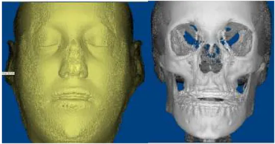
Figure3: Dolphin 3D soft and hard tissue virtual model
Figure 4: Orientation of the Dolphin 3D virtual model
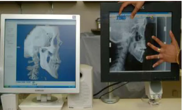
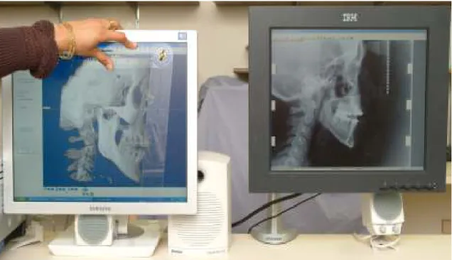
Figure 5: Angle instrument used in the study
Figure 6b: Using angle instrument to simulate the natural head position in the CBCT synthesized cephalogram
Figure 7b
Figure 7c
Figure 7: Orthogonal CBCT projection without magnification (a); Perspective projection with 7.5% simulated magnification (b); Conventional cephalogram of skull with inherent
Table 5: Measurements utilized in the study.
Linear Measurements Angular Measurements
LFH: Lower Face Height (ANS-Me) SNA: Sella-Nasion-A
UFH: Upper Face Height (N-ANS) SNB: Sella-Nasion-B
TFH: Total Anterior Face Height (N-Me) FMA: Frankfort-Mandibular plane Angle
MnL: Mandibular Unit length (Co-Gn) USN: Upper Incisor-Sella/Nasion
MxL: Maxillary Unit Length (Co-ANS) LMP: Lower Incisor-Mandibular Plane
AN: A to N with respect to true vertical
BN: B to N with respect to true vertical
PgN: Pg to N with respect to true vertical
OJT: Overjet
ST(LN) Lower lip to N with respect to true vertical (Soft tissue)
ST(UN) Upper lip to N with respect to true vertical (Soft tissue)
ST(PgN) Pg to N with respect to true vertical (Soft tissue)
Table 6: Differences between linear measurements (mm) from three imaging modalities Conventional -
Orthogonal CBCT
Perspective CBCT - Orthogonal CBCT
Perspective CBCT -Conventional
Mean SD Mean SD Mean SD
LFH -0.95 1.88 0.04 1.90 0.99 2.84
UFH 0.56 2.44 0.65 2.70 0.09 1.94
TFH -0.80 2.62 0.42 3.38 1.23 3.22
MnL -1.39 2.57 -0.82 3.56 0.57 3.51
MxL 2.21 4.71 0.43 5.38 -1.78 4.09
AN 1.15 3.59 0.78 2.55 -0.37 3.41
BN -0.26 4.16 -0.03 2.15 0.23 4.07
PgN -0.12 4.29 0.16 2.27 0.28 4.60
OJT 0.25 1.47 0.08 0.93 -0.17 1.33
ST(LN) 0.76 3.39 0.03 1.75 -0.73 3.38
ST(UN) 1.45 3.33 -0.15 1.40 -1.61 3.30
ST(PgN) 0.77 4.13 0.03 2.31 -0.74 4.14
Conventional: conventional cephalograms adjusted for magnification
Perspective CBCT: synthesized cone-beam CT cephalograms with perspective projection adjusted for magnification
Table 7: P-values from the paired t-test for the linear measurements from three imaging modalities.
Conventional - Orthogonal CBCT
Perspective CBCT - Orthogonal CBCT
Perspective CBCT -Conventional
LFH 0.01 0.91 0.06
UFH 0.21 0.19 0.81
TFH 0.10 0.49 0.04
MnL 0.01 0.21 0.37
MxL 0.01 0.66 0.02
AN 0.08 0.10 0.54
BN 0.73 0.94 0.75
PgN 0.88 0.70 0.74
OJT 0.36 0.65 0.48
ST(LN) 0.22 0.93 0.24
ST(UN) 0.02 0.55 0.01
ST(PgN) 0.31 0.94 0.33
Conventional: conventional cephalograms adjusted for magnification
Perspective CBCT: synthesized cone-beam CT cephalograms with perspective projection adjusted for magnification
Orthogonal CBCT: synthesized cone-beam CT cephalograms with orthogonal projection
Table 8: Differences between angular measurements (degrees) from three imaging modalities
Conventional - Orthogonal CBCT
Perspective CBCT - Orthogonal CBCT
Perspective CBCT -Conventional
Mean SD Mean SD Mean SD
SNA 0.91 3.06 0.35 3.31 -0.56 2.31
SNB -0.37 1.55 -0.48 1.67 -0.11 1.52
FMA 4.09 3.43 -0.27 2.27 -4.36 3.84
USN -1.29 7.49 -0.35 6.66 0.94 5.23
LMP -0.46 3.82 -1.05 2.96 -0.58 3.74
Conventional: conventional cephalograms adjusted for magnification
Perspective CBCT: synthesized cone-beam CT cephalograms with perspective projection adjusted for magnification