System Application Guide
Technical Information and
TECHNICAL APPENDIX
STRUCTURED CABLING DESIGN CONCEPT
HORIZONTAL DISTRIBUTION
APPLICATION DESIGNS
BACKBONE CABLING
CABLING SPECIFICATIONS
TECHNICAL INFORMATION & SYSTEM APPLICATION GUIDE
Table of Contents
A
B
C
D
E
F
A
Structured Cabling Design Concept
TECHNICAL INFORMATION & SYSTEM APPLICATION GUIDE
Structured Cabling
Design Concept
The Structured Cabling System plays a critical role in all telecommunication systems, providing the physical link between sources and destinations of all information. Data, voice, video and control signals are transmitted over this infrastructure linking devices across the room, throughout a building and across several buildings.
The Structured Cabling System may be quite small and simple, linking just a few nodes, or it may be massive, linking several buildings with tens of thousands of nodes, or a system somewhere in between.
Essentially the Structured Cabling System is a simple physical link between active equipment, and is comprised of Unshielded Twisted Pair (UTP) cable or Optical Fibre Cable or combinations of both. However to facilitate the day-to-day operations of a normal office environment, the link must enable the user to make adds, moves and changes wherever and whenever necessary. Furthermore, the Structured Cabling System must also be universal in its ability to carry a wide variety of applications - from voice and low speed data to high speed LAN applications, and to facilitate the migration of an organisation’s network over the life of the cabling system. Molex divides the entire system into sub-systems (horizontal, backbone, and system) and addresses each individually, which collectively forms a system that provides all of the above criteria and more. The Molex Structured Cabling System is standards based and complies with all relevant local and international telecommunications cabling standards.
The Structured Cabling System is physically configured as a Hierarchical Star, where cabling from workstations all emanate from central Floor Distributors (FD) on each floor. The Floor Distributors (FD) or Intermediate Distribution Frames (IDF) in turn, all are fed from a single Building Distributor (BD) or Main Distribution Frame (MDF), which in turn is connected back to a Campus Distributor (CD) when several buildings are interlinked.
In developing a Structured Cabling System, Molex recommends installing Unshielded Twisted Pair (UTP) cable (or Foil Screened Twisted Pair (FTP) cable where appropriate) as the horizontal connection between a work station and FD/IDF. The FD/IDF serves as a concentration point and often accommodates the active LAN switching equipment. In medium to large systems which spread across multiple floors in a building, the FD/IDF is connected via a backbone to the BD/MDF, which is the central management point of the building. The backbone generally comprises of optical fibre cabling, although voice circuits utilise UTP trunk cabling. The BD/MDF serves to interconnect between FD's/IDF's; terminal based computer systems; switch based voice communications systems; similar systems in other buildings; and the Public Switched Telephone Network (PSTN). In large systems which spread over several buildings, fibre and copper links are utilised between buildings, with all links run to a single central distribution point, the CD/CDF.
TECHNICAL INFORMATION & SYSTEM APPLICATION GUIDE
Structured Cabling
Design Concept
HORIZONTAL CABLING
Horizontal Cabling is the sub-section of the cabling system from the workstation outlet to the FD/IDF. FD's should be located so that horizontal UTP cable length is limited to 90 metres and Molex recommends that Enhanced Category 5 or higher UTP (or FTP where appropriate) be installed. This will provide compliance to industry standards design guidelines and ensures compatibility with high-speed LAN systems.
In a correctly designed horizontal cabling system, the workstation outlets in each office will be mapped to an appropriate FD. The cable run should be a direct run free of bridges, taps and splices, although industry standards will allow the introduction of a Consolidation Point (CP) in the link where appropriate.
BACKBONE
Backbone cabling provides the main feeder cable in a system. It can be either 'vertical style' in which it runs vertically between floors in a building, connecting FD/IDF's to the BD, or 'campus style' in which it connects several BD's in separate buildings to a CD/CDF in one centralised location.
Molex recommends the use of fibre optic cable in both instances although UTP (or FTP where appropriate) is used for voice applications in backbones. The fibre backbone interconnects active LAN equipment to devices situated throughout the building or campus.
FLOOR DISTRIBUTOR (FD) OR INTERMEDIATE DISTRIBUTION FRAME (IDF)
Each FD, also referred to as IDF, should be located so that the horizontal cabling length is limited to 90 metres. Generally a single FD/IDF is utilised per floor in an office environment, although several FD/IDF's will need to be established in offices with large floor areas. This ensures that all horizontal cabling to work stations is limited to no more that 90 metres.
The FD/IDF accommodates all of the cross connect facilities to interconnect work stations to active LAN equipment (also located in the FD/IDF enclosure), and backbone cabling to centralised processing equipment installed elsewhere. The FD/IDF enables office staff to conveniently make moves and changes during the course of day-to-day activities.
BUILDING DISTRIBUTOR (BD) OR MAIN DISTRIBUTION FRAME (MDF)
The BD, provides a means of centralised processing and switching systems to the vertical backbone cabling.
The backbone cabling is terminated in the BD/MDF, together with conversion of termination format where required, so that all associated cross-connects are matching.
TECHNICAL INFORMATION & SYSTEM APPLICATION GUIDE
Structured Cabling
Design Concept
DESIGNING A SYSTEM
This applications guide provides direction and ideas for designing a Molex Structured Cabling System and instructions for interfacing equipment over that system. Following this design concept section, there are a number of examples within this document of the integration of Twisted Pair and Optical Fibre cabling for specific active equipment applications, to assist in understanding the role structured cabling plays in a data network.
This section is made up of four parts; - Backbone Cabling : Fibre - Backbone Cabling : UTP/FTP - Horizontal Distribution : UTP/FTP - Horizontal Distribution : Fibre
1 - HORIZONTAL CABLING
Horizontal Cabling begins where the user plugs a terminal in and ends at a centrally located point called a Floor Distributor (FD) or Intermediate Distribution Frame (IDF). Distribution Frames should be located so that horizontal UTP/FTP* cable length is limited to 90 metres or less to provide compatibility with high-speed LAN operation. When horizontal cabling is properly designed, each office interface is accessible from an appropriate distribution frame. The cable run should be free of bridges, taps and splices.
2 - FLOOR DISTRIBUTOR OR INTERMEDIATE DISTRIBUTION FRAME Each distribution frame should be located so that the horizontal cabling length for UTP/FTP is limited to 90 metres to ensure compatibility with high-speed LAN operation. Sufficient cable management is critical for long term maintainability.
3 - BACKBONE
Backbone cabling is the main trunk cable from which all connections are made. Backbone cabling can be either “campus style,” in which it connects several buildings, or it can be run vertically between floors to connect several FD/IDF or the BD/MDF. Molex recommends the use of Optical Fibre cable, although twisted pair, or a combination of both, is acceptable. Applications include baseband LAN, broadband LAN and multiplexed channels.
4 - BUILDING DISTRIBUTOR (BD) OR MAIN DISTRIBUTION FRAME (MDF)
The BD/MDF provides a means of cross-connecting horizontal channels to equipment ports or trunk channels. The ports of each piece of system equipment need to be converted to the cross connect products mounted in the distribution frame. System Connections, Voice and LAN can be incorporated into the BD/MDF.
** NNOOTTEE :: FTP (shielded) cabling systems have traditionally been employed to take advantage of their intrinsically improved EMI (electromagnetic interference) performance. A properly installed shielded cabling system offers enhanced immunity and lower emissions than its equivalent UTP system. EMI or RFI (radio frequency interference) is any unwanted signal that adversely affects the operation of a device or system. Regulations governing emissions from and immunity to the effects of EMI (electromagnetic interference) are in force worldwide.
UTP/FTP UTP/FTP Fibre
A
1 2 4 3B
Backbone Cabling
Optical Fibre
8-11
TECHNICAL INFORMATION & SYSTEM APPLICATION GUIDE
Backbone Cabling
-Optical Fibre
OPTICAL FIBRE
Molex recommends the use of Optical Fibre as backbone cabling. Properly selected and installed Optical Fibre is the best way to ensure that the backbone will handle the traffic and provide error-free, universal data transport for the foreseeable future.
As with all other premise installations, Molex recommends a structured approach to Fibre Optic cabling. The following examples provide a guideline for implementing a structured, star-wired Fibre Optic backbone. As the “foundation” of the premise cabling system, the Fibre backbone provides:
- High performance–Gigabit per second and beyond, with the capability to handle multiple protocols on the same cable.
- Security, with centralised network control (from the BD/MDF) over the most “hard-to-tap” media available. - Dielectric data paths eliminate shielding requirements and
the need for dedicated data cable risers or conduits; correctly selected cable may be run in virtually any environment, without regard for EMI issues.
In these examples, a single Optical Fibre backbone design will be proposed for a representative four floor building. The floors are designated Ground (G), 1, 2, and 3, with the BD/MDF on the ground floor. Then, the various ways of imposing different protocols on the system will be examined, including bus, star, and token ring, without any modification of the backbone cabling. These brief examples illustrate a few of the ways in which a Fibre backbone may be used in the premises cabling to take advantage of the superior capacity, security and flexibility of optical communications.
EXAMPLE DESIGNS:
- A standard star-wired Optical Fibre building backbone design for a four floor building
- Implementation of a bus architecture (Ethernet) - Implementation of a ring architecture (FDDI) - Implementation of a hybrid (bus and ring) architecture
(Ethernet and FDDI)
- An example of a fault tolerant backbone using redundant pathways and bridges (Ethernet)
In each example, it is assumed that a 19" rack is installed in each of the four wiring closet locations–the BD or MDF and three FD or IDFs.
TECH TIP
Be aware that optic fibre standards have been revised in 2002, with ISO and AS/NZS releasing four new classifications of optical fibre, defining bandwidth and distance capabilities. These new fibre standards have been summarised in a table in the Cable and Components Specifications section of this application Guide, along with all UTP cabling standards.
B
TECHNICAL INFORMATION & SYSTEM APPLICATION GUIDE
Backbone Cabling
-Optical Fibre
EXAMPLE 1: THE STAR-WIRED OPTICAL FIBRE BACKBONE
The MDF is equipped with a Fibre Enclosure containing 72 ST® ports. Each FD/IDF contains a 24 Port ST panel. A 12-Fibre cable (six 2-12-Fibre channels) is installed from the BD/MDF to each of the three FD/IDF's. The cable is tied down to the designated area at the rear of the Fibre Enclosure using cable ties around the outer jacket, leaving 1 to 2 metres of slack cable, depending on the length required to facilitate the termination process. The Fibre Enclosure in the MDF now has three cables tied down to the back, while the 24 port fibre panel in each FD/IDF has only one cable.
After termination, the Fibre connectors should be carefully cleaned and plugged into the back of the appropriate adapter on the ST Fibre panel according to the colour code. The remaining slack is stowed into the storage clips in the 24 port fibre panel. (This is easily done by turning coils of the slack into the clips, letting the Fibre fall into its natural set). Molex recommends an intelligent numbering system based upon the destination and channel number. In the example below, the “F” prefix indicates it is a Fibre Optic cable, followed by the destination FD/IDF, then a hyphen and the channel within the cable. For example, cable F1 (Fibre Optic #1) runs from the BD/MDF to FD/IDF1 and has 6 channels, resulting in channel numbers 1-1, 1-2, 1-3, etc. For a system with two FD/IDF’s on floor 1,they could be designated IDF11 and IDF12, or IDF1E (1 East) and IDF1W (1 West). For example: The Fibres in each channel are designated “A” and “B” with “A” being “send” at the BD/MDF and “B” being “send” at the FD/IDF (“receive” at the BD/MDF), resulting in a colour code to numbering for cable 1 of:
F1-1A Dark Blue F1-1B Orange F1-2A Green F1-2B Brown F1-3A Slate F1-3B White F1-4A Red F1-4B Black F1-5A Yellow F1-5B Violet F1-6A Light Blue F1-6B Pink
Labelling should be done on the face of the patch panel.
Finally, vertical ring runs are added as appropriate, and the patch panels are labelled with the cable and channel numbers. Advantages to this design are:
- All Fibres (six pairs) are terminated and ready for use. - The building media is tied down, appropriately strain
relieved, terminated, and stored in the rear of the panel where it is protected from damage.
- Any unused Fibres are terminated and stored away from harm, but are ready for use.
- The user accesses only the patch leads, which are easily replaced if damaged.
- The system is star-wired for ease of cable documentation but can be configured into ring format (to support Token Ring or FDDI) by using patch leads.
- Any floor(s) can be bypassed or included in the backbone system from a central control point—the BD/MDF. This can be important in multi-tenancy buildings as the FD/IDF location may not be secured or accessible to the building management.
TECHNICAL INFORMATION & SYSTEM APPLICATION GUIDE
Backbone Cabling
-Optical Fibre
EXAMPLE 2: IMPLEMENTING A BUS ARCHITECTURE ON THE OPTICAL FIBRE BACKBONE
Ethernet will be used as the bus example. It is easily implemented over Fibre in a star-wired system utilising one pair of Fibres (send/receive) for each channel. The architecture uses an active Fibre switch in the BD/MDF and Fibre Optic Transceivers (FOT) in the FD/IDF's. The active Fibre switch is installed in the BD/MDF. A duplex Fibre patch lead is connected from a port on the hub to an active Fibre pair to each floor (three patch leads). This has now distributed an Ethernet signal to each floor. Generally, the Fibre switch also has an Attachment Unit Interface (AUI) port for local connection of an Ethernet repeater. If not, an independent Fibre Optic Transceiver (FOT) is connected into a spare Fibre port.
At each FD/IDF a duplex patch lead is connected from the now active Fibre pair to a FOT. This converts the optical Ethernet signal into an electronic signal on an AUI interface. Appropriate equipment for horizontal distribution of the Ethernet signal can now be connected to the backbone through the AUI ports at each floor.
Optionally, a chassis level product may be used. In this case a chassis of the appropriate size is installed into each frame (FD/IDFs and BD/MDF). In the BD/MDF chassis a multichannel Fibre card is installed into the concentrator chassis to provide the Active Fibre switch function. The most cost-effective solution at each FD/IDF is usually an independent FOT connected into the FD/IDF chassis through an AUI cable.
EXAMPLE 3: IMPLEMENTING A RING ARCHITECTURE ON THE OPTICAL FIBRE BACKBONE
Four megabit and 16 megabit Token Ring networks are easily implemented over a Fibre backbone. A newer development in token-passing technology, however, is the Class A FDDI (Fibre Distributed Data Interface) protocol. Class A FDDI is a dual counter-rotating ring topology using a token passing protocol. 100 Mbps Class “A” FDDI is most often implemented as a backbone, linking many individual LANs into a “Super LAN.” The FDDI system offers a degree of fault tolerance. If a channel is lost, whether through a failure in the media or in the transceiver electronics/optics, the equipment on each side of the failure will “loop back” its signals. This creates a single “C” shaped ring from the original “O” shaped dual rings. This technique is referred to as “self healing”’ in that a link failure in the ring will not shut the system down.
To create the FDDI ring on the Fibre backbone, an appropriate FDDI device is installed in each FD/IDF. Each of these is serviced and connected through two Fibre channels (four Fibres) back to the BD/MDF. Here another FDDI device is installed and a ring topology is created. Notice that the lower connection of the BD/MDF - FDDI device is connected through a channel to FD/IDF1 - FDDI device there. The other channel of the device in FD/IDF1 returns to the MDF through a second Optical Fibre channel where a connection is made to FD/IDF2 with a patch lead. FD/IDF2 is connected through the FDDI device back to the MDF where it connects to the FDDI device in the BD/MDF, completing the ring. This creates a star-wired Token Ring network over Optical Fibre.
Molex recommends the use of ST or SC connectors in the patch field even when the FDDI protocol is implemented. The use of ST or SC connectors will provide the following advantages:
- All of the backbone Fibres are similarly terminated, allowing the use of any Fibres for any network. - These connectors are easier to install and less expensive. - The use of ST connectors eliminates the need to
“reverse” the backbone Fibre pairs to achieve an uneven number of reversals between FDDI devices.
All reversals may be achieved by using FDDI to ST or SC patch cords to connect the devices to the backbone, with a single reversal made at the BD/MDF interconnection.
TECHNICAL INFORMATION & SYSTEM APPLICATION GUIDE
Backbone Cabling
-Optical Fibre
EXAMPLE 4: IMPLEMENTING A HYBRID ARCHITECTURE ON THE OPTICAL FIBRE BACKBONE
FDDI equipment is more expensive than the ubiquitous Ethernet equipment, so a method of implementing the FDDI network in specific applications is desirable. The lower cost and more common Ethernet system can co-exist with the FDDI system, without interfering with each other and be managed independently.
Shown here is a system based upon a high traffic level between the systems on floor 2 and the BD/MDF. An Ethernet backbone connects floors G, 1, and 3. An FDDI network connects floors G and 2, and the two systems are connected together in the BD/MDF.
Three pairs of Fibres to each floor are active, with pairs 1 and 2 as FDDI transport and pair 3 as Ethernet. This
implementation has the following features:
- Only two high-cost FDDI units are required, the remaining FD/IDF’s are serviced with relatively low-cost Ethernet. - The star-wired backbone enables floors G and 2 to be
connected without routing through any other floors, minimising the number of connections and potential failure points.
- Should traffic on other floors demand the deployment of FDDI, equipment can be easily added into the ring.
EXAMPLE 5: A FAULT TOLERANT BACKBONE USING REDUNDANT PATHWAYS AND ROUTERS
Ethernet is used for communications with a plan to provide tolerance to media faults by providing two different cable routes to each FD/IDF location. This is done by using switches and routing the cables up separate risers. The extended distance capabilities of Ethernet over Optical Fibre allows the cables to be routed through risers at opposite ends of the building, minimising the chances of communications failure due to a problem in the riser.
A router has the ability to support two different backbone Ethernets, one active and the second a live standby. If a problem occurs on the primary backbone, the routers all switch to the secondary Ethernet. In the illustration below two separate backbone systems are implemented to each FD/IDF. In the FD/IDF and the BD/MDF a router is connected with two channels, one to each backbone.
TECHNICAL INFORMATION & SYSTEM APPLICATION GUIDE
Backbone Cabling
-Copper
While most data services are LAN based and therefore utilise Optical Fibre backbones, the support of voice and low-speed legacy data systems (IBM 3270, AS400, RS232) is economically achieved on UTP.
RJ FD/IDF AND RJ BD/MDF
RJ FD/IDF AND BLOCK BD/MDF
ARCHITECTURE
Copper backbones are implemented as a star topology from a BD/MDF to a number of FD/IDF’s. Molex recommends designing the backbone as 2-pair channels; these support most voice and data applications. Optionally 3 or 4 pair channels can be implemented, but this will require more cable and, therefore, increase cost proportionally.
Molex recommends RJ-based modular patching in the FD/IDF. There are two basic design options for the BD/MDF: modular RJ patching and block-based cross connection. For RJ-based panels, there are two connecting options: mass termination through the 50 position Telco connector or KATT IDC equipped panels.
Category 3 products are recommended for most copper backbone applications since the applications running over this segment are low speed. High-speed applications such as LANs should use Optical Fibre backbones.
RJ FD/IDF AND RJ BD/MDF
In this design, patch panels are used in the FD/IDF and the BD/MDF. This is applicable to BD/MDF’s up to 1000 channels (2000 connections or three full frames). Category 3 patch panels with 50 position Telco connectors are recommended where pre-connected feeder cables are used or where the installer is set up to connect in the field. Each 25 pair group within the cable is terminated onto a 50 position Telco connector and this connector is plugged directly into the back of the patch panel.
Enhanced Category 5 or higher patch panels with KATT IDC connections are recommended where high pair count cable is used and the installer is not equipped to put 50 position Telco connectors on in the field or when such connectors would void category compliance.
These panels allow each wire of the cable to be punched down individually on the back of the panel, activating any pairs required.
RJ FD/IDF AND BLOCK BD/MDF
Molex recommends the use of blockbased cross connection systems where the number of channels to be supported exceeds 1000 channels (2000 connections or three frames) because patch cords in these larger systems can be difficult. The Molex KATT PDS system includes a patch cord which connects directly to the contact.
When patching by exception, the installer initially implements cross connections by punching down wires (generally cross connection wire) directly onto the KATT connector using a punch down tool. Since the wires are cut to exact length, the clutter is kept to a minimum. KATT patch cords are then left with the system administrator for implementing changes;
this means that any new connections are readily apparent as they have a patch cord on them. Periodically, the installer returns under a service contract to replace the patch cords with hard wiring, cleaning up the system and correcting documentation.
Molex offers two panels; both are 200 pair but with different size cable rings. The 3U panel has small rings and is applicable to Category 3 cross connection wire or an BD/MDF of one or two bays. The 4U version has larger rings for cross connection with Enhanced Category 5 or higher cable, or patch cords, or systems with three or more bays.
Several KATT connector options are available on each of the PDS panels. The pair count of the connector used on the PDS panels should match the number of channels defined by the trunk cabling. For example, if two or four pair trunk cabling is used then both the PDS panels and the patch panels should use KATT 2 or KATT 4 connectors, respectively. If 25 pair or non-defined trunk cabling is used the KATT 5 connectors should be used at both ends. This ensures that the cross-connections are made to the patch panel format and keeps the pair count consistent throughout the installation for easier system administration.
B
KATT IDC
C
Horizontal Distribution
Copper
14-15
Horizontal Distribution
-Copper
Horizontal cabling generally represents over 90% of the cable in an installation, which is a significant proportion of the cost. In addition, the horizontal cable will be concealed in the floor, ceiling, and walls making it extremely difficult and expensive to change at a later date. This means that the horizontal segment of the cabling system deserves the most attention and will take up the most design time.
TECHNICAL INFORMATION & SYSTEM APPLICATION GUIDE
UNSHIELDED/FOIL TWISTED PAIR (UTP/FTP)
Data grade UTP provides the most universal channel for data communications. It supports all common protocols and is the most economical media on a cost per metre basis. In addition to the low media cost, UTP is easily installed due to its small diameter, tight bend radius, light weight, and Insulation Displacement Contact (IDC) compatibility.
FTP has traditionally been employed to take advantage of its intrinsically improved EMI (electromagnetic interference) performance. A properly installed FTP cabling system offers enhanced immunity and lower emissions than its equivalent UTP system. EMI or RFI (radio frequency interference) is any unwanted signal that adversely affects the operation of a device or system. Regulations governing emissions from and immunity to the effects of EMI are in force worldwide.
Molex recommends using 4-pair Category 6 or Enhanced Category 5* UTP/FTP cable for all horizontal data and voice channels, making the system universal (any cable can carry either voice or data) and will facilitate data network migration.
* ISO and AS/NZS standards have dropped the term “enhanced” with Category 5. All references are to Category 5 only.
HORIZONTAL ARCHITECTURE
When specifying or designing horizontal channels the media is the most important issue even though it is not the most visible one. The quality of the cable will determine the usable life of your communications infrastructure; connections on the ends can be easily upgraded, but improving the cable requires removing it from inside the walls and ceilings.
UTP is the most universal cable for information transport, and it is important to recognise that it is also the largest installed base. This means that new communications equipment is being developed to work over this media because of that base. If the cable run distance from the closet to the work area less than 90 metres, UTP can be used. This leaves an additional 10 metres for office and closet cords. Category 6 or Enhanced Category 5 is recommended where LANs are likely to be implemented.
Use 4 pair cable, to insure the cable plant will handle new protocols, such as 1000 Base-T which uses all 4 pairs. Office outlets are chosen based upon the services required. At a minimum it requires a UTP voice channel and a UTP data channel. The specification could extend to cover additional UTP voice channels (for other lines, FAX, or modem) and spare UTP data channels (terminal, LAN). Finally, any special media channels would be specified, such as coaxial cable or optical
fibre for video or proprietary LAN cables. When an office service specification is created, it is necessary to specify the outlet packaging. This is determined by the number of channels, mounting requirements (surface, box in wall, modular furniture) and the aesthetics (colour, shape). Molex has made this easy with modular compatible products that allow protocol changes without rewiring. In the closet, the cables must be terminated in such a way that they can be attached to trunk cabling, LAN equipment, or each other. This is referred to as a “cross-connection field.” There are two major classifications of cross connection: block systems and patching systems.
Punch down blocks were developed for cross-connection of analogue voice lines to a switch. The daily changes of the system are therefore handled electronically in the switch itself, resulting in fewer “physical” moves and changes. The contacts are rated for more than 200 terminations over their life and require tooling and trained installation technicians to modify. They are, however, somewhat less expensive than RJ45 based patching initially.
Patching, on the other hand, was developed for cross-connection of data channels. The most common type of patching is “modular patching,” in which the cross-connection interface is the RJ series jack. This means that the interface is the same as that in the office, allowing the use of common patch cords and test gear. Modular patching is rated for more than 500 changes per line, and most closet equipment (i.e. LAN hubs) come with modular jack interfaces. The modular jack field acts like a telephone switchboard and can be maintained and modified by MIS personnel, lowering the life cycle cost of your installation.
Molex recommends:
- Universal channels of Category 6 or Enhanced Category 5 UTP cable (4 pair) for voice, data, and LAN - A minimum of one voice and one data channel per work
area
- At least one spare universal channel for future application - Limit the maximum horizontal cable run to 90 metres
closet to office
- Choose Category 6 or Enhanced Category 5 compliant cable, wall outlets, and patch panels
- Specify a modular patch panel as your cross connection for maintainability
EXAMPLES
As previously noted there are several options available when running UTP horizontal cabling. Cross connection can be either blocks or patching. Punch down blocks are typically used for voice. Modular IDC patching is designed for high speed data applications. Patching can be either fully assembled Insulation Displacement Contact (IDC) panels or custom configurable using configurable panels and modules.
Office outlet options depend on the services and the mounting requirements. Modules are designed to work with a variety of bezels and mountings for fixed wall, surface, modular furniture, and raised floor applications. In addition, a Multi Media Interface (MMI) box is available for mixed media and Fibre-only applications.
TECHNICAL INFORMATION & SYSTEM APPLICATION GUIDE
Horizontal Distribution
-Copper
Multi-User Telecommunications Outlet
(MUTO)
Configurable Patch Panel
PDS System
Harmonica IDC Patch Panel
Wall Plate
Surface Block
Modular Furniture Outlet
Floor Box
Multi Media Interface (MMI)
WIRING CLOSET OPTIONS
WORK AREA OPTIONS
HORIZONTAL CABLE
Refer to the Molex Product Guide for details on products shown.
LI-24 Fibre Management Panel
High Density Fibre Enclosure
USO II Wallplate
Multi Media Interface (MMI)
WIRING CLOSET OPTIONS
WORK AREA OPTIONS
HORIZONTAL CABLE
Refer to the Molex Product Guide for details on products shown.
TECHNICAL INFORMATION & SYSTEM APPLICATION GUIDE
Horizontal Distribution
-Optical Fibre
In most cases, distribution of data to the office environment, or horizontal distribution, is easily and adequately accomplished over UTP cable. Where high levels of electro-magnetic interference, extremely high data rates, signal security, or extended distances are encountered, Optical Fibre-to-the-Desk (OFTD™)1 is the perfect solution. Some factors to be considered:
- The extremely high bandwidth of Optical Fibre provides almost unlimited data capacity to the desktop for imaging, graphics transfer applications, and any other very high speed requirements.
- Fibre optic cables offer a high level of security for data. It is very difficult to “tap” an optical link.
- With the proper grade of Fibre (Refer to Optical Fibre standards table on Page 20) the maximum distance from the active equipment to the workstation may be as far as two kilometres.
There are cost factors to be considered when choosing an OFTD system. It costs little more to install Fibre cable than copper, but there is added expense in the termination of the Fibres. There are also Fibre Optic transceivers or network interface cards involved. Although the cost of these components is decreasing, they should be considered with care.
Molex recommends that horizontal cabling, in most cases, should be Category 6 or Enhanced Category 5 UTP, with Optical Fibre as the option where required for the reasons previously mentioned. A principle to consider is to find the lowest cost media type to satisfy your long term applications and environmental conditions. Note that cost considerations should not be limited to the cabling alone.
The analysis should also include the cost of the active networking equipment. Most applications, such as Gigabit Ethernet are available in many versions, dependant upon transmission media used. These different versions can vary dramatically in cost, Molex can assist you with cost models to identify the most cost effective media types for your specific requirements.
HORIZONTAL ARCHITECTURE
In the Optical Fibre to the Desk system, Fibre cables connect the distribution or interconnect unit to the wallplate or workstation. The Fibres are naturally the same as those in the vertical Fibre backbone cables, but the fibre counts are lower. Most often, two Fibre “zipcord” cables are used to feed the wallplates. These cables are small and rugged and are easily terminated. Patch cords are used to connect the active equipment to the patch panel, to connect the wall outlet to the workstation, and to cross connect in the patching field. Occasionally, single Fibre versions are used in patching. There are several connectors available for data grade Fibre. Molex recommends using MTRJ or SC type connectors in all wall plates and patch fields where possible. These types of connectors are selected because of their reliability, optical performance, and ease of installation.
In some cases, such as for FDDI applications, it may be necessary to provide an FDDI “MIC” (Media Interface Connection) at the wallplate. Here, Molex recommends the use of the SC to FDDI adapter. This device, mounted in the wallplate, uses SC connectors behind the faceplate and presents the FDDI interface to the user. (Where the Fibre backbone must be connected to an FDDI device, use an SC to FDDI patch cord.)
The office environment presents some challenges to the installation of Optical Fibre:
- Aesthetics: the outlet should look good.
- Function: the properly designed Fibre Optic outlet will have a provision for securing the incoming Fibre cable, managing an appropriate amount of Fibre slack for easy termination of the Fibre while maintaining the proper minimum bend radius.
- Capacity: the Fibre outlet must accept a sufficient number of Fibre adapters (“couplers”) to meet full application requirements with room for back up Fibres and storage for at least one metre.
- Multimedia Capability: the Fibre outlet must accept connectors for twisted pair, coax, video, and other media interconnections.
- Modularity: the outlet must be easily adapted to a variety of requirements, with easily changed connectors and adapters.
For most OFTD applications Molex recommends using angled Fibre modules to ensure correct bend radius. Molex has a number of wallplate solutions that can accommodates both Fibre and copper media and are suited for medium density applications. The Multi Media Interface (MMI) is ideally suited for high density applications requiring, any combination of Fibre, FTP or UTP connections. Both units are designed for maximum protection and proper storage of Fibre and copper media.
EXAMPLES
Interconnect and office outlet options are available when running Optical Fibre to the desktop. Configurable fibre panels and enclosures are designed for rack mount applications. The LI-24 is an enclosure that is designed for wall mount cable management.
Office outlet options depend on the services and the mounting requirements. Fibre modules are designed to work with a variety of bezels and mountings for fixed wall, surface, and raised floor applications. In addition, a Multi Media Interface is available for mixed media and high Fibre count applications.
D
Cabling Specifications
Cabling Infrastructure
18
Cables and Components
19
ISO/IEC 11801:2002 and AS/NZS 3080:2003 Standards
20
- Category 5
- Category 6
- Optical Fibre
TIA/EIA 568-B.2 Enhanced Category 5
21
TIA/EIA 568-B.2-1 Category 6
22
TIA/EIA 568-B.3 Optical Fibre
23
TECHNICAL INFORMATION & SYSTEM APPLICATION GUIDE
Cabling Specifications
-Cabling Infrastructure
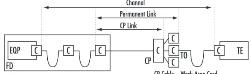
Channel
A channel is defined by ISO/IEC 11801 and AS/NZS 3080 cabling standard as: “the end-to-end transmission path con-necting any two pieces of application specific equipment. Equipment and work area cables are included in the channel.” TIA/EIA 568-B has an almost identical definition. Essentially, a channel is the entire passive cabling infrastructure between two active devices such as switches, hubs, PC’s, and printers.
The maximum permissible length of the channel is 100 metres that comprises of up to 90 metres installed permanent cable and 10 metres of interconnection cable. The interconnection cables can be fly leads at the work area, and patch cords or jumper leads at the wiring closet. The channel is defined by the Standards as having either a “cross-connect” facility with jumperable IDC’s (often referred to as a “4 connector channel model”) or an “interconnect” facility with RJ45 jacks (often referred to as a “3 connector channel model.”)
These configurations are shown in the diagrams below. Note that in both configurations, a Consolidation Point (CP) may or may not be included. Further details on CP architecture are outlined below.
Permanent Link
A Permanent Link (PL) is defined by ISO/IEC 11801 and AS/NZS 3080 cabling standards as: “the transmission path between two mated interfaces of generic cabling, excluding equipment cables, work area cables and cross connections.” Again, TIA/EIA 568-B has a similar definition. As the name suggests, this is the fixed, or permanent, part of the cabling infrastructure that is not subject to changes over the life of the cabling system. The maximum permissible length of the PL is 90 metres, and includes only the Telecommunications Outlet (TO), installed cable and the connection point that the cable is terminated on, which can be either a jumperable IDC “cross-connect” or an RJ45 patch panel “inter“cross-connect”.
By definition, the outlets are measured as “mated connections”, where the test cord plugs are inserted into the patch panel and TO jack.
Permanent Link has replaced Basic Link (BL) in both TIA and ISO standards documents. PL differs from a BL in the way field-testing is conducted. Physically these two elements are the same, however electronically, PL factors out the properties of the test cords of the tester measured in the test, whereas a BL test measures the properties of the test cords and combined them with the performance of the installed cabling.
PL is a more accurate representation of the installed cabling and should be used in specifying and testing. Make sure your field tester has PL test leads and software fitted for correct test methodology.
Note that a CP may or may not be included in a PL. Further details on CP architecture are outlined below.
Consolidation Point (CP)
A CP is defined by TIA/EIA 568-B, ISO/IEC1180 and AS/NZS 3080 cabling standard as; “A location for interconnection between horizontal cables extending from building pathways and horizontal cables extending from furniture pathways.” In other words, the cabling link between the wiring closet and work area may be broken with a secondary interconnection point in between, to enable easier rewiring of workstations as furniture is moved around.
CP must be located in a permanent part of the office, such as the services area above the ceiling or below the floor(where raised flooring is used), pillars within the office. Note that a CP is not a point of configuration, and cannot be used as a cross-connect.
Where stranded conductor cable is used from the CP to TO, the standards documents impose a 50% margin of attenuation the CP channel, since stranded conductor cable has lower performance characteristics than solid conductor cable. For example, a 2 metre stranded conductor cable is the equivalent of a 3 metre solid conductor cable. This factor must be included in the overall 100-metre length of the channel.
Figure 1 - Balanced Copper Horizontal Cabling (with Cross Connect)
Figure 2 - Balanced Copper Horizontal Cabling (with Interconnect)
Figure 3 - Channel, Permanent Link and CP Link of a Balanced Cabling
TECHNICAL INFORMATION & SYSTEM APPLICATION GUIDE
Cabling Specifications
-Cables and Components
There are three types of cables used for communications wiring: Twisted Pair, Fibre Optic, and Coaxial. Coaxial cable is not prevalent and is very application specific. Fibre Optic cables are typically used for (BD-to-FD) cabling of the vertical LAN backbone. In general, Twisted Pair (TP) is used for horizontal cabling between FD and TO and occasionally for vertical copper backbone.
Twisted Pair is available in either PVC or FRD construction. FRD construction is a fluoropolymer material such as DuPont’s Teflon. The material has low smoke/low flame
characteristics. FRD is run in forced air plenums as an alternative to conduits. PVC construction is of polyvinyl chloride material. In general, PVC is run in open air plenums or in conduits in forced air plenums.
Twisted Pair Cable — Unshielded (UTP)
UTP cable shall be Data Grade/Data Service and shall meet or exceed ISO or TIA performance requirements. It shall be bandstriped colour coded. It shall have an overall outside jacket. Conductors shall be a minimum of 0.5mm solid copper and paired with varying twist rates for each pair. Cable shall be UL or ETL verified.
Details of the TIA, ISO and AS/NZS UTP standards are listed in the following Pages 20-22.
Twisted Pair Cable — Shielded (FTP)
Specifying shielded cable is either as a means of minimising electromagnetic emissions from high speed data channels or to protect the data stream from environmental noise. As well as the many designs of cable to provide this shield there are various strategies for taking this shield to earth.
If you are considering shielded cable as part of your information transport infrastructure, Molex offers both through-shield and completely enclosed component options. Contact your Molex representative for a comprehensive design analysis and product recommendation.
Optical Fibre
Optical Fibre is being installed in more and more systems today. It is the medium of choice for backbone cabling, and has been installed directly to the workstation. It is imperative to install a quality fibre cable that offers long term utilisation and dependability.
Optical Fibre is classified by ISO into four distinct classes, determining the distance/bandwidth capabilities. These are OM1, OM2, OM3 for multimode fibre and OS1 for singlemode fibre. These classifications aid system designers when choosing which optical fibre is suitable to each application.
TECHNICAL INFORMATION & SYSTEM APPLICATION GUIDE
Cabling Specifications
-ISO/IEC 11801:2002
& AS/NZS 3080:2003
Standards
D
Frequency MHz Insrtn Loss dB NEXT dB PSNEXT dB Return Loss dB ACR dB PSACR dB ELFEXT dB PSELFEXT dB Prop Delay nsec Delay Skew nsec 1 16 100 4 9.1 24 60 43.6 30.1 57 40.6 27.1 17 17 10 56 34.5 6.1 53 31.5 3.1 57.4 33.3 17.4 54.4 30.3 14.4 580 553 548 50 50 50Enhanced Category 5 Class D Channel
Frequency MHz Insrtn Loss dB NEXT dB PSNEXT dB Return Loss dB ACR dB PSACR dB ELFEXT dB PSELFEXT dB Prop Delay nsec Delay Skew nsec 1 16 100 4 7.7 20.4 60 45.2 32.3 57 42.2 29.3 19 19 12 56 37.5 11.9 53 34.5 8.9 58.6 34.5 18.6 55.6 31.5 15.6 521 496 491 44 44 44
Enhanced Category 5 Class D Permanent Link
Frequency MHz Insrtn Loss dB NEXT dB PSNEXT dB Return Loss dB FEXT dB PSFEXT dB Prop Delay nsec Delay Skew nsec TCL db 1 100 0.1 0.4 80 43 77 40 30 20 65 35.1 62 32.1 2.5 2.5 1.25 1.25 60 26
Enhanced Category 5 Connecting HardWare
Frequency MHz Insrtn Loss dB NEXT dB PSNEXT dB Return Loss dB ACR dB PSACR dB ELFEXT dB PSELFEXT dB Prop Delay nsec Delay Skew nsec 1 16 100 250 4 8.3 21.7 35.9 65 53.2 39.9 33.1 62 50.6 37.1 30.2 19 18 12 8 61 44.9 18.2 -2.8 58 42.3 15.4 -5.8 63.3 39.2 23.3 15.3 60.3 36.2 20.3 12.3 580 553 548 546 50 50 50 50
Category 6 Class E Channel
Frequency MHz Insrtn Loss dB NEXT dB PSNEXT dB Return Loss dB FEXT dB PSFEXT dB Prop Delay nsec Delay Skew nsec TCL db 1 100 250 0.1 0.2 0.32 80 54 46 77 50 42 30 24 16 65 43.1 35.1 62 40.1 32.1 2.5 2.5 2.5 1.25 1.25 1.25 60 26 18
Category 6 Connecting HardWare
Frequency MHz Insrtn Loss dB NEXT dB PSNEXT dB Return Loss dB ACR dB PSACR dB ELFEXT dB PSELFEXT dB Prop Delay nsec Delay Skew nsec 1 16 100 250 4 7.1 18.5 30.7 65 54.6 41.8 35.3 62 52.2 39.3 32.7 21 20 14 10 61 47.5 23.3 4.7 58 45.1 20.8 2.0 64.2 40.1 24.2 16.2 61.2 37.1 21.2 13.2 521 496 491 490 44 44 44 44
Category 6 Class E Permanent Link
Applications OM1 (Multimode Fibre) OM2 (Multimode Fibre) OM3 (Multimode Fibre) OS1 (Singlemode Fibre) 500m 300m -220-275m -500m -2000m 2000m -550m 300m -500m 500m -500-550m -500m -2000m 2000m -550m 300m -500m 500m -500m -300m 500m -2000m 2000m -550m 300m -2000m 2000m -5000m -Optical Fibre ATM 622 Mbps Fibre Channel 1062 Mbps FDDI 100 Base-FX Ethernet 1000 Base-SX Ethernet 1000 Base-LX Ethernet 10G Base-LX4 Ethernet 10G Base-SR/SW Ethernet 850 nm 1300 nm 850 nm 1300 nm 850 nm 1300 nm 1310 nm 1550 nm
1 10 20 25 31.3 62.5 100 65 63 57 55 53.1 47.1 43 65 55.1 49.1 47.1 45.2 39.2 35.1 30 30 30 30 30 24.1 20 0.10 0.10 0.20 0.20 0.20 0.30 0.40
TECHNICAL INFORMATION & SYSTEM APPLICATION GUIDE
Enhanced Category 5 Propagation Delay
- Channel : Shall not exceed 555 nano Seconds @ 10MHz - Link : Shall not exceed 498 nano Seconds @ 10MHz
Enhanced Category 5 Delay Skew
- Channel : Shall be less than 50 nano Seconds - Link : Shall be less than 44 nano Seconds
D
Cabling Specifications
-TIA/EIA 568-B.2-1
Category 5
Frequency
MHz NEXTdB PSNEXTdB ELFEXdB PSELFEXTdB Return LossdB Insertion LossdB
1 10 20 25 31.3 62.5 100 60 47 42 40.3 38.7 33.6 30.1 57 44 39 37.3 35.7 30.6 27.1 57.4 37.4 31.4 29.4 27.5 21.5 17.4 54.4 34.4 28.4 26.4 24.5 18.5 14.4 17 17 17 16 15.01 12.01 10 2.2 7.1 10.2 11.4 12.9 18.6 24
Enhanced Category 5 Channel
Enhanced Category 5 Propagation Delay
- Channel : Shall not exceed 555 nano Seconds @ 10MHz - Link : Shall not exceed 498 nano Seconds @ 10MHz
Enhanced Category 5 Delay Skew
- Channel : Shall be less than 50 nano Seconds - Link : Shall be less than 44 nano Seconds Frequency
MHz NEXTdB PSNEXTdB ELFEXTdB PSELFEXTdB Return LossdB Insertion LossdB
1 10 20 25 31.3 62.5 100 60 48.5 43.7 42.1 40.5 35.7 32.3 57 45.5 40.7 39.1 37.5 32.7 29.3 58.6 38.5 32.6 30.7 28.7 22.7 18.6 55.6 35.6 29.6 27.7 25.7 19.7 15.6 19 19 19 18 17.1 14.1 12 2.1 6.2 8.9 10 11.2 16.2 21
Enhanced Category 5 Permanent Link
Frequency
MHz NEXTdB PSNEXTdB ELFEXTdB PSELFEXTdB Return LossdB Insertion LossdB
1 10 20 25 31.3 62.5 100 65.3 50.3 45.8 44.3 42.9 38.4 35.3 62.3 47.3 42.8 41.3 39.9 35.4 32.3 63.8 43.8 37.7 35.8 33.9 27.9 23.8 60.8 40.8 34.8 32.8 30.9 24.9 20.8 20 25 25 24.32 23.64 21.54 20.11 2 6.5 9.3 10.4 11.7 17 22
Enhanced Category 5 Cable
Frequency
MHz NEXTdB FEXTdB Return LossdB Insertion LossdB Enhanced Category 5 Connecting Hardware
Frequency
MHz Return LossdB Insertion LossdB
1 10 20 25 31.3 62.5 100 20 25 25 24.2 23.3 20.7 19 2.4 7.8 11.1 12.5 14.1 20.4 26.4
Enhanced Category 5 Stranded Cable
Frequency
MHz Return LossdB 2m LengthNext dB 5m LengthNext dB 10m LengthNext dB
1 10 20 25 31.3 62.5 100 19.8 22.8 23.7 24 23 20 18 65 54.5 48.6 46.7 44.8 39 35.1 65 53.7 47.9 46 44.2 38.5 34.8 65 52.8 47.1 45.3 43.6 38.1 34.6
TECHNICAL INFORMATION & SYSTEM APPLICATION GUIDE
Cabling Specifications
-TIA/EIA 568-B.2-1
Category 6
D
Frequency
MHz NEXTdB PSNEXTdB ELFEXTdB PSELFEXTdB Return LossdB Insertion LossdB
1 10 20 62.5 100 200 250 65 56.6 51.6 43.4 39.9 34.8 33.1 62 54 49 40.6 37.1 31.9 30.2 63.3 43.3 37.2 27.3 23.3 17.2 15.3 60.3 40.3 34.2 24.3 20.3 14.2 12.3 19 19 17.5 14 12 9 8 2.1 6.3 9 16.5 21.3 31.5 35.9 Category 6 Channel Frequency
MHz NEXTdB PSNEXTdB ELFEXTdB PSELFEXTdB Return LossdB Insertion LossdB
1 10 20 62.5 100 200 250 65 57.8 53.1 45.1 41.8 36.9 35.3 62 55.5 50.7 42.7 39.3 34.3 32.7 64.2 44.2 38.2 28.3 24.2 18.2 16.2 61.2 41.2 35.2 25.3 21.2 15.2 13.2 19.1 21 19.5 16 14 11 10 1.9 5.5 7.9 14.4 18.6 27.4 31.1
Category 6 Permanent Link
Frequency MHz NEXT dB PSNEXT dB ELFEXT dB PSELFEXT dB Return Loss dB Insrtn Loss dB Prop Delay (nS/100m) LCL dB LCTL dB Return Loss dB Insrtn Loss dB 1 10 20 62.5 100 200 250 74.3 59.3 54.8 47.4 44.3 39.8 38.3 72.3 57.3 52.8 45.4 42.3 37.8 36.3 67.8 47.8 41.8 31.9 27.8 21.8 19.8 64.8 44.8 38.8 28.9 24.8 18.8 16.8 20 25 25 21.5 20.1 18 17.3 2 6 8.5 15.4 19.8 29 32.8 570 545 538 536 40 40 37 32 30 27 26 TBD TBD TBD TBD TBD TBD TBD 20 25 25 20.7 19 16.4 15.6 2.4 7.1 10.2 18.5 23.8 34.8 39.4
Category 6 Cable - 100m Cat 6 Stranded Cable
Frequency
MHz NEXTdB Return LossdB NEXT (5m)dB NEXT (10m)dB LCLdB LCTLdB
1 10 20 62.5 100 200 250 19.8 22.8 23.7 20 18 15 14 65 65 60.1 50.4 46.4 40.6 38.8 65 64.5 58.6 49.2 45.3 39.8 38.1 65 62.9 57.2 48.1 44.4 39.3 37.6 40 40 37 32 30 27 26 TBD TBD TBD TBD TBD TBD TBD
Category 6 Patch Cord
Frequency
MHz Insertion LossdB NEXTdB FEXTdB Return LossdB LCLdB LCTLdB
1 10 20 62.5 100 200 250 0.10 0.10 0.10 0.16 0.20 0.28 0.32 75 74 68 58.1 54 48 46 75 63.1 57.1 47.2 43.1 37.1 35.1 30 30 30 28.1 24 18 16 40 40 40 32.1 28 22 20 TBD TBD TBD TBD TBD TBD TBD
Category 6 Connecting Hardware
- Propagation delay for Connecting Hardware not to exceed 2.5nS. Delay skew for each mated connection shall not exceed 1.25nS
- Propagation delay for Channel shall be less than 555nS measured at 10MHz. Max delay skew for a channel shall be less than 50nS
- Propagation delay for permanent link shall be less than 498nS measured at 10MHz. Max delay skew for a permanent link shall not exceed 44nS. The difference in propagation delay in a cable shall not exceed 45 ns/100m between 1 MHz and 250 MHz
TECHNICAL INFORMATION & SYSTEM APPLICATION GUIDE
Cabling Specifications
-TIA/EIA 568-B.3
Optical Fibre
D
Cable Type Wavelength (nm)
Maximum Attenuation (dB/km)
Maximum Information Transmission Capacity (MHz.km)
Optical Fibre
50/125µm 62.5/125µm
Singlemode Inside Plant Cable
Multimode Inside Plant Cable
850 1300 850 1300 1310 1500 1310 1500 3.5 1.5 3.5 1.5 1.0 1.0 0.5 0.5 500 500 160 500 NA NA NA NA
TECHNICAL INFORMATION & SYSTEM APPLICATION GUIDE
Cabling Specifications
-Cable Safety Ratings
The cabling industry is heavily regulated for both transmission performance and safety. Safety in cabling is vitally important, and has been extensively documented by standards bodies and industry groups around the world.
One of the most widely recognised authority on cabling safety is Underwriters Laboratories (UL), a not-for-profit organisation committed to establishing and maintaining safety criteria for many industries.UL offer a number of qualification services to the cabling industry.
These include:
- UL Listing – qualifying the safety rating of cable and associated hardware.
- UL Verification – qualifying the transmission performance of cabling to the performance specifications outlined in TIA/EIA cabling standards, as well as safety ratings; and maintained on a regular basis with quality assurance monitoring and un-announced factory inspections.
UL Communications Cabling
UL classifies cabling used for voice and data systems as “Communications Wires and Cables”, abbreviated as CM. Within this classification are several safety ratings for specific applications that qualify the jacket of a cable, see table below.
Plenum rated communications cable. This is the highest safety rating for cable with excellent flame retardancy and low smoke and toxin emission. By UL definition, a bundle of CMP cables must self-extinguish with less than 5 metres of flame spread under intense fan-forced flame conditions. CMP cable uses Teflon-based chemicals to retard the spread of flames, with minimal smoke and toxin emission. This adds considerable cost over lower UL rated cables. CMP rated cable is used in buildings where the cable is routed in the ventilation return air path. In the event of fire, there is no smoke or dangerous toxin emission to be pumped through the building. This style of return air reticulation is used extensively in the USA, but rarely used elsewhere in the world. CMP rated cable is subjected to severe flame testing, UL910 – “Tests for flame- propagation and smoke-density values”
Riser rated communications cable. This is the next highest rating cable with excellent flame retardancy, but no qualification on smoke or toxin emission. CMR cables, like all other communications cables, with the exception of CMP rated cables, use halide-based chemicals, such as chlorine, to retard the spread of flames. By definition, a CMR cable must self-extinguish with less than 5 metres of flame spread, in bundles of cables under fan-forced flame conditions. A CMR cable jacket would typically be made of a type of PVC, which emits chlorine gas when subjected to flames, which subsequently starves the air of oxygen and extinguishes the flame. CMR rated cables are used extensively in riser applications where the ventilation system is physically separate from the cabling system. This is very common in Asia and Australia. CMR rated cable is subjected to intense flame testing, UL1666 – “Test for flame propagation heights of cables installed vertically in shafts”.
General Purpose communications cable. This is commonly used in buildings for horizontal runs, usually in smaller bundles than CMR rated cables. CM/CMG rated cables use halide-based chemicals for fire retardancy. By definition, a CM/CMG cable must self-extinguish with less than 5 metres of flame spread in small bundles of cables. The flame is not fan-forced. A CM/CMG rated cable jacket would typically be made of a type of PVC, which emits chlorine gas when burned. CM/CMG rated cables are commonly used for horizontal runs in the UK, Asia and Australia. CM/CMG rated cables are subjected to CSA FT-4 “Vertical Flame Test”.
Communications Cable for Dwellings. This cable is restricted for use in dwellings or other small applications where a very small number of communications cables are used, typically in single cable runs. The CMX rating does not provide for bundled cable applications. Molex Premise Networks strongly recommends that CMX cables not be installed in any commercial premises. In fact, some government building regulations do not allow CMX cable to be used in commercial premises. CMX rated cable is subjected to UL VW1 Flame Test.
CMP
CMR
CM/CMG
CMX
UL have a separate classification system for optical fibre systems, similar to the Communications Cabling Safety System. A further classification of “metallic” and “non-metallic” construction is also introduced. The jacket flame/emission rating is the same as for copper cables:
Fibre Cable containing no metallic elements
- OFNP – Plenum rated nonconductive optical fibre cable - OFNR – Riser rated nonconductive optical fibre cable - OFN/OFNG – General rated nonconductive optical fibre cable
Fibre Cable containing metallic elements - OFCP – Plenum rated conductive optical fibre cable - OFCR – Riser rated conductive optical fibre cable - OFC/OFCG – General rated conductive optical fibre cable
Low Smoke Zero Halogen (LSZH)
Another safety rating used in the cabling industry is Low Smoke Zero Halogen (LSZH). The rating is classified by ISO/IEC standards and used extensively in Europe. LSZH rating, like UL CMP rating, qualifies both flame retardancy and gas emission. As the name suggests, a burning LSZH gives off no halide gases, and has very low smoke emission.
LSZH rated cables are available for both copper and optical fibre communications cables, and structured in a similar manner to UL ratings.
E
Application Designs
10 Base-T Ethernet - Modular
26
10 Base-T Ethernet - 25 Pair
27
100 Base-T4 Ethernet (Fast Ethernet)
28
100 Base-TX Ethernet (Fast Ethernet)
29
1000 Base-T Ethernet (Gigabit Ethernet)
30
1000 Base-FX Ethernet (Gigabit Ethernet)
31
ATM (Asynchronous Transfer Mode) - Unshielded Twisted Pair
32
ATM (Asynchronous Transfer Mode) - Optical Fibre
33
FDDI TP-PMD
34
IBM AS400/System 3X
35
IBM 3270
36
RS232
37
Terminal Servers
38
Token Ring
39
TECHNICAL INFORMATION & SYSTEM APPLICATION GUIDE
Application Designs
10 BaseT Ethernet
-Modular
Ethernet has become the world’s de-facto local area networking standard. According to several recent market research reports, over 90% of all networked devices in the world were linked over Ethernet of one sort or another. The Ethernet LAN standard is defined by the Institution of Electrical and Electronic Engineers (IEEE), covering protocol, architecture, migration strategy, and media types. There are many versions of Ethernet available, offering data throughput rates of 10 Mbps, 100 Mbps, 1000 Mbps and 10 Gbps, each of which can be deployed over a variety of media types, some of which are coax, UTP, STP and optical fibre.
The Ethernet protocol can be broken up into 2 distinct parts – media independent and media dependant.The media independent part is concerned with complex signalling, addressing and management, but isn’t concerned with what media it is interfaced with. The Media dependant part deals with conditioning the Ethernet signal to transmitting or receiving over a specific media type, optimising the signal throughput.
Ethernet has remained popular as a network protocol for many reasons, but one important reason is its heterogeneous application, and simple migrating paths. Various versions of Ethernet can co-exist in a network, and intelligent switching devices can actually determine the optimum speed at which to transmit. The migration to higher data speeds is also facilitated in the overall Ethernet design principle. The most common form of Ethernet is 10 Base-T, which delivers 10 Mbps over UTP cabling, and can be configured with modular-based interconnection or with telco-based interconnection.
The diagram below illustrates the structure for a modular based system. 10 Base-T Ethernet can be supported by a Category 3, 4, 5, 5e or 6 UTP cabling infrastructure, as the bandwidth requirement is minimal. Molex recommends installing Category 5e cabling as a minimum, to facilitate simple network migration to high-speed versions of Ethernet, such as Gigabit Ethernet, which requires Enhanced Category 5 cabling as a minimum.
IEEE 802.3:2000 10 Base-T Channel Specification
Insertion Loss < 11.5 dB @ 10 MHz NEXT > 26 dB @ 10 MHz PSNEXT * > 23 dB @ 10 MHz
BER < 10 -8
Encoding System Manchester Active Pins 1&2, 3&6 * Based on 4 pair cable
Item No. Description
1 10 Base-T Ethernet Switch - Customer Supplied
2 UTP Patch Cord, Cat 5e - Molex
3 Patch Panel, Cat 5e - Molex
4 UTP Cable, Cat 5e - Molex
5 Jack & Wallplate, Cat 5e - Molex
6 UTP Patch Cord, Cat 5e - Molex
7 Work Station - Customer Supplied
APPLICATION KEY
1 2 3 4 5 6 7E
Item No. Description
1 10 Base-T Ethernet Switch - Customer Supplied 2 Telco Feeder Cable, Cat 5 (100 Base-T) - Molex 3 24 Port Telco Patch Panel, Cat 5 (100 Base-T) - Molex
4 UTP Patch Cord, Cat 5e - Molex
5 Patch Panel, Cat 5e - Molex
6 UTP Cable, Cat 5e - Molex
7 Jack & Wallplate, Cat 5e - Molex
8 UTP Patch Cord, Cat 5e - Molex
9 Work Station - Customer Supplied
TECHNICAL INFORMATION & SYSTEM APPLICATION GUIDE
Application Designs
10 BaseT Ethernet
-25 Pair
APPLICATION KEY
A number of 10 Base-T Ethernet switches and hubs utilise Telco, or 25 pair, connectors for connectivity instead of modular RJ45 connectors. This affords a higher density of ports on the active equipment.
This method of interconnection is recognised by IEEE 802.3 as an approved format for Ethernet.
The illustration below outlines one application of a switch with front-facing Telco connectors. The same design applies to switches with rear-facing Telco connectors. In this application, a second patching facility from the switch is provided through a Telco cable and Telco patch panel, to enable simple modular patching from the switch to the drop-side cabling.
The Telco version of 10 Base-T can be supported with Category 3 Telco feeder cables and patch panels, however Molex recommends installing PowerSum rated Category 5 feeder cabling and Telco panels as a minimum, to facilitate effective network migration to high-speed versions of Ethernet which use Telco interconnections, such as Fast Ethernet
(100 Base-T), that requires Category 5 cabling as a minimum.
IEEE 802.3:2000 10 Base-T 25 Pair Channel Specifications
Insertion Loss < 11.5 dB @ 10 MHz NEXT > 26 dB @ 10 MHz PSNEXT * > 30 dB @ 10 MHz
BER < 10 -8
Encoding System Manchester Active Pins 1&2, 3&6 * Based on 4 pair cable
1 2 3 4 5 6 7 8 9
E
TECHNICAL INFORMATION & SYSTEM APPLICATION GUIDE
Application Designs
100 Base-T4 Ethernet
(Fast Ethernet)
APPLICATION KEY
100 Base-T4 Ethernet is also known as Fast Ethernet, which transmits data at 100 Mbps. It is the next step up from 10 Base-T in the Ethernet hierarchy as defined by IEEE 802.3. Unlike 100 Base-TX which transmits signals over 2 pairs, this application transmits over all 4 pairs of the cabling. 100 Base-T4 introduced a new method of signal transmission, generically known as a Parallel Transmission Scheme. The media independent signal at the transmitter (near end) is split into four parts and each transmitted down a specific pair in the cable, and reassembled at the receiver (far end). At the same time, signals from the far end are transmitted to the near end, yielding full duplex transmission at 100 Mbps. Essentially this enables more Mbps to be extracted per MHz. 100 Base-T4 has a data throughput of 100 Mbps, but a centre frequency of transmission of 33.33 MHz.
Simultaneous transmission of signals over all four pairs incurred the cumulative effect of cross-talk between all the pairs in the cable, as they all carry signals at the same time, and can interfere with each other. Thus, a powersum rating of cross-talk had to be introduced to cabling specifications. Additionally, simultaneous transmission of signals from both ends raised the need to qualify the cross-talk at both the near and far ends. Therefore, far end cross talk (FEXT) was added to the cabling specifications.
The minimal cabling performance requirement for 100 Base-T4 is therefore Enhanced Category 5.
IEEE 802.3:2000 100 Base-T4 Channel Specifications Insertion Loss < 12 dB @ 12.5 MHz NEXT > 24.5 dB @ 12.5 MHz PSNEXT > 21.4 dB @ 12.5 MHz ELFEXT > 23.1 dB @ 12.5 MHz PSELFEXT > 20.9 db @ 12.5 MHz BER < 10 -8
Encoding System Ternary 8B6T Active Pins 1&2, 3&6, 5&4, 7&8
Item No. Description
1 100 Base-T Ethernet Switch - Customer Supplied 2 UTP Patch Cord, Cat 5e or Cat 6 - Molex 3 Patch Panel, Cat 5e or Cat 6 - Molex
4 UTP Cable, Cat 5e or Cat 6 - Molex
5 Jack & Wallplate, Cat 5e or Cat 6 - Molex 6 UTP Patch Cord, Cat 5e or Cat 6 - Molex
7 Work Station - Customer Supplied
1 2 3 4 5 6 7
E
TECHNICAL INFORMATION & SYSTEM APPLICATION GUIDE
Application Designs
100 Base-TX Ethernet
(Fast Ethernet)
APPLICATION KEY
100 Base-TX Ethernet is also known as Fast Ethernet, which transmits data at 100 Mbps. It too is the next step up from 10 Base-T in the Ethernet hierarchy as defined by IEEE 802.3. Unlike 100 Base-T4, which transmits signals over 4 pairs; this application transmits over 2 pairs of the cabling.
100 Base-TX is similar to the transmission process of 10 Base-T. The signal is transmitted in its entirety down one pair, and received in the same manner over another pair. The two unused pairs carry no signals. There are no sophisticated encoding system to extract more Mbps per MHz. 100 Base-TX has a data throughput of 100 Mbps, and a centre frequency of transmission of 100 MHz. This relatively simple protocol does not impose any additional cable parameters above those specified by Category 5.
However Molex recommends installing Enhanced Category 5 cabling as a minimum for this application, to facilitate migration of the network to other versions of ethernet, such as Gigabit Ethernet. IEEE 802.3:2000 100 Base-TX Channel Specifications Insertion Loss < 12 dB @ 12.5 MHz NEXT > 24.5 dB @ 12.5 MHz BER < 10 -12 Encoding System MLT-3 Active Pins 1&2, 3&6
Item No. Description
1 100 Base-T Ethernet Switch - Customer Supplied 2 UTP Patch Cord, Cat 5e or Cat 6 - Molex 3 Patch Panel, Cat 5e or Cat 6 - Molex
4 UTP Cable, Cat 5e or Cat 6 - Molex
5 Jack & Wallplate, Cat 5e or Cat 6 - Molex 6 UTP Patch Cord, Cat 5e or Cat 6 - Molex
7 Work Station - Customer Supplied
1 3 4 6 7
E
WIRING CLOSET WORK AREA
5 2
TECHNICAL INFORMATION & SYSTEM APPLICATION GUIDE
Application Designs
1000 Base-T Ethernet
(Gigabit Ethernet)
1000 Base-T Ethernet is also known as Gigabit Ethernet, which transmits data at 1000 Mbps, or 1 Gbps. It is the next step up from 100 Base-T in the Ethernet hierarchy as defined by IEEE 802.3. 1000 Base-T transmits signals over all 4 pairs of the cabling.
Like 100 Base-T4 Fast Ethernet, 1000 Base-T Gigabit Ethernet deploys a new method of signal transmission, generically known as a Parallel Transmission Scheme. The media independent signal at the transmitter (near end) is split into four parts and each transmitted down a specific pair in the cable, and reassembled at the receiver (far end). At the same time, signals from the far end are transmitted to the near end, yielding full duplex transmission at 1000 Mbps. 1000 Base-T has a data throughput of 1000 Mbps, but a centre transmission frequency of 62.5 MHz.
Simultaneous transmission of signals over all four pairs incurred the cumulative effect of cross-talk between the all pairs in the cable, as they all carry signals at the same time, and can interfere with each other. Thus, a powersum rating of cross-talk had to be introduced to cabling specifications. Additionally, simultaneous transmission of signals from both ends raised the need to qualify the cross-talk at both the near and far ends. Therefore, far end cross talk (FEXT) was added to the cabling specifications.
The minimal cabling performance requirement for 1000 Base-T is therefore today’s Category 5.
IEEE 802.3:2000 1000 Base-T Channel Specifications Insertion Loss < 24 dB @ 100 MHz NEXT > 30.1 dB @ 100 MHz PSNEXT >27.1 dB @ 100 MHz ELFEXT > 17.4 dB @ 100 MHz PSELFEXT > 14.4 dB @ 100 MHz Return Loss > 8 dB @ 100 MHz Delay < 570n Sec @ 100 MHz Delay Skew < 50n Sec @ 100 MHz BER < 10 -10
Encoding System PAM5
Active Pins 1&2, 3&6, 5&4, 7&8
APPLICATION KEY
Item No. Description
1 Ethernet Switch with Gigabit Ethernet Modules - Customer Supplied 2 UTP Patch Cord, Cat 5e or Cat 6 - Molex
3 Patch Panel, Cat 5e or Cat 6 - Molex
4 UTP Cable, Cat 5e or Cat 6 - Molex
5 Jack & Wallplate, Cat 5e or Cat 6 - Molex 6 UTP Patch Cord, Cat 5e or Cat 6 - Molex
7 Work Station - Customer Supplied
1 2 3 4 6 7
E
WIRING CLOSET WORK AREA