Operating Instructions
OI/TTF300-EN
Field mounted Temperature Transmitters
TTF300
Field mounted Temperature Transmitters
TTF300
Operating Instructions
OI/TTF300-EN05.2006
Manufacturer:
ABB Automation Products GmbH
Borsigstraße 2 63755 Alzenau Germany
Tel.: +49 551 905-534 Fax: +49 551 905-555
© Copyright 2006 by ABB Automation Products GmbH Subject to change without notice
This document is protected by copyright. It assists the user with the safe and efficient operation of the device. The contents may not be copied or reproduced in whole or in excerpts without prior approval of the copyright holder.
1 Safety...6
1.1 General Safety Information ...6
1.2 Intended use...6
1.3 Technical limits...6
1.4 Warranty provision ...7
1.5 Labels and symbols...7
1.5.1 Symbols and warnings ...7
1.5.2 Name plate...8
1.6 Operator liability ...8
1.7 Personnel qualification ...8
1.7.1 Returning devices ...9
1.8 Transport safety information ...9
1.9 Electrical installation safety information ...9
1.10 Operating safety information ...9
2 Use in areas requiring ignition protection ...10
2.1 Approvals ...10
2.2 Ground...10
2.3 Interconnection...10
2.4 Configuration ...10
2.5 Explosion-protection relevant information ...10
3 Design and function ...11
4 Installation...12
4.1 Installation options...12
4.1.1 Wall installation ...12
4.1.2 Pipe installation ...13
4.2 Installing the LC display with control buttons ...14
5 Electrical connection ...15
5.1 Conductor material ...15
5.2 Connection for power supply cable ...16
5.4.9 Hermetically sealed zone 0 ...30
6 Start-up...31
7 Configuration ...31
7.1 Configurations ...31
7.1.1 HART communication ...31
7.1.2 Configuration via the LCD display with the control buttons ...32
7.1.3 Configuration with the handheld terminal...32
7.1.4 Configuration with SmartVision...32
7.2 Configuration via the LCD display and the control buttons ...33
7.3 Menu navigation ...34
7.3.1 Calling up the menu ...35
7.3.2 Selecting a menu item/parameter ...35
7.3.3 Configuring a parameter value...35
7.3.4 Menu structure ...36
7.4 Parameter description ...39
7.4.1 Config Device -> Input sensor 1 -> Sensor type 1 / 2...39
7.4.2 Config Device -> Input sensor 1 -> connection type 1 / 2...40
7.4.3 Config Device -> Input sensor 1 -> Reference junction 1 / 2 ...40
7.4.4 Config Device -> Measurement range -> Unit ...41
7.4.5 Communikation -> HART Burstmode -> Status ...41
7.5 Factory settings ...42
8 Error messages ...44
8.1 Error messages ...44
9 Maintenance / Repair...47
9.1 General information...47
9.1.1 Cleaning ...47
9.2 Disposal WEEE directive 2002/96/EC ...47
10 Explosion-protection relevant information...48
10.1 TTF300-E1… (intrinsically safe)...48
10.2 TTF300-E2… (nonincendive)...48
11 Approvals ...50
11.1 TTF300...50
11.2 LC display...50
12 Technical data...51
12.1 Input...51
12.1.1 Resistance...51
12.1.2 Thermocouples/Voltages ...51
12.2 Output...51
12.5 Ambient conditions ...52
12.6 Electromagnetic compatibility...52
12.7 Interference immunity...52
13 LC display ...53
13.1 Features of LC display ...53
13.1.1 Technical data of LC display...53
13.2 Configuration function of LC display ...53
13.3 LC display HMI ignition-proof type A (intrinsically safe)...53
14 Appendix ...54
14.1 Permits and certifications ...54
14.2 Additional documents ...54
14.3 Overview of device parameters and technical design...55
1 Safety
1.1 General Safety Information
The “Safety” chapter provides an overview of the safety aspects to be observed for the operation of the device.
The device is built based on state-of-the-art technology and is operationally safe. It was tested and left the factory in a proper state. The requirements in the manual as well as the documentation and certificates must be observed and followed in order to maintain this state for the period of operation.
The general safety requirements must be complied with completely during operation of the device. In addition to the general information, the individual chapters of the manual contain descriptions about processes or procedural instructions with specific safety information.
Only the observance of all safety information enables the optimal protection of personnel as well as the environment from hazards and the safe and trouble-free operation of the device.
1.2 Intended use
This device is intended for the following uses:
• To measure the temperature of fluid, pulpy or pasty substances.
The following items are included in the intended use: • Read and follow the instructions in this manual.
• Observe the technical ratings (refer to the section “Technical data” and/or data sheet).
Repairs, alterations and enhancements or the installation of replacement parts is only permissible as far as described in the manual. Further actions must be verified with ABB Automation Products GmbH. Excluded from this are repairs performed by ABB-authorized specialist shops.
1.3 Technical limits
The device is designed for use exclusively within the stated values on the name plate and in the technical specifications (see "Technical Specifications” chapter and/or data sheet). These must be complied with accordingly, e.g.:
• The maximum operating temperature may not be exceeded. • The permitted operating temperature may not be exceeded. • The housing protection system must be observed.
1.4 Warranty provision
A use contrary to the device’s stipulated use, disregarding of this manual, the use of under-qualified personnel as well as unauthorized alterations excludes the manufacturer of liability from any resulting damages. The manufacturer’s warranty expires.
1.5 Labels and symbols
1.5.1 Symbols and warnings
Danger – <Serious damage to health / risk to life>
One of these symbols in conjuction with the “Danger“ warning indicates an imminent danger. If it is not avoided, death or serious injury will result.
Warning – <Bodily injury>
The symbol in conjunction with the “Warning“ message indicates a possibly dangerous situation. If it is not avoided, death or serious injury could result.
Caution – <Slight injuries>
The symbol in conjuction with the “Caution“ message indicates a possibly dangerous situation. If it is not avoided, slight or minor injury can result. May also be used for property damage warnings.
Attention – <Property damage>!
The symbol indicates a possibly damaging situation. If it is not avoided, the product or something in its area can be damaged.
Important!
The symbol indicates operator tips or especially useful information. This is not a message for a dangerous or damaging situation.
1.5.2 Name plate
The name plate is located on the transmitter housing.
A00115
Automation
Products GmbH
TTF300
2006U = +11...42 V, I = 4...20 mA, HART CFG: 2 x TC; Type K; 0°C...300°C
S a
Tamb= -40°C...+85°C
O-Code: TTF300-Y0B4/OPT 8323455772 Ser.-No: 3452348673
www.abb.com/temperature
Made in Germany
3 2 1 4 5 6 7 12 13 11 10 9 8 HW-Rev: 1.05 SW-Rev: 01.00.00 IP6X, NEMA 4X
14 15
Fig. 1
1 Transmitter model 2 Manufacturer of transmitter 3 Order code with SAP no. 4 Serial number
5 Approved power supply, current communications protocol 6 Configured parameters
7 Permissible ambient temperature
8 Internet address of manufacturer 9 Level of protection
10 Software version 11 Hardware version 12 CE mark (EC conformity) 13 Refer to product documentation 14 Year
15 Country
Note
The temperature range on the name plate (7) refers only to the permissible ambient
temperature range for the transmitter and not to the measuring element used in the measuring inset.
1.6 Operator liability
• Before the use of corrosive and abrasive materials to be measured, the operator must clarify the resistance of all parts that come into contact with the materials to be measured. ABB will gladly support you with the selection, however, cannot accept any liability.
• The operators must strictly observe the applicable national regulations in their countries with regards to installation, function tests, repairs, and maintenance of electrical devices.
1.7 Personnel qualification
The installation, commissioning and maintenance of the device may only be carried out through trained specialist personell authorized by the plant operator. The specialist personnel must have read and understood the manual and comply with its instructions.
1.7.1 Returning devices
Use the original packaging or a suitably secure packaging for returning the device for repair or for recalibration. Include the properly filled out return form (see attachment) with the device. According to EC guidelines for hazardous materials, the owner of hazardous waste is responsible for its disposal or must observe the following regulations for its shipping:
All delivered devices to ABB Automation Products GmbH must be free from any hazardous materials (acids, alkali, solvents, etc.).
1.8 Transport safety information
Observe the following information:
• Do not expose the device to moisture during transport. Pack the device accordingly. • Pack the device so that it is protected from vibration during transport, e.g. through
air-cushioned packaging.
Check the devices for possible damage that may have occurred from improper transport. Damages in transit must be recorded on the transport documents. All claims for damages must be claimed without delay against the shipper and before the installation.
1.9 Electrical installation safety information
The electrical connection may only be performed by authorized specialist personnel according to the electrical plans.
Observe the electrical connection information in the manual, otherwise the electrical protection can be affected.
The secure isolation of contact-dangerous electrical circuits is only guaranteed when the connected devices fulfill the requirements of the DIN VDE 0106 T.101 (basic requirements for secure isolation).
For secure isolation, run the supply lines separated from contact-dangerous electrical circuits or additionally isolate them.
1.10 Operating safety information
Before switching on, ensure that the specified environmental conditions in the “Technical Specifications” chapter and/or in the data sheet are complied with and that the power supply voltage corresponds with the voltage of the transmitter.
When there is a chance that safe operation is no longer possible, put the device out of operation and secure against unintended operation.
2 Use in areas requiring ignition protection
Special regulations must be observed in explosion-protection zones for the auxiliary power connection, signal inputs/outputs and ground connection. Information on ignition protection in the separate chapters must be observed.
Caution! Potential damage to parts!
All parts must be installed in accordance with manufacturer information and relevant standards and regulations.
Startup and operation must be performed in accordance with ATEX 137 or BetrSichV (EN60079-14).
2.1 Approvals
The approvals for use of the TTF300 temperature transmitter in explosion-protection areas can be found in the section "Approvals".
2.2 Ground
If for functional reasons, the intrinsically safe circuit has to be grounded by connection to the equipotential bonding system, it may only be grounded at a single location.
2.3 Interconnection
If transmitters are operated in an intrinsically safe circuit, proof that the interconnection is intrinsically safe must by provided in accordance with DIN VDE 0165/08.98 (EN 60 079-14/1997 and IEC 60 079-14/1996). In general, intrinsically safe circuits require proof of interconnection.
2.4 Configuration
TTH300 temperature transmitters can be installed in the explosion-protection area in compliance with the proof of interconnection and directly in the explosion-protection area using approved handheld Hart terminals (e.g., HC275) as well as by coupling an ignition-proof modem to the circuit outside the explosion-protection area.
2.5 Explosion-protection relevant information
For additional information, refer to the section “Explosion-protection relevant information” and/or to the data sheet.
3 Design and function
TTF300 digital transmitters are communication-ready field devices with microprocessor-controlled electronics. For bidirectional communication, an FSK signal is superimposed on the 4 … 20 mA output signal via the HART protocol.
The graphic user interface (DTM) can be used to configure, poll and test transmitters on a PC-specific basis. Handheld terminals also support communication.
The transmitter is equipped with an LC display. The LC display is used to visualize the current process data. The four control buttons can be used to perform a local configuration. The electrical connection between LC display and transmitter is provided by a 6-pole flat ribbon cable with plug connectors.
For explosion-proof designs, the explosion-proof design is described on a separate plate.
A00091
1
2
3
4 5
Fig. 2
1 Signal/power supply cable 2 TTF300 transmitter 3 Temperature sensor head
4 Processing pipe 5 Sensor connection cable
4 Installation
4.1 Installation options
There are two ways to install transmitters: • Wall installation
• Pipe installation
Note
The transmitter is equipped with an LC display as standard.
4.1.1 Wall installation
A00089
1 3
2
Fig. 3
1 Wall
3 TTF300 transmitter
2 Wall mount
1. Locate an installation site close to the temperature sensor head.
Warning! General risks!
The transmitter can fall and be damaged if not firmly attached. There is also a risk that persons can be injured.
Install the wall mount on a sufficiently stable wall only. Use only the recommended anchors and screws.
2. Attach the wall mount securely with 4 screws (∅ 10 mm). 3. Screw the transmitter to the wall mount.
4.1.2 Pipe installation
A00088
1
2
3
Fig. 4
1 Pipe
3 TTF300 transmitter
2 Pipe mount
1. Locate an installation site on a pipe close to the temperature sensor head.
Note
The pipe mount can be attached to a pipe with a maximum diameter of 2.5".
2. Attach the pipe mount securely to the pipe with 2 pipe clamps (∅ 10 mm). 3. Screw the transmitter to the pipe mount.
4.2 Installing the LC display with control buttons
A00087
Ø 49,2 / 1,94
35,80 / 1,41
40,80 / 1,60
Fig. 5
The LC display is attached to the housing of the TTF300 transmitter. The LC display can be replaced, e.g., if defective.
Warning! General risks!
The connection head can be become very hot as a result of the process. There is a danger of burns.
Switch off the LC display before replacing the LC display.
The atmosphere at the transmitter can be explosive. Risk of explosion!
Before replacing the LC display, make sure there is sufficient ventilation with fresh air.
1. Unscrew the housing cover for the transmitter.
2. Carefully remove the LC display from the inset for the transmitter. The LC display is held firmly in place. You might have to use the tip of a screwdriver to pry loose the LC display. Avoid mechanical damage.
3. No tools are required to insert the LC display. Carefully insert the guide pins for the LC display in the guide holes of the transmitter inset. Make sure the black connection sockets in the terminal fit in the transmitter inset. Then press in as far as it will go.
Make sure that the guide pins and the connection sockets are inserted fully.
The position of the LC display can be adjusted to the installation position of the transmitter to ensure the display is readable. The LC display has twelve positions that can be set in 30° increments.
Caution! Potential damage to parts!
Make sure the flat ribbon cable is not twisted or torn when rotating the LC display.
4. Carefully turn the LC display to the left to release it from its mount. 5. Use caution when positioning the LC display.
6. Insert the LC display back into the mount and turn it to the right until it snaps into place. 7. Screw on the housing cover for the transmitter.
5 Electrical
connection
Warning – Electrical voltage risk!
Observe the corresponding instructions for the electrical installation. Only connect in dead-voltage state!
Since the transmitter has no switch-off elements, overvoltage protection devices, lightning protection or voltage separation capacity must be provided on the plant side.
Energy supply and signal are routed in the same line and are to be implemented as SELV or PELV circuit according to norm (standard version). In the ignition-proof version, the guidelines according to the ignition-proof norms are to be adhered to.
It must be checked whether the existing power supply corresponds with the specifications on the name plate and the technical specifications (see “Technical Specifications" chapter and/or data sheet).
Note
The electrical connection is carried out with the transmitter in the installed state. The signal cable wires must be provided with wire end sleeves.
The cross-head screws of the connection terminals are tightened with a size 1 screwdriver (3.5 mm or 4 mm).
5.1 Conductor material
• Standard conductor material must be used for the power supply cable. • The maximum peripheral wire cross section is 2.5 mm2.
Caution! Potential damage to parts!
A rigid conductor material can result in wire breaks. The connecting cable must be flexible.
Line length
From the lower edge of the housing (no cable gland) to the hole in the clamping area, an additional 100 mm of line is needed. An overall line length (without cable gland) of approx. 200 mm is required (approx. 100 mm bared).
5.2 Connection for power supply cable
Caution! Potential damage to parts!
Connecting the power supply cable with power switched on may result in a short circuit and potential damage to the transmitter.
The power must be switched off to connect the power supply cable.
1
2
3 5
6
1
2 3
4
5
6
4
A00116 1
2
3 4
5 6 7 8
9
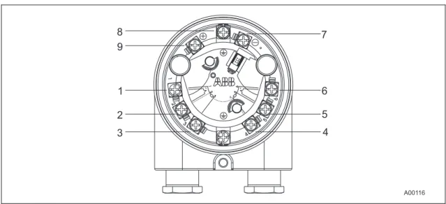
Fig. 6 Terminal for transmitter (without display)
1 … 6 Sensor connection
7 … 9 Signal/power supply connection 11 .. 42 VDC / 4 … 20 mA 11 .. 30 VDC / 4 … 20 mA (Ex)
7 Minus 8 Shield 9 Plus
1. Route the power supply cable through the cable gland into the housing of the transmitter. Then tighten the cable gland.
2. Strip the wires and attach wire end sleeves.
3. Release the clamping screws for the (+) and (-) terminals with the proper screwdriver. Make sure that the screws do not fall out.
4. Connect the (+) wire to the (+) terminal on the transmitter. 5. Connect the (-) wire to the (-) terminal on the transmitter.
Note
1 2
3 5
6
1
2
3
4 5
6
4
A00117 1
2
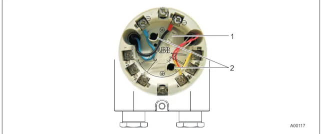
Fig. 7 Connection example
1 Socket (HMI interface) for LC display 2 Retaining socket for the LC display
5.3 Connection for measuring element
Note
The measuring element is connected via sensor connecting cable. The sensor connecting cable is not delivered with the transmitter. It must be ordered as a separate accessory. The model of the sensor connecting cable must correspond to the sensor model and configuration of the transmitter.
When connecting the transmitter and measuring inset (sensor) make sure for thermocouple sensors that the material of the sensor connecting cable corresponds to the thermocouple model.
1. Look for the connection type for the selected measuring element in the connection diagrams. 2. Release the clamping screws for terminals 1 to 6 using the proper screwdriver. Make sure
that the screws do not fall out.
3. Insert the wires for the measuring element and sensor cable connection under the open terminals and carefully tighten the clamping screws for the connections.
Note
The wires for the sensor connecting cable can also be soldered to the soldering tags for the terminals in the transmitter.
5.4 Terminal connection diagrams
RTD resistance sensors
Fig. 8
Potentiometer: 0 … 500 Ω or 0 … 5000 Ω
1 Potentiometer, 4-wire circuit 2 Potentiometer, 3-wire circuit 3 Potentiometer, 2-wire circuit
4 2 x RTD, 3-wire circuit (sensor backup/redundancy, average value or differential temperature measurement) 5 2 x RTD, 2-wire circuit (sensor backup/redundancy, average value or differential temperature measurement) 6 RTD, 4-wire circuit
7 RTD, 3-wire circuit 8 RTD, 2-wire circuit
Thermocouples/Voltages + -+ -+ -+ -11 … 30(Ex) 42 VD C/4…2 0m A
+
-1 1 2 3 4 5 6 1 2 3 4 5 6 4 3 1 2 5 12 11 10 2K A00084 5 6 + -2K 5 62 2 2
+
-9
1K 1K
2
1 1 1 1
6
Fig. 9
9 2 x voltage measurement (sensor backup/redundancy, average value or differential temperature measurement) 10 Voltage measurement
11 2 x thermocouple (sensor backup/redundancy, average value or differential temperature measurement) 12 Thermocouple
RTD/thermocouples configuration
Fig. 10
13 1 x RTD, 4-wire circuit and thermocouple 14 1 x RTD, 3-wire circuit and thermocouple 15 1 x RTD, 2-wire circuit and thermocouple
5.4.1 Standard application
Field Control room
Fig. 11
A Transmitter B Repeater power supply / SPS input with
supply
When connecting transmitters and repeater power supplies, observe the following specification: UMmin ≤ USmin + 0.02A x RLtg
Where
UMmin: Minimum operating voltage of transmitter (refer to technical data for transmitter) USmin : Minimum supply voltage of repeater power supply / SPS input
RLtg: Line resistance between transmitter and repeater power supply
For HART functionality, use repeater power supplies or SPS input cards with Hart mark. If this is not possible, the interconnection must have a resistance ≥ 250 Ω (< 1100 Ω).
The signal line can be connected with or without ground. When connecting the ground (minus side), make sure that only one side of the contact is connected to the equipotential bonding system.
5.4.1.1 Standard application with HART functionality
Field Control room
Fig. 12
A Transmitter B Repeater power supply / SPS input with
supply
Adding resistance R250 increases the minimum supply voltage: UMmin ≤ USmin + 0.02A x (RLtg + R250)
Where
UMmin: Minimum operating voltage of transmitter (refer to technical data for transmitter) USmin : Minimum supply voltage of repeater power supply / SPS input
RLtg: Line resistance between transmitter and repeater power supply R250: Resistance for HART functionality
5.4.1.2 Electrical interconnection in explosion risk area
Special interconnections are required for use in hazardous areas depending on the safety requirements.
Intrinsic safety
The feed separator / SPS inputs must have corresponding input protection circuits available in order to eliminate a hazard (spark formation). An interconnection inspection must be performed. For proof of the intrinsic safety, the electrical limit values are to be used as the basis for the prototype test certificates of the apparatuses (devices), including capacitance and inductivity values of the wires. The proof of the intrinsic safety is given if the following conditions are fulfilled with comparison of the limit values of the aparatus.
Transmitter
(intrinsically safe apparatus)
Feed separator / SPS input
(related apparatus)
Ui ≥ Uo
Ii ≥ Io
Pi ≥ Po
Li + Lc (cable) ≤ Lo
Ci + Cc (cable) ≤ Co
Field (Ex area) Control room (secure area)
Fig. 13
A Transmitter B Feed separator / SPS input with feed
Note
Observe the “Technical specifications” and “Explosion-protection technical data” chapters (see data sheet and/or operating instructions).
5.4.2 Installation in ignition protection areas
Transmitters can be installed in a wide variety of industrial sectors. Systems that requires ignition protection are divided into zones. As a result, different instruments are also required. For additional information, refer to the section “Explosion-protection relevant information” or the data sheet.
5.4.2.1 Zone 0
Transmitter design: II 1G EEx ia IIC T6
Zone 0 Explosion-protection zone 0 Safety area
B C
ia
A00120 ia
J
A
Fig. 14
A Sensor
B TTF300 transmitter
C Repeater power supply [EEx ia]
The input for the repeater power supply must be in EEx ia design.
When using the transmitter in zone 0, make sure you prevent electrostatic charging of the temperature transmitter (observe warnings on equipment).
The sensor must be used by the user in accordance with applicable ignition-protection standards.
5.4.3 Zone 1 (0)
Transmitter design: II 2 (1) G EEx [ia] ib IIC T6
Zone 0 or Zone 1 Explosion-protection zone 1 Safety area
B C
ib
A00121 ia
J
A
Fig. 15
A Sensor
B TTF300 transmitter
C Repeater power supply [EEx ib]
The input for the repeater power supply must be at a minimum in EEx ib design.
The sensor must be used by the user in accordance with applicable ignition-protection standards. It can be installed in zone 1 or zone 0. For zone 0, the circuit must be in "ia" design.
5.4.4 Zone 1 (20)
Transmitter design: II 2G (1D) EEx [iaD] ib IIC T6
Zone 0, Zone 1,
Zone 20 Explosion-protection zone 1 Safety area
ib
B C
ib
A00122 ia
J
A
Fig. 16
A Sensor
B TTF300 transmitter
C Repeater power supply [EEx ib]
The input for the repeater power supply must be at a minimum in EEx ib design.
The sensor must be used by the user in accordance with applicable ignition-protection standards. It can be installed in zone 0, zone 1 or zone 20. For zone 0 and zone 20, the circuit must be in "ia" design.
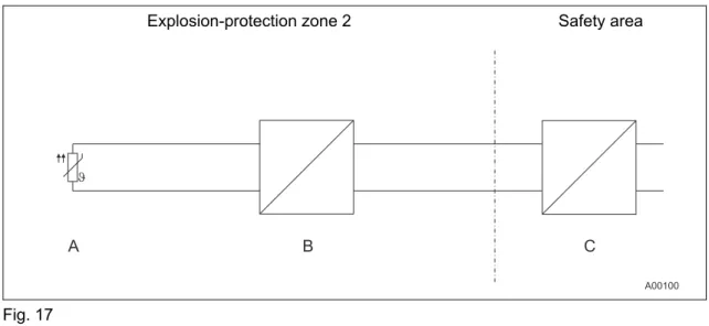
5.4.5 Zone 2
Transmitter design: II 3G EEx nA II T6
Explosion-protection zone 2 Safety area
Fig. 17
A Sensor
B TTF300 transmitter
C Repeater power supply
Ensure that in case of a disturbance the supply voltage cannot exceed 40% of the normal voltage.
5.4.6 Dust-explosion protection Zone 20:
Transmitter design: ATEX II 1D IP65 T135°C
Explosion-protection zone 20 Safety area
B C
A00119 J
A
D
Fig. 18
A Sensor
B TTF300 transmitter
C Repeater power supply D Fuse, 32 mA
The electric circuit of the transmitter must be limited by an upstream fuse per IEC 127 with a fuse current rating of 32 mA. This is not required if the power supply is in intrinsically safe "ia" design.
5.4.7 Dust-explosion protection Zone 0/20
Housing design: ATEX II 1D IP65 T135°C Transmitter design: ATEX II 1G EEx ia IIC T6
Explosion-protection zone 0
Explosion-protection zone 20 Safety area
B C
A00123 J
A
D ia
Fig. 19
A Sensor
B TTF300 transmitter
C Repeater power supply D Fuse, 32 mA
When using the sensor in zone 0, the transmitter must be in EEx ia (category 1G) design.
If the transmitter is designed with intrinsic safety, the power supply must provide an intrinsically safe circuit.
5.4.8 Hermetically sealed zone 1
Housing design: ATEX II 2G EEx d IIC T6 Transmitter design: No ignition protection
Explosion-protection zone 1 Safety area
B C
A00124 J
A
Fig. 20 A Sensor
B TTF300 transmitter in Ex d housing
5.4.9 Hermetically sealed zone 0
Housing design: ATEX II 2G EEx d IIC T6 Transmitter design: ATEX II 1G EEx ia IIC T6
Explosion-protection zone 0
Explosion-protection zone 1 Safety area
B C
A00125 J
A
ia ia
Fig. 21 A Sensor
B TTF300 transmitter in Ex d housing
C Repeater power supply
The input for the repeater power supply must be in EEx ia design.
The sensor must be used by the user in accordance with applicable ignition-protection standards. It can be installed in zone 1 or zone 0. For zone 0, the circuit must be in "ia" design.
6 Start-up
Note
The transmitter is immediately ready for operation after mounting and installation of the connections. The parameters are set at the factory (default or customer-specific).
The connected wires must be checked for firm seating. Only firmly seated wires ensure a full functionality.
K
7 Configuration
7.1 Configurations
There are four possible transmitter configurations: • via optional, plug-on LC display with control buttons. • via HART protocol and handheld terminal
• via HART protocol with FSK modem, PC and SmartVision configuration software. via DTM in FDT1.2 network applications
* if necessary Fig. 22
1 Handheld terminal 2 FDT/DTM technology
3 Ground connection (optional) 4 Power supply (process interface)
7.1.1 HART communication
Communication with the transmitter is supported by the HART protocol. The communication signal is modulated on both wires for the power supply line and decoded by the transmitter. The electrical connection is provided either by two test pins at the (+) and (–) terminals of the
7.1.2 Configuration via the LCD display with the control buttons
During operation, the name of the measuring location of the flowmeter primary and a trend display are shown on the LCD display.
Note
In contrast to the SmartVision software, the functionality of the transmitter with the LCD display and the control buttons is only partially changeable.
The configuration of the transmitter parameters is described in the “Configuration with the LCD display and the control buttons” paragraph in this operating instructions.
7.1.3 Configuration with the handheld terminal
The configuration with the handheld terminal normally takes place at the factory before the installation of the transmitter in an industrial plant.
1. Open the housing of the head-mounted measuring inset.
2. Carefully clamp both test tips of the separate operating control on the contacts in the slotting in front of the + and – connection terminals.
3. Be sure the test terminals are firmly seated.
4. The installation is to be realized according to the figure in the “Configuration types” paragraph.
Note
The connection of the test tips is performed without polarity. Thus, it does not make a difference which test tip is clamped to which + or – connection terminal.
The configuration of the transmitter via the HART protocol can also take place during the normal operation.
7.1.4 Configuration with SmartVision
SmartVision configuration software is required to fully modify the functionality of the transmitter, including characteristic curves.
For configuration during operation in explosion-protection areas, the FSK modem must comply with ignition-proof requirements (use an Ex modem).
To connect with SmartVision, a DTM (Device Type Manager) is required. For additional information, refer to DTM documentation.
7.2 Configuration via the LCD display and the control buttons
The configuration of the transmitter is done using the buttons below the LCD display on the front side of the housing. The buttons and the LCD display are in a protected location under the housing cover with inspection glass. The housing cover must be unscrewed before the transmitter is configured.
A00104 5
6 4
3 2 1
Fig. 23
1 Error message 2 Bar graph 3 Display value
4 HART tag 5 Unit
7.3 Menu navigation
Fig. 24
• The (1),(4), (2) und (3) buttons are available for the menu-controlled configuration. • The menu/submenu designation is displayed above in the LCD display.
• The number/line of the currently selected menu item is displayed in the upper right of the LCD display.
• A scroll bar is located on the right edge of the LCD display which shows the relative position of the currently selected menu item within the menu.
• Both of the and buttons can have various functions assigned to them. The meaning of these buttons is displayed below in the LCD display above the respective button. The following functions are possible.
Button functions Meaning
Exit Exit menu.
Back Back one submenu.
Cancel Exit without saving the selected parameter value. Next Select next digit for entering numerical values.
Button functions Meaning
Select Select submenu/parameter.
Edit Edit parameter.
OK Save selected parameter and display stored parameter
value.
• You can browse through the menu or select a number within a parameter value using both
or buttons. The button selects the desired menu item.
7.3.1 Calling up the menu
Fig. 25
1 Entering the menu
1. First, the transmitter voltage supply must be switched on. The “ABB connecting …“ display appears after a few seconds. The “Primary VAL“ value is subsequently displayed.
2. A symbol for calling up the menu is located in the LCD display above the button. By pressing the button, the configuration menu is called up. The “Config Device” main menu is displayed.
7.3.2 Selecting a menu item/parameter
• The desired submenu must be selected if the menu contains submenus.
• You can only then select a parameter when the corresponding submenu contains configurable parameters e.g. “Sensor type”.
7.3.3 Configuring a parameter value
1. If a parameter in a submenu is selected, the current configurable parameter value is displayed.
2. By pressing the “Edit“ button, either all configurable parameter values or a numerical value to be set are displayed. The currently configured parameter value is highlighted. Using the “HART tag“ example, the alphanumeric operation is also possible. The character position of the tag no. is determined with the button. The corresponding character can be selected from the character set with the and buttons.
7.3.4 Menu structure
The parameters are structured as a menu. The menu consists of a maximum of three levels. Menu items with the * have additional parameters that are called up in the next section.
Main menu Submenu 1 Submenu 2
Config Device Write protection Yes
No
Input sensor 1 Sensor type*
Connection type*
Output resistance Reference junction* Reference junction ext
Input sensor 2 Sensor type*
Connection type* Output resistance Reference junction* Reference junction ext
Input/output allocation Sensor 1 Sensor 2
Difference (S1-S2) Difference (S1-S2)
Mean Redundancy
Elec. measurement S1 Elec. measurement S2
Main menu Submenu 1 Submenu 2
Measuring range Unit*
Measurement start Measurement end Attenuation
Factory reset
Device info Device type
Serial number Software version
Hardware version HART tag
HART descriptor Operating hours
Display Display value Process data
Sensor 1 Sensor 2
Elec. measurement S1
Elec. measurement S2 Temp. electronics Output current
Main menu Submenu 1 Submenu 2
Language German
English Contrast
Process alarm Fault signaling Override
underdrive
Communication HART tag
Address (multi-drop)
HART burst mode Status*
Command #
Calibrate Measuring range Set measurement start
Set measurement end
Analog output Trim 4 mA
Trim 20 mA
Diagnostic Looptest
Device status
Electronics temperature max
min Sensor 1 process data max
min reset
Sensor 2 process data max min reset
7.4 Parameter description
The following further parameters for the device configuration are described below.
7.4.1 Config Device -> Input sensor 1 -> Sensor type 1 / 2
Sensor type 1 Sensor type 2
Pt100 (IEC751) Off
Pt1000 (IEC751) Pt100 (IEC751)
TC Type K (IEC584) Pt1000 (IEC751)
TC Type B (IEC584) TC Type K (IEC584)
TC Type C (ASTME988) TC Type B (IEC584)
TC Type D (ASTME988) TC Type C (ASTME988)
TC Type E (IEC584) TC Type D (ASTME988)
TC Type J (IEC584) TC Type E (IEC584)
TC Type N (IEC584) TC Type J (IEC584)
TC Type R (IEC584) TC Type N (IEC584)
TC Type S (IEC584) TC Type R (IEC584)
TC Type T (IEC584) TC Type S (IEC584)
TC Type L (DIN43710) TC Type T (IEC584)
TC Type U (DIN43710) TC Type L (DIN43710)
-125 … 125 mV TC Type U (DIN43710)
-125 … 1200 mV -125 … 125 mV
0 … 500 Ω -125 … 1200 mV
0 … 5000 Ω 0 … 500 Ω
Pt10 (IEC751) 0 … 5000 Ω
Pt50 (IEC751) Pt10 (IEC751)
Pt200 (IEC751) Pt50 (IEC751)
Pt500 (IEC751) Pt200 (IEC751)
Pt10 (JIS1604) Pt500 (IEC751)
Sensor type 1 Sensor type 2
Ni120 (DIN43760) Ni100 (DIN)
Ni1000 (DIN43760) Ni120 (DIN)
Cu10 a=4270 Ni1000 (DIN)
Cu100 a=4270 Cu10 a=4270
Fixpoint-Tabl.1 Cu100 a=4270
Fixpoint-Tabl.2 Fixpoint-Tabl.1 Fixpoint-Tabl.3 Fixpoint-Tabl.2 Fixpoint-Tabl.4 Fixpoint-Tabl.3 Fixpoint-Tabl.5 Fixpoint-Tabl.4 Combisensor Fixpoint-Tabl.5
Cal.van Dusen 1 Cal.van Dusen 1
Cal.van Dusen 2 Cal.van Dusen 2
Cal.van Dusen 3 Cal.van Dusen 3
Cal.van Dusen 4 Cal.van Dusen 4
Cal.van Dusen 5 Cal.van Dusen 5
7.4.2 Config Device -> Input sensor 1 -> connection type 1 / 2
Connection type 1 Connection type 2
2-wire 2-wire 3-wire 3-wire 4-wire -
7.4.3 Config Device -> Input sensor 1 -> Reference junction 1 / 2
Reference junction 1 Reference junction 2
internal internal without without
fixed externally Sensor 1 temperature
7.4.4 Config Device -> Measurement range -> Unit
Unit Description
°C Degrees Celsius
°F Degrees Farenheit
°R Degrees Rankine
K Kelvin User -
mV Millivolt
Ω Ohm
7.4.5 Communikation -> HART Burstmode -> Status
Status Command #
Off 1 Process data
On 2 Voltage + %
- 3 Voltage + Dyn. Vars
7.5 Factory settings
The transmitter is configured in the factory. The following table contains the values for the individual parameters.
Menu Designation Parameter Factory setting
Write protection - No
Sensor model Pt100(IEC751) Type of connection 3-wire
Line resistance 0.00 Ù Reference junction internal Input sensor 1
Reference point, ext 20.00 °C
Sensor model Off
Type of connection 3-wire Line resistance 0.00 Ù Reference junction internal Input sensor 2
Reference point, ext 20.00 °C
On/off assignment - Sensor 1
Unit °C Measurement start 0
Config device
Measuring range
Measurement end 100
Type of appliance - TTF300
Serial number - -
Software version - -
Hardware version - -
HART tag - -
HART descriptor - -
Device info
Operating hours - -
Display value - Process data
Bar graph - Yes
Bar graph data - Output %
Language - Deutsch
Display
Contrast - 50 %
Process alarm Fault signaling - Override
Menu Designation Parameter Factory setting
Set measurement start - °C Measuring range
Set measurement end - °C
Trim 4 mA 4.000 mA
Calibration
Analog output
Trim 20 mA 20.000 mA
Loop test - 0.00 mA
Diagnose
Device status - …
Electronics temperature - …
Sensor 1 process data - …
8 Error
messages
8.1 Error messages
The following list contains the error messages for the LC display.
Device Status
DIAG. NO.
Source of Error Error correction
Device F 1 Device defective. Replacing the device.
Device S 2
Above/below ambient temperature.
Check environment, possibly reposition measuring point.
Device F 3 EEPROM defective. Replacing the device.
Device M 4
Electronics overload. Reset to factory settings, notify service of error message.
Device F 5
Memory error. Reset to factory settings, notify service of error message.
Device I 7 HMI inserted. Status info, no error.
Device I 8 Device write-protected. Status info, no error.
Device I 9 EEPROM busy. Status info, no error.
Device F 12 Sensor input defective (communication). Replacing the device.
Device F 13
Sensor input defective
(error). Replacing the device.
Device F 14
Sensor input defective (ADC error).
Replacing the device.
Communication-related
Communication C 32 Diagnostic simulation mode No error, diagnostic info, measurement OK.
Sensor-related Channel
1
Sensor 1 F 34 Measuring error. Check sensor connection.
Sensor 1 F 35 Sensor short-circuit. Check sensor connection.
Sensor 1 F 36 Wire break. Check sensor connection.
Device Status
DIAG. NO.
Source of Error Error correction
Sensor 1 F 38 Below sensor range. Check measuring limits.
Sensor 1 I 41 Single point calibration active. Status info, no error. Sensor 1 I 42 Two point calibration active. Status info, no error.
Sensor-related Channel 2
Sensor 2 F 50 Measuring error. Check sensor connection.
Sensor 2 F 51 Sensor short-circuit. Check sensor connection.
Sensor 2 F 52 Wire break. Check sensor connection.
Sensor 2 F 53 Above sensor range. Check measuring limits. Sensor 2 F 54 Below sensor range. Check measuring limits.
Sensor 2 I 57 Status info. Status info, no error.
Sensor 2 I 58 Status info. Status info, no error.
Application-related
Application F 65
Configuration defective. Check configuration: A) Incorrect device. B) Measuring span is
too small. Incorrect configuration data.
Application M 66
No sensor detected at sensor 1 in redundancy configuration.
Check connection.
Application M 67
No sensor detected at sensor 2 in redundancy configuration.
Check connection.
Application C 71 Reconfiguration is running. Status info, no error.
Application F 72
Incorrect application. Check configuration, connections; reset to factory settings; notify service.
Device Status
DIAG. NO.
Source of Error Error correction
Application C 75 Analog output in simulation. Status info, no error.
Application S 76
Above range. Check parameters: A) Above sensor
range. Measuring span is too small.
Application S 77 Limit HIGH HIGH. Refer to Hart variable. Application S 78 Limit LOW LOW. Refer to Hart variable.
Application S 79 Limit HIGH. Refer to Hart variable.
Application S 80 Limit LOW. Refer to Hart variable.
Explanations per NE107
Designation Description
I OK or Information
C Check Function
S Off Specification
M Maintenance Required
9 Maintenance / Repair
9.1 General information
For transmitters that are used as intended under normal operation, no maintenance is required. No on-site repair or replacement of electronic parts is planned.
Note
Read the technical data on drift.
Warning! Risk of explosion!
Faulty transmitters may not be placed into operation by the user. Repairs must be performed in the production plant.
9.1.1 Cleaning
When cleaning the exterior of meters, make sure that the cleaning agent used does not corrode the housing surface and the seals.
9.2 Disposal WEEE directive 2002/96/EC
This device is not subject to the WEEE directive 2002/96/EC and relevant national laws (e.g., ElektroG in Germany). Dispose of the device at a specialized recycling facility. Do not dispose of the device in the municipal garbage.
10 Explosion-protection relevant information
10.1 TTF300-E1… (intrinsically safe)
Wechsel ein-auf zweispaltig
Approved for use in zone 0.
Designation:
• II 1G EEx ia IIC T6 (Zone 0) • II 2 (1) G EEx [ia] ib IIC T6 (zone 1 [0]) • II 2 G (1D) Ex [iaD] ib IIC T6 (zone 1 [20])
Note
The Ex or ignition-proof designation is provided on the name plate.
EC prototype test certificate: Refer to PTB 05 ATEX2017 X.
Temperature table
Permissible ambient temperature range Temperature
class Device category 1
use
Device category 2 use
T6 -50 … 44 °C -50 … 56 °C
T5 -50 … 56 °C -50 … 71 °C
T4 -50 … 84 °C -50 … 85 °C
Wechsel ein-auf zweispaltig
Safety-relevant data
Intrinsically safe EEx ia IIC explosion protection
Supply circuit Measurement current
circuit / passive transducer (RTD)
Measurement current circuit / active transducer (RTD)
Display interface
Max. voltage Ui = 30 V Uo = 6.5 V Uo = 1.2 V Uo = 6.2 V
Short-circuit current Ii = 130 mA Io = 25 mA Io = 50 mA Io = 65.2 mA
Max. power Pi = 0.8 W Po = 38 mW Po = 60 mW Po = 101 mW
Internal inductance Li = 490 µH Li = 0 mH Li = 0 mH Li = 0 mH
Internal capacitance Ci = 3.63 nF Ci = 49 nF Ci = 49 nF Ci = 0 nF
Maximum permissible
external inductance Lo= 5 mH Lo = 5 mH Lo= 5 mH
Maximum permissible
external capacitance Co= 1.55 µF Co= 1.05 µF Co= 1.4 µF
Wechsel ein-auf zweispaltig
10.2 TTF300-E2… (nonincendive)
Approved for use in zone 2/22.
Designation:
• II 3 G EEx n A II T6 • II 3 D IP 65 T 135 °C
Note
The Ex or ignition-proof designation is provided on the name plate.
ABB statement of conformity in accordance with ATEX directive.
Temperature table
Temperature class
Permissible ambient temperature range
T6 -50 °C … 56°C
T5 -50 C … 71°C
CSA and FM
Intrinsically safe (in preparation)
FM Class I, Div. 1 + 2, Groups A, B, C, D T6 Class II, Groups E, F, G; Class III Class I, Zone 0, AEx ia IIC T6 Control drawing: TTF300-L1
CSA Class I, Div. 1 + 2, Groups A, B, C, D Class II, Groups E, F, G; Class III Control drawing: TTF300-R1
Nonincendive (in preparation)
FM Class I, Div. 2, Groups A, B, C, D (Class II, Groups E, F, G; Class III Control drawing: TTF300-L2
CSA Class I, Div. 2, Groups A,B,C,D (Class II, Groups E, F, G; Class III Control drawing: TTF300-R2
Dust-explosion protection:
TTF300-D1... Dust-explosion protection
Dust / Zone 20:
Designation: "Ex mark" II 1 D IP 65 T 135°C EC prototype test certificate BVS 06 ATEX E 029
TTF300-D2... Dust-explosion protection + Intrinsic safety
Dust / Zone 20 + Gas / Zone 0:
Designation: "Ex mark" II 1 D IP 65 135°C "Ex mark" II 1G EEx ia IIC T6 EC prototype test certificate BVS 06 ATEX E 029 EC prototype test certificate PTB 05 ATEX 2017 X
Hermetically sealed
TTF300-E3….hermetically sealed
Zone 1:
Designation: "Ex mark" II 2G EEx d IIC T6 EC prototype test certificate PTB 99 ATEX 1144
TTF300-E4….hermetically sealed + intrinsic safety
Zone 1:
Designation: "Ex mark" II 2G EEx d IIC T6 "Ex mark" II 1G EEx ia IIC T6 EC prototype test certificate PTB 99 ATEX 1144 EC prototype test certificate PTB 05 ATEX 2017 X
Explosion-proof
TTF300-L3... FM explosion-proof
XP,NI, DIP Class I, II, III, Div. 1 + 2, Groups A-G, factory sealed Control drawing: TTF300-L3
TTF300-R4... CSA explosion-proof
XP,NI, DIP Class I, II, III, Div. 1 + 2, Groups A-G, factory sealed Control drawing: TTF300-R3
11 Approvals
Wechsel ein-auf zweispaltig
11.1 TTF300
CE mark
The TTF300 meets all requirements for the CE mark in accordance with IEC 61326 (2002).
Namur
The TTF300 complies with NAMUR NE 21 (02/2004).
Ignition protection
The TTF300 meets requirements for ATEX, FM and CSA. For additional information, refer to the section "Explosion-protection relevant information").
SIL: Functional safety (optional)
In preparation in accordance with IEC 61508.
Device with certificate of conformity for use in safety-relevant applications, including SIL 2 type.
11.2 LC display
CE mark:
The HMI type A LC display meets all requirements for the CE mark in accordance with IEC 61326 (2001).
Namur:
The HMI type A LC display complies with NAMUR NE 21 (02/2004).
CSA and FM
Intrinsic Safety (in preparation)
FM Class I, Div. 1, Groups A, B, C, D T6 Class I, Zone 0, AEx ia IIC T6 Control drawing:
CSA Class I, Div. 1, Groups A, B, C, D T6 Class I, Zone 0, AEx ia Group IIC T6 Control drawing:
Nonincendive (in preparation)
FM Class I, Div. 2, Groups A, B, C, D, T6 Control drawing:
CSA Class I, Div. 2, Groups A,B,C,D T6 Control drawing:
12 Technical data
Wechsel ein-auf zweispaltig
12.1 Input
12.1.1 Resistance
RTD resistance thermometer
Pt100 in accordance with DIN IEC 60751, JIS, MIL, Ni in accordance with DIN 43760, Cu (for additional information, see the section "Measurement accuracy")
Resistance measurement
0 … 500 Ω
0 … 5000 Ω
Sensor connections
2-, 3-, 4-wire circuit
Connecting cables
2-, 3-, 4-wire max. sensor line resistance (RW)for each wire 50 Ω in accordance with NE 89 (March 2003);
(3-wire balanced, 2-wire circuit compensation up to 100 Ω sensor total line resistance)
Measurement current
< 300 µA
Sensor short-circuit
< 5 Ω (for RTD)
Sensor wire break (temperature resistance measurement 2-, 3-, 4-wire)
Measuring range 0 ... 500 Ω > 0,6 ... 10 kΩ Measuring range 0 ... 5 kΩ > 5,3 ... 10 kΩ
Corrosion detection in accordance with NAMUR NE 89
3-wire resistance reading > 50 Ω 4-wire resistance reading > 50 Ω
12.1.2 Thermocouples/Voltages
Types
B, E, J, K, L, N, R, S, T, U, C, D (see "Measurement accuracy")
Voltages
-125 mV ... 125 mV -125 mV ... 1100 mV
Connecting cables
Max. sensor line resistance (RW) for each line 1.5 kΩ, total 3 kΩ
Sensor wire break monitoring in accordance with Namur NE 89
pulsed with 1 µA outside the measurement interval Thermocouple measurement 5.3 ... 10 kΩ with 45% hysteresis
Voltage measurement 5.3 ... 10 kΩ with 45% hysteresis
Input functionality
1 Sensor 2 Sensors: mean measurement
Differential measurement: Zero point where Ia = 4 mA Differential measurement: Zero point where Ia = 12 mA Sensor redundancy
Sensor fault signaling
RTD sensor: Short circuit and wire break Linear resistance measurement: Wire break
Thermocouples: Wire break
Linear voltage measurement: Wire break
12.2 Output Transmission characteristics temperature linear resistance linear voltage linear Output signal
Configurable 4 ... 20 mA (standard) Configurable 20 ... 4 mA
(NE43 dynamic range: 3.8 ... 20.5 mA)
Simulation mode
3.5 ... 23.6 mA
Induced current consumption
< 3.5 mA
Maximum output current
23.6 mA
Configurable error current signal
override 22 mA (20.0 … 23.6 mA) underdrive 3.6 mA (3.5 … 4.0 mA)
12.3 Power supply (polarity safe)
Wechsel ein-auf zweispaltig Supply voltage
(2-wire technique; power lines = signal lines)
Supply voltage
Non ignition-proof application with or without LC display1): US = 11 ... 42 V DC
Ignition-proof applications with or without LC display1): US = 11 ... 30 V DC
1) TTH300 with LC display, built into thermometer, see data sheets DS/TSP1X1 and DS/TSP3X1
Max. permissible residual ripple for supply voltage
Max. permissible ripple for supply voltage during communication in accordance with HART FSK "Physical Layer" specification, version 8.1 (08/1999) Section 8.1
Undervoltage detection
UTerminal-Mu < 10 V results in Ia = 3.6 mA
Max. load
Rload = (supply voltage: 11 V)/0.022 A
Max. load (Ω) depending on supply voltage (V DC)
Fig. 3: A TTH300
B TTH300 in EEx ia design
C HART communication resistance
Max. power consumption
P = Us x 0.022 mA
e.g., Us = 24 V
→
Pmax = 0.528 W12.4 General information
Galvanic isolation
(input/output) 3.5 kV AC (approx. 2.5 KV DC) 60 s
MTBF time 28 years at 60 °C ambient
temperature
Input filter 50 / 60 Hz
Switch-on delay < 10 s (Ia≤ 3.6 mA during starting
cycle)
Warm-up time 5 min.
Ramp-up time t90 150 … 600 ms
Update reading 1) 10/s with 1 sensor, 5/s with 2 sensors
Output filter Digital filter 1st order: 0 ... 100 s
1) depending on sensor type and sensor circuit
kj
12.5 Ambient conditions
Ambient temperature:
Standard: -40 … 85 °C / -40 … 185 °F Optional: -50 … 85 °C / -58 … 185 °F
For use with LC display HMI type A: -20 … 70 °C / -4 … 158 °F
For ignition-proof design, see prototype test certificate PTB 05 ATEX 2079 X.
Storage temperature: -40 … 85 °C / -40 … 185 °F
Climate class: Cx (-40 … 85 °C / -40 … 185 °F,
5 … 95% relative humidity) DIN EN 60654-1
Max. permissible
humidity: 100% relative humidity, condensation permitted in accordance with IEC 68-2-6
Vibration resistance: 10 … 2000 / 5 Hz acc. to IEC 68-2-6
Shock: gn = 30 in accordance with IEC 68-2-27
Earthquake resistance: Acc. to EN1473
Salt fog: Acc. to IEC 68-2-11
Type of protection: IP66 and IP67; NEMA 4X, ENCL 4X
12.6 Electromagnetic compatibility
Emitted interference in accordance with IEC 61326 (2002) and Namur NE21 (02/2004)
12.7 Interference immunity
Interference immune in accordance with IEC 61326 (2002) and Namur NE21 (02/2004)
Pt100: Measuring range 0 ... 100 °C, span 100 K
Type of test Testing accuracy Influence
Burst to signal/data lines 2 kV < 0.5% Static discharge
• Contact plate (indirect) • Supply terminals1) • Sensor terminals1)
8 kV 6 kV 4 kV no no no Radiated field
80 MHz ... 2 GHz 10 V/m < 0.5%
Coupling
150 kHz … 80 MHz 10 V < 0.5%
Surge
between the lines 0.5 kV no malfunction
Line to earth 1 kV no malfunction
13 LC display
Wechsel ein-auf zweispaltig
Dual function: LC display with TTF300 configuration options
13.1 Features of LC display
• Transmitter-controlled graphic (alphanumeric) LC display
• Character height, mode-dependent
• Sign, 4 digits, 2 decimal places • Bar graph display
• Rotatable in 30° increments
• Display options:
− Sensor 1 process data − Sensor 2 process data − Sensor 1 electrical (Ω / mV) − Sensor 2 electrical (Ω / mV) − Electronics/ambient temperature − Output/current
− Output %
• Display diagnostic information related to transmitter and sensor status
13.1.1 Technical data of LC display
Temperature range: -20 … 70 °C
(-50 … -20 °C or 70 … 85 °C no function)
Humidity: 0 … 100 %, condensation permitted
Dimensions: see the section Dimensioned drawings
Fig. 4
1 Exit/Cancel 2 Scroll back
3 Scroll forward 4 Select
13.2 Configuration function of LC display
• Configurable TTF300 transmitter parameters per display: All parameters
(sensor/type circuit, measuring range, error current signal, etc.) except: table-based sensor and freestyle characteristics, Callendar van Dusen coefficients, warning and alarm limits
• Hardware and software write protection for TTF300 configuration
13.3 LC display HMI ignition-proof type A (intrinsically safe)
Approved for use in zone 0.
Designation:
• II 1G EEx ia IIC T6
Note
The Ex or ignition-proof designation is provided on the name plate.
EC prototype test certificate: PTB 05 ATEX 2079 X
Temperature table
Permissible ambient temperature range Temperature
class Device category 1
use Device category 2 use
T6 -40 … 44 °C -40 … 56 °C
T5 -40 … 56 °C -40 … 71 °C
T4 -40 … 60 °C -40 … 85 °C
For the ambient temperature range from -50 °C to -20°C, additional mechanical protection is required.
Safety-relevant data
Intrinsically safe EEx ia IIC explosion protection
Supply circuit
Max. voltage Ui = 9 V
Short-circuit current Ii = 65.2 mA
Max. power Pi = 101 W
Internal inductance Li = 0 mH
Internal capacitance Ci = 0 nF
14 Appendix
14.1 Permits and certifications
Symbol Description
Ignition protection approvals
The Ex label indicates a device that complies with the directive 94/9/EC.
CE mark The CE mark indicates that the device complies with the following directives and their basic safety requirements:
• CE mark on the name plate of transmitter - Conforms with EMV directive 89/336/EWG - Conforms with low voltage directive 73/23/EWG • For ignition-protection applications:
Conforms with explosion-protection directive 94/9/EC (ATEX 95)
By placing the CE mark on its devices, ABB Automation Products GmbH declares its conformance with these directives.
Note
All declarations of conformity and certificates are available as a separate document in the download area of ABB Automation Products GmbH.
www.abb.com/temperature
14.2 Additional documents
• Getting started manual (CI//TTF300) • Data sheet (DS/TTF300)
14.3 Overview of device parameters and technical design
Measuring point: TAG no.:
Flowmeter model: Transmitter model:
Order no.: Device no.: Order no.:
Measured medium temp.: Power supply:
Lining: Electrodes: Exciter frequency:
Czero: Czero: System zero point:
Parameter Factory settings Alternate configurations
Sensor model 1 Pt100(IEC751) ...
Type of connection 3-wire ...
Line resistance 0.00 Ù ...
Reference junction internal ...
Reference point, ext 20.00 °C ...
Sensor model 2 TC type K ...
Type of connection 2-wire ...
Line resistance 0.00 Ù ...
Reference junction internal ...
Reference point, ext 20.00 °C ...
Channel config. Sensor 1 ...
Type of appliance - ...
Serial number 1 ...
Software version 0.2.1 ...
Hardware version 1.4 ...
HART tag - ...
HART descriptor - ...
Operating hours - ...
Display value Primary value ...
Bar graph No ...
Language English ...
Contrast 50 % ...
Measurement start 0.00 °C ...
Measurement end 100.00 °C ...
Unit °C ...
Damping 0.00 s ...
Failure signal Downscale ...
HART polling address Std + analog op ...
HART tag ´Space character´ ...
HART burst mode State: Off
Statement about the contamination of devices and components
The repair and/or maintenance of devices and components will only be performed when a completely filled out explanation is present.
Otherwise, the shipment can be rejected. This explanation may only be filled out and signed by authorized specialist personnel of the operator.
Customer details:
Company: Address:
Contact person: Telephone:
Fax: E-Mail:
Device details:
Type: Serial no.:
Reason for the return/description of the defect:
Was this device used for working with substances which pose a threat or health risk?
F Yes F No
If yes, which type of contamination (please place an X next to the applicable items)
biological F corrosive/irritating F combustible (highly/extremely combustible) F
toxic F explosive F other toxic substances F
radioactive F
Which substances have had contact with the device?
1. 2. 3.
We hereby certify that the devices/parts shipped were cleaned and are free from any dangerous or poisonous materials.
15 Index
Wechsel ein-auf zweispaltig
A
Additional documents ...54
Appendix ...54
C Conductor material ...15
Configurable error current signal ...51
Configuration...31, 32 Configuration via the LCD display and the control buttons...33
Configuration with SmartVision...32
Configuration with the handheld terminal ...32
Connecting cables ...51
Corrosion detection...51
D Design and function ...11
E Electrical installation safety information...9
Electrical interconnection...22
Entsorgen...47
Error messages...44
Explosion-protection relevant information ...48
F Factory settings...42
Freestyle characteristics ...51
G General information ...47
General Safety Information...6
I Induced current consumption ...51
L Labels and symbols ...7
LC display ...53
M Maintenance / Repair...47
Maximum output current ...51
Measurement current...51
N Name plate...8
Navigation ...34
O Operating safety information...9
Operator liability ...8
Output ...51
Output signal...51
P Permits and certifications...54
Personnel qualification...8
R Resistance ...51
Returning devices ...9
S Safety...6
Sensor connections ...51
Sensor short-circuit ...51
Sensor wire break ...51
Simulation mode ...51
Start-up ...31
V
Voltages ...51
W
Warranty provision ...7 WEEE-Richtlinie...47
Wechsel ein-auf zweispaltig
ABB provides expert and comprehensive consulting services in more than 100 countries worldwide.
www.abb.com/temperature
ABB is continually improving its products. As a result, technical information in this document is subject to change. Printed in the Fed. Rep. of Germany (05.2006)
© ABB 2006 3KXT221001R4201
OI/TTF300-E
N
ABB Limited
Salterbeck Trading Estate Workington, Cumbria CA14 5DS UK
Tel: +44 (0)1946 830 611 Fax: +44 (0)1946 832 661
ABB Inc.
125 E. County Line Road Warminster, PA 18974 USA
Tel: +1 215 674 6000 Fax: +1 215 674 7183
ABB Automation Products GmbH Borsigstr. 2
63755 Alzenau Germany
Tel: +49 551 905-534 Fax: +49 551 905-555 [email protected]