Veritas Storage Foundation™
and High Availability
Solutions 6.0.1 Disaster
Recovery Implementation
Guide - Linux
Veritas Storage Foundation™ and High Availability
Solutions Disaster Recovery Implementation Guide
The software described in this book is furnished under a license agreement and may be used only in accordance with the terms of the agreement.
Product version: 6.0.1 Document version: 6.0.1 Rev 2
Legal Notice
Copyright © 2014 Symantec Corporation. All rights reserved.
Symantec, the Symantec Logo, the Checkmark Logo, Veritas, Veritas Storage Foundation, CommandCentral, NetBackup, Enterprise Vault, and LiveUpdate are trademarks or registered trademarks of Symantec Corporation or its affiliates in the U.S. and other countries. Other names may be trademarks of their respective owners.
The product described in this document is distributed under licenses restricting its use, copying, distribution, and decompilation/reverse engineering. No part of this document may be reproduced in any form by any means without prior written authorization of Symantec Corporation and its licensors, if any.
THE DOCUMENTATION IS PROVIDED "AS IS" AND ALL EXPRESS OR IMPLIED CONDITIONS, REPRESENTATIONS AND WARRANTIES, INCLUDING ANY IMPLIED WARRANTY OF MERCHANTABILITY, FITNESS FOR A PARTICULAR PURPOSE OR NON-INFRINGEMENT, ARE DISCLAIMED, EXCEPT TO THE EXTENT THAT SUCH DISCLAIMERS ARE HELD TO BE LEGALLY INVALID. SYMANTEC CORPORATION SHALL NOT BE LIABLE FOR INCIDENTAL OR CONSEQUENTIAL DAMAGES IN CONNECTION WITH THE FURNISHING, PERFORMANCE, OR USE OF THIS DOCUMENTATION. THE INFORMATION CONTAINED IN THIS DOCUMENTATION IS SUBJECT TO CHANGE WITHOUT NOTICE.
The Licensed Software and Documentation are deemed to be commercial computer software as defined in FAR 12.212 and subject to restricted rights as defined in FAR Section 52.227-19 "Commercial Computer Software - Restricted Rights" and DFARS 227.7202, "Rights in Commercial Computer Software or Commercial Computer Software Documentation", as applicable, and any successor regulations. Any use, modification, reproduction release, performance, display or disclosure of the Licensed Software and Documentation by the U.S. Government shall be solely in accordance with the terms of this Agreement.
Symantec Corporation 350 Ellis Street
Mountain View, CA 94043 http://www.symantec.com
Technical Support
Symantec Technical Support maintains support centers globally. Technical Support’s primary role is to respond to specific queries about product features and functionality. The Technical Support group also creates content for our online Knowledge Base. The Technical Support group works collaboratively with the other functional areas within Symantec to answer your questions in a timely fashion. For example, the Technical Support group works with Product Engineering and Symantec Security Response to provide alerting services and virus definition updates.
Symantec’s support offerings include the following:
■ A range of support options that give you the flexibility to select the right amount of service for any size organization
■ Telephone and/or Web-based support that provides rapid response and up-to-the-minute information
■ Upgrade assurance that delivers software upgrades
■ Global support purchased on a regional business hours or 24 hours a day, 7 days a week basis
■ Premium service offerings that include Account Management Services For information about Symantec’s support offerings, you can visit our website at the following URL:
www.symantec.com/business/support/index.jsp
All support services will be delivered in accordance with your support agreement and the then-current enterprise technical support policy.
Contacting Technical Support
Customers with a current support agreement may access Technical Support information at the following URL:
www.symantec.com/business/support/contact_techsupp_static.jsp
Before contacting Technical Support, make sure you have satisfied the system requirements that are listed in your product documentation. Also, you should be at the computer on which the problem occurred, in case it is necessary to replicate the problem.
When you contact Technical Support, please have the following information available:
■ Product release level ■ Hardware information
■ Available memory, disk space, and NIC information ■ Operating system
■ Version and patch level ■ Network topology
■ Router, gateway, and IP address information ■ Problem description:
■ Error messages and log files
■ Troubleshooting that was performed before contacting Symantec ■ Recent software configuration changes and network changes
Licensing and registration
If your Symantec product requires registration or a license key, access our technical support Web page at the following URL:
www.symantec.com/business/support/
Customer service
Customer service information is available at the following URL: www.symantec.com/business/support/
Customer Service is available to assist with non-technical questions, such as the following types of issues:
■ Questions regarding product licensing or serialization
■ Product registration updates, such as address or name changes
■ General product information (features, language availability, local dealers) ■ Latest information about product updates and upgrades
■ Information about upgrade assurance and support contracts ■ Information about the Symantec Buying Programs
■ Advice about Symantec's technical support options ■ Nontechnical presales questions
Support agreement resources
If you want to contact Symantec regarding an existing support agreement, please contact the support agreement administration team for your region as follows:
[email protected] Asia-Pacific and Japan
[email protected] Europe, Middle-East, and Africa
[email protected] North America and Latin America
Documentation
Product guides are available on the media in PDF format. Make sure that you are using the current version of the documentation. The document version appears on page 2 of each guide. The latest product documentation is available on the Symantec website.
https://sort.symantec.com/documents
Your feedback on product documentation is important to us. Send suggestions for improvements and reports on errors or omissions. Include the title and document version (located on the second page), and chapter and section titles of the text on which you are reporting. Send feedback to:
For information regarding the latest HOWTO articles, documentation updates, or to ask a question regarding product documentation, visit the Storage and Clustering Documentation forum on Symantec Connect.
https://www-secure.symantec.com/connect/storage-management/ forums/storage-and-clustering-documentation
About Symantec Connect
Symantec Connect is the peer-to-peer technical community site for Symantec’s enterprise customers. Participants can connect and share information with other product users, including creating forum posts, articles, videos, downloads, blogs and suggesting ideas, as well as interact with Symantec product teams and Technical Support. Content is rated by the community, and members receive reward points for their contributions.
Technical Support
... 4Section 1
Introducing Veritas Storage Foundation
and High Availability Solutions for
disaster recovery
... 12Chapter 1
About supported disaster recovery scenarios
... 13About disaster recovery scenarios ... 13
About campus cluster configuration ... 16
VCS campus cluster requirements ... 16
How VCS campus clusters work ... 17
Typical VCS campus cluster setup ... 20
About replicated data clusters ... 22
How VCS replicated data clusters work ... 23
About global clusters ... 24
How VCS global clusters work ... 24
User privileges in global clusters ... 25
VCS global clusters: The building blocks ... 26
Disaster recovery feature support across Storage Foundation and High Availability Solutions 6.0.1 products ... 32
Replication agent support in virtual environments ... 35
Chapter 2
Planning for disaster recovery
... 37Planning for cluster configurations ... 37
Planning a campus cluster setup ... 37
Planning a replicated data cluster setup ... 38
Planning a global cluster setup ... 39
Planning for data replication ... 39
Data replication options ... 39
Data replication considerations ... 40
Contents
Section 2
Implementing campus clusters
... 41Chapter 3
Setting up campus clusters for VCS and SFHA
... 42About setting up a campus cluster configuration ... 42
Preparing to set up a campus cluster configuration ... 42
Configuring I/O fencing to prevent data corruption ... 43
Configuring VxVM disk groups for campus cluster configuration ... 43
Configuring VCS service group for campus clusters ... 45
Fire drill in campus clusters ... 46
About the DiskGroupSnap agent ... 46
About running a fire drill in a campus cluster ... 46
Configuring the fire drill service group ... 47
Running a successful fire drill in a campus cluster ... 47
Chapter 4
Setting up campus clusters for SFCFS, SFRAC
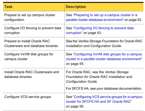
... 49About setting up a campus cluster for disaster recovery for SFCFS HA or SF Oracle RAC ... 49
Preparing to set up a campus cluster in a parallel cluster database environment ... 52
Configuring I/O fencing to prevent data corruption ... 53
Configuring VxVM disk groups for a campus cluster in a parallel cluster database environment ... 55
Configuring VCS service groups for a campus cluster for SFCFS HA and SF Oracle RAC ... 59
Tuning guidelines for parallel campus clusters ... 60
Best practices for a parallel campus cluster ... 60
Section 3
Implementing replicated data clusters
... 62Chapter 5
Configuring a replicated data cluster using
VVR
... 63About setting up a replicated data cluster configuration ... 63
About typical replicated data cluster configuration ... 63
About setting up replication ... 64
Configuring the service groups ... 65
Configuring the service group dependencies ... 66
About migrating a service group ... 66
Fire drill in replicated data clusters ... 67
8 Contents
Chapter 6
Configuring a replicated data cluster using
third-party replication
... 68About setting up a replicated data cluster configuration using third-party replication ... 68
About typical replicated data cluster configuration using third-party replication ... 69
About setting up third-party replication ... 69
Configuring the service groups for third-party replication ... 70
Fire drill in replicated data clusters using third-party replication ... 70
Section 4
Implementing global clusters
... 71Chapter 7
Configuring global clusters for VCS and SFHA
... 72Installing and Configuring Veritas Cluster Server ... 72
Setting up VVR replication ... 72
About configuring VVR replication ... 73
Best practices for setting up replication ... 73
Creating a Replicated Data Set ... 75
Synchronizing the Secondary and starting replication ... 91
Starting replication when the data volumes are zero initialized ... 97
Setting up third-party replication ... 98
Fire drill in global clusters ... 99
Chapter 8
Configuring a global cluster with Storage
Foundation Cluster File System, Storage
Foundation for Oracle RAC, or Storage
Foundation for Sybase CE
... 100About global clusters ... 101
About replication for parallel global clusters using Storage Foundation and High Availability (SFHA) Solutions ... 101
About setting up a global cluster environment for parallel clusters ... 102
Configuring the primary site ... 103
Configuring the secondary site ... 107
Configuring the Sybase ASE CE cluster on the secondary site ... 112
Setting up replication between parallel global cluster sites ... 113
Testing a parallel global cluster configuration ... 119
9 Contents
Chapter 9
Configuring global clusters with VVR and Storage
Foundation Cluster File System, Storage
Foundation for Oracle RAC, or Storage
Foundation for Sybase CE
... 121About configuring a parallel global cluster using Veritas Volume Replicator (VVR) for replication ... 122
Setting up replication on the primary site using VVR ... 124
Creating the data and SRL volumes on the primary site ... 124
Setting up the Replicated Volume Group on the primary site ... 126
Setting up replication on the secondary site using VVR ... 127
Creating the data and SRL volumes on the secondary site ... 128
Editing the /etc/vx/vras/.rdg files ... 129
Setting up IP addresses for RLINKs on each cluster ... 129
Setting up the disk group on secondary site for replication ... 130
Starting replication of the primary site database volume to the secondary site using VVR ... 132
Configuring Veritas Cluster Server to replicate the database volume using VVR ... 134
Modifying the Veritas Cluster Server (VCS) configuration on the primary site ... 139
Modifying the VCS configuration on the secondary site ... 144
Configuring the Sybase ASE CE cluster on the secondary site ... 149
Replication use cases for global parallel clusters ... 150
Section 5
Reference
... 158Appendix A
Sample configuration files
... 159Sample Storage Foundation for Oracle RAC configuration files ... 159
sfrac02_main.cf file ... 159
sfrac07_main.cf and sfrac08_main.cf files ... 160
sfrac09_main.cf and sfrac10_main.cf files ... 162
sfrac11_main.cf file ... 165
sfrac12_main.cf and sfrac13_main.cf files ... 166
Sample fire drill service group configuration ... 169
About sample main.cf files for Veritas Storage Foundation (SF) for Oracle RAC ... 171
Sample main.cf for Oracle 10g for CVM/VVR primary site ... 172
Sample main.cf for Oracle 10g for CVM/VVR secondary site ... 177
About sample main.cf files for Veritas Storage Foundation (SF) for Sybase ASE CE ... 181
10 Contents
Sample main.cf for a basic Sybase ASE CE cluster configuration under VCS control with shared mount point on CFS for
Sybase binary installation ... 182 Sample main.cf for a basic Sybase ASE CE cluster configuration
with local mount point on VxFS for Sybase binary
installation ... 186 Sample main.cf for a primary CVM VVR site ... 191 Sample main.cf for a secondary CVM VVR site ... 197
11 Contents
Introducing Veritas Storage
Foundation and High
Availability Solutions for
disaster recovery
■ Chapter 1. About supported disaster recovery scenarios ■ Chapter 2. Planning for disaster recovery
1
About supported disaster
recovery scenarios
This chapter includes the following topics: ■ About disaster recovery scenarios ■ About campus cluster configuration ■ About replicated data clusters ■ About global clusters
■ Disaster recovery feature support across Storage Foundation and High Availability Solutions 6.0.1 products
■ Replication agent support in virtual environments
About disaster recovery scenarios
Symantec Storage Foundation offers cost–effective, short-distance disaster recovery with active configurations and long distance replication solutions to effectively manage disaster recovery requirements.
This guide allows you to configure campus clusters, global clusters, and replicated clusters for disaster recovery failover using the following Storage Foundation and High Availability Solutions products:
■ Storage Foundation Cluster File System High Availability (SFCFSHA) ■ Storage Foundation™ for Oracle® RAC (SF Oracle RAC)
■ Storage Foundation™ for Sybase® Adaptive Server Enterprise Cluster Edition (SF Sybase CE)
■ Veritas Cluster Server (VCS)
1
■ Veritas Volume Replicator (VVR)
Note:Disaster recovery scenarios for SF Sybase CE have only been tested and are only supported using Veritas Cluster Volume Manager and Veritas Volume Replicator.
See theVeritas Storage Foundation Cluster File System Administrator's Guidefor more information on configuring SFCFSHA.
See theVeritas Storage Foundation for Oracle RAC Administrator's Guidefor more information on configuring SF Oracle RAC.
See theVeritas Storage Foundation for SF Sybase ASE CE Administrator's Guide
for more information on configuring SF Sybase CE.
See theVeritas Cluster Server Administrator's Guidefor more information on configuring VCS.
See theVeritas Storage Foundation and High Availability Solutions Replication Administrator's Guidefor more information on configuring VVR.
Table 1-1lists key use cases for campus cluster, global cluster, and replicated data cluster disaster recovery configurations.
Table 1-1 Key use cases for disaster recovery configurations
Recommended disaster recovery configuration
Use case description
Veritas Cluster Server HA/DR with Global Cluster Option (GCO)
See“ How VCS global clusters work” on page 24.
SFRAC with Global cluster option (GCO) Disaster Recovery of business-critical
applications from the production site to a geographically distributed Disaster Recovery (DR) site.
■ Distance between the two sites exceeds 80 KM or 50 miles
■ Application data is made available at the DR site through replication
■ Application is expected to be active at only one site at any point of time
(Active/Passive)
14 About supported disaster recovery scenarios
Table 1-1 Key use cases for disaster recovery configurations (continued)
Recommended disaster recovery configuration
Use case description
Veritas Cluster Server HA/DR with Replicated Data Cluster (RDC)
See“ How VCS replicated data clusters work” on page 23.
Disaster Recovery of business-critical applications from the production site to a geographically distributed Disaster Recovery (DR) site.
■ Distance between the two sites is less than 80 KM or 50 miles
■ Application data is made available at the DR site through replication
■ Application is expected to be active at only one site at any point of time
(Active/Passive)
Veritas Cluster Server HA/DR with Campus Cluster
See“ How VCS campus clusters work” on page 17.
Veritas Storage Foundation for remote mirroring
Disaster Recovery of business-critical applications from the production site to a geographically distributed Disaster Recovery (DR) site.
■ Distance between the two sites is less than 80 KM or 50 miles
■ Application data is made available at the DR site through remote mirroring ■ Application is expected to be active at only
one site at any point of time (Active/Passive)
■ Automatic application failover within a site, automated failover across sites
Veritas Cluster Server with Campus Cluster See“ How VCS campus clusters work” on page 17.
Veritas Storage Foundation Cluster File System for remote mirroring and parallel cross-site access
SFRAC with Campus Cluster for remote mirroring and parallel cross-site access High Availability of business-critical
applications across two geographically distributed sites.
■ Distance between the two sites is less than 80 KM or 50 miles
■ Application data is made available at the DR site through remote mirroring ■ Application is expected to be
simultaneously active at both the sites (Active/Active)
15 About supported disaster recovery scenarios
About campus cluster configuration
The campus cluster configuration provides local high availability and disaster recovery functionality in a single VCS cluster. This configuration uses data mirroring to duplicate data at different sites. There is no host or array replication involved. VCS supports campus clusters that employ disk groups mirrored with Veritas Volume Manager.
VCS campus cluster requirements
Review the following requirements for VCS campus clusters: ■ You must install VCS.
You must enable the HA/DR license if you want to manually control a service group failover across sites or system zones.
■ You must have a single VCS cluster with at least one node in each of the two sites, where the sites are separated by a physical distance of no more than 80 kilometers.
■ You must have redundant network connections between nodes. All paths to storage must also be redundant.
Symantec recommends the following in a campus cluster setup:
■ A common cross-site physical infrastructure for storage and LLT private networks.
■ Technologies such as Dense Wavelength Division Multiplexing (DWDM) for network and I/O traffic across sites. Use redundant links to minimize the impact of network failure.
■ Symantec recommends that you configure I/O fencing to prevent data corruption in the event of link failures.
■ You must install Veritas Volume Manager with the FMR license and the Site Awareness license.
■ You must configure storage to meet site-based allocation and site-consistency requirements for VxVM.
■ All the nodes in the site must be tagged with the appropriate VxVM site names.
■ All the disks must be tagged with the appropriate VxVM site names. ■ The VxVM site names of both the sites in the campus cluster must be added
to the disk groups.
16 About supported disaster recovery scenarios
■ The allsites attribute for each volume in the disk group must be set to on. (By default, the value is set to on.)
■ The siteconsistent attribute for the disk groups must be set to on.
■ Oracle requires that all of the nodes use IP addresses from the same subnet. ■ Each host at a site must be connected to a storage switch. The switch must
have access to storage arrays at all the sites..
■ Symantec recommends a common cross-site physical infrastructure for storage and LLT private networks
■ SF Oracle RAC campus clusters require mirrored volumes with storage allocated from both sites.
How VCS campus clusters work
This topic describes how VCS works with VxVM to provide high availability in a campus cluster environment.
In a campus cluster setup, VxVM automatically mirrors volumes across sites. To enhance read performance, VxVM reads from the plexes at the local site where the application is running. VxVM writes to plexes at both the sites.
In the event of a storage failure at a site, VxVM detaches all the disks at the failed site from the disk group to maintain data consistency. When the failed storage comes back online, VxVM automatically reattaches the site to the disk group and recovers the plexes.
See theVeritas Storage Foundation Cluster File System High Availability Administrator's Guidefor more information.
When service group or system faults occur, VCS fails over the service groups or the nodes based on the values you set for the service group attributes SystemZones and AutoFailOver.
For campus cluster setup, you must define the SystemZones attribute in such a way that the nodes at each site are grouped together.
Depending on the value of the AutoFailOver attribute, VCS failover behavior is as follows:
VCS does not fail over the service group or the node. 0
VCS fails over the service group to another suitable node. VCS chooses to fail over the service group within the same site before choosing a node in the other site.
By default, the AutoFailOver attribute value is set to 1. 1
17 About supported disaster recovery scenarios
VCS fails over the service group if another suitable node exists in the same site. Otherwise, VCS waits for administrator intervention to initiate the service group failover to a suitable node in the other site. This configuration requires the HA/DR license enabled.
Symantec recommends that you set the value of AutoFailOver attribute to 2.
2
Sample definition for these service group attributes in the VCS main.cf is as follows:
group oragroup1 (
SystemList = { node1=0, node2=1, node3=2, node4=3 } SystemZones = { node1=0, node2=0, node3=1, node4=1 } AutoFailOver = 2
... )
Table 1-2lists the possible failure scenarios and how VCS campus cluster recovers from these failures.
Table 1-2 Failure scenarios in campus cluster
Description and recovery Failure
■ A node in a site fails.
If the value of the AutoFailOver attribute is set to 1, VCS fails over the Oracle service group to another system within the same site that is defined in the SystemZones attribute.
■ All nodes in a site fail.
If the value of the AutoFailOver attribute is set to 1, VCS fails over the Oracle service group to a system in the other site that is defined in the SystemZones attribute.
If the value of the AutoFailOver attribute is set to 2, VCS requires administrator intervention to initiate the Oracle service group failover to a system in the other site.
If the value of the AutoFailOver attribute is set to 0, VCS requires administrator intervention to initiate a fail over in both the cases of node failure.
Node failure
The behavior is similar to the node failure. Application failure
18 About supported disaster recovery scenarios
Table 1-2 Failure scenarios in campus cluster (continued)
Description and recovery Failure
VCS does not fail over the service group when such a storage failure occurs.
VxVM detaches the site from the disk group if any volume in that disk group does not have at least one valid plex at the site where the disks failed.
VxVM does not detach the site from the disk group in the following cases:
■ None of the plexes are configured on the failed disks.
■ Some of the plexes are configured on the failed disks, and at least one plex for a volume survives at each site.
If only some of the disks that failed come online and if the vxrelocd daemon is running, VxVM relocates the remaining failed disks to any available disks. Then, VxVM automatically reattaches the site to the disk group and resynchronizes the plexes to recover the volumes. If all the disks that failed come online, VxVM automatically reattaches the site to the disk group and resynchronizes the plexes to recover the volumes.
Storage failure -one or more disks at a site fails
VCS acts based on the DiskGroup agent's PanicSystemOnDGLoss attribute value.
See theVeritas Cluster Server Bundled Agents Reference Guidefor more information.
Storage failure - all disks at both sites fail
All nodes and storage at a site fail.
Depending on the value of the AutoFailOver attribute, VCS fails over the Oracle service group as follows:
■ If the value is set to 1, VCS fails over the Oracle service group to a system in the other site that is defined in the SystemZones attribute. ■ If the value is set to 2, VCS requires administrator intervention to
initiate the Oracle service group failover to a system in the other site.
Because the storage at the failed site is inaccessible, VCS imports the disk group in the application service group with all devices at the failed site marked as NODEVICE.
When the storage at the failed site comes online, VxVM automatically reattaches the site to the disk group and resynchronizes the plexes to recover the volumes.
Site failure
19 About supported disaster recovery scenarios
Table 1-2 Failure scenarios in campus cluster (continued)
Description and recovery Failure
Nodes at each site lose connectivity to the nodes at the other site The failure of private interconnects between the nodes can result in split brain scenario and cause data corruption.
Review the details on other possible causes of split brain and how I/O fencing protects shared data from corruption.
Symantec recommends that you configure I/O fencing to prevent data corruption in campus clusters.
Network failure (LLT interconnect failure)
Nodes at each site lose connectivity to the storage and the nodes at the other site
Symantec recommends that you configure I/O fencing to prevent split brain and serial split brain conditions.
■ If I/O fencing is configured:
The site that loses the race commits suicide.
When you restore the network connectivity, VxVM detects the storage at the failed site, reattaches the site to the disk group, and resynchronizes the plexes to recover the volumes.
■ If I/O fencing is not configured:
If the application service group was online at site A during such failure, the application service group remains online at the same site. Because the storage is inaccessible, VxVM detaches the disks at the failed site from the disk group. At site B where the application service group is offline, VCS brings the application service group online and imports the disk group with all devices at site A marked as NODEVICE. So, the application service group is online at both the sites and each site uses the local storage. This causes inconsistent data copies and leads to a site-wide split brain. When you restore the network connectivity between sites, a serial split brain may exist.
See theVeritas Storage Foundation Administrator's Guidefor details to recover from a serial split brain condition.
Network failure (LLT and storage interconnect failure)
Typical VCS campus cluster setup
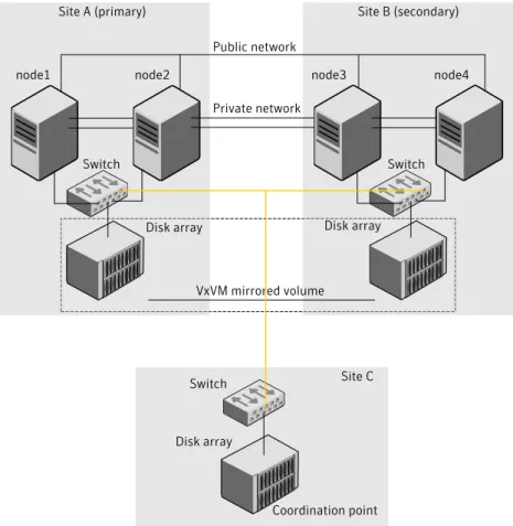
Figure 1-1depicts a typical VCS campus cluster setup.
20 About supported disaster recovery scenarios
Figure 1-1 Typical VCS campus cluster setup
Site A (primary) Site B (secondary)
node1 node2 node3 node4 Public network
Private network
Switch Switch
Disk array Disk array
Site C VxVM mirrored volume
Disk array Campus cluster
Switch
Coordination point
VCS campus cluster typically has the following characteristics: ■ Single VCS cluster spans multiple sites.
In the sample figure, VCS is configured on four nodes: node 1 and node 2 are located at site A and node 3 and node 4 at site B.
■ I/O fencing is configured with one coordinator disk from each site of the campus cluster and another coordinator disk from a third site.
Figure 1-1illustrates a typical setup with disk-based I/O fencing. You can also configure server-based I/O fencing.
Mix mode fencing with two coordinator disks from each site and a CP server on third site is also supported.
21 About supported disaster recovery scenarios
■ The shared data is located on mirrored volumes on a disk group configured using Veritas Volume Manager.
■ The volumes that are required for the application have mirrors on both the sites. ■ All nodes in the cluster are tagged with the VxVM site name. All disks that belong
to a site are tagged with the corresponding VxVM site name.
■ The disk group is configured in VCS as a resource of type DiskGroup and is mounted using the Mount resource type.
About replicated data clusters
In a replicated data cluster no shared disks exist. Instead, a data replication product synchronizes copies of data between nodes or sites. Replication can take place at the application, host, and storage levels. Application-level replication products, such as Oracle DataGuard, maintain consistent copies of data between systems at the SQL or database levels. Host-based replication products, such as Veritas Volume Replicator, maintain consistent storage at the logical volume level. Storage-based or array-based replication maintains consistent copies of data at the disk or RAID LUN level.
Figure 1-2shows a hybrid shared storage and replicated data cluster, in which different failover priorities are assigned to nodes according to particular service groups.
Figure 1-2 Shared storage replicated data cluster
Replication
Service Group
You can also configure replicated data clusters without the ability to fail over locally, but this configuration is not recommended.
See“ How VCS replicated data clusters work”on page 23.
22 About supported disaster recovery scenarios
How VCS replicated data clusters work
To understand how a replicated data cluster configuration works, let us take the example of an application configured in a VCS replicated data cluster. The configuration has two system zones:
■ Primary zone (zone 0) comprising nodes located at the primary site and attached to the primary storage
■ Secondary zone (zone 1) comprising nodes located at the secondary site and attached to the secondary storage
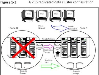
The application is installed and configured on all nodes in the cluster. Application data is located on shared disks within each RDC zone and is replicated across RDC zones to ensure data concurrency. The application service group is online on a system in the current primary zone and is configured to fail over in the cluster. Figure 1-3depicts an application configured on a VCS replicated data cluster.
Figure 1-3 A VCS replicated data cluster configuration
Public Network
Separate Storage Separate
Storage
Client Client Client Client
Replicated Data
Clients Redirected
Application Failover
Zone 0 Zone 1
Private Network
Service Group
Service Group
In the event of a system or application failure, VCS attempts to fail over the application service group to another system within the same RDC zone. However, in the event that VCS fails to find a failover target node within the primary RDC zone, VCS switches the service group to a node in the current secondary RDC zone (zone 1). VCS also redirects clients once the application is online on the new location.
23 About supported disaster recovery scenarios
About global clusters
A global cluster links clusters at separate locations and enables wide-area failover and disaster recovery.
Local clustering provides local failover for each site or building. Campus and replicated cluster configurations offer protection against disasters that affect limited geographic regions. Large scale disasters such as major floods, hurricanes, and earthquakes can cause outages for an entire city or region. In such situations, you can ensure data availability by migrating applications to sites located considerable distances apart.
Figure 1-4shows a global cluster configuration.
Figure 1-4 Global cluster
Public Network
Separate Storage Separate
Storage
Client Client Client Client
Replicated Data
Clients Redirected
Application Failover Oracle Group
Cluster A Cluster B
Oracle Group
In a global cluster, if an application or a system fails, the application is migrated to another system within the same cluster. If the entire cluster fails, the application is migrated to a system in another cluster. Clustering on a global level also requires the replication of shared data to the remote site.
See“ How VCS global clusters work”on page 24.
How VCS global clusters work
Local clustering provides local failover for each site or building. But, these configurations do not provide protection against large-scale disasters such as major floods, hurricanes, and earthquakes that cause outages for an entire city or region. The entire cluster could be affected by an outage.
24 About supported disaster recovery scenarios
In such situations, VCS global clusters ensure data availability by migrating applications to remote clusters located considerable distances apart.
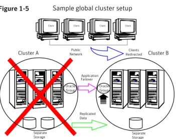
Let us take the example of an Oracle database configured in a VCS global cluster. Oracle is installed and configured in both clusters. Oracle data is located on shared disks within each cluster and is replicated across clusters to ensure data
concurrency. The Oracle service group is online on a system in cluster A and is configured to fail over globally, on clusters A and B.
Figure 1-5shows a sample global cluster setup.
Figure 1-5 Sample global cluster setup
Public Network
Separate Storage
Client Client Client Client
Replicated Data
Clients Redirected
Application Failover Oracle Group
Cluster A Cluster B
Oracle Group
Separate Storage
VCS continuously monitors and communicates events between clusters. Inter-cluster communication ensures that the global cluster is aware of the state of the service groups that are configured in the global cluster at all times.
In the event of a system or application failure, VCS fails over the Oracle service group to another system in the same cluster. If the entire cluster fails, VCS fails over the service group to the remote cluster, which is part of the global cluster. VCS also redirects clients once the application is online on the new location.
User privileges in global clusters
VCS permits a cross-cluster online or offline operation only if the user initiating the operation has one of the following privileges:
■ Group administrator or group operator privileges for the group on the remote cluster
■ Cluster administrator or cluster operator privileges on the remote cluster
25 About supported disaster recovery scenarios
VCS permits a cross-cluster switch operation only if the user initiating the operation has the following privileges:
■ Group administrator or group operator privileges for the group on both clusters ■ Cluster administrator or cluster operator privileges on both clusters
VCS global clusters: The building blocks
VCS extends clustering concepts to wide-area high availability and disaster recovery with the following:
■ Remote cluster objects
See“ Visualization of remote cluster objects”on page 26. ■ Global service groups
See“About global service groups”on page 27. ■ Global cluster management
See“About global cluster management”on page 27. ■ Serialization
See“About serialization–The Authority attribute”on page 28. ■ Resiliency and right of way
See“About resiliency and "Right of way"”on page 29. ■ VCS agents to manage wide-area failover
See“ VCS agents to manage wide-area failover”on page 29. ■ Split-brain in two-cluster global clusters
See“About the Steward process: Split-brain in two-cluster global clusters” on page 29.
■ Secure communication
See“ Secure communication in global clusters”on page 31.
Visualization of remote cluster objects
VCS enables you to visualize remote cluster objects using any of the supported components that are used to administer VCS.
You can define remote clusters in your configuration file,main.cf. The Remote
Cluster Configuration wizard provides an easy interface to do so. The wizard updates themain.cffiles of all connected clusters with the required configuration changes.
26 About supported disaster recovery scenarios
About global service groups
A global service group is a regular VCS group with additional properties to enable wide-area failover. The global service group attribute ClusterList defines the list of clusters to which the group can fail over. The service group must be configured on all participating clusters and must have the same name on each cluster. The Global Group Configuration Wizard provides an easy interface to configure global groups.
About global cluster management
VCS enables you to perform operations (online, offline, switch) on global service groups from any system in any cluster. You must log on with adequate privileges for cluster operations.
See“User privileges in global clusters”on page 25.
You can bring service groups online or switch them to any system in any cluster. If you do not specify a target system, VCS uses the FailOverPolicy to determine the system.
Management of remote cluster objects is aided by inter-cluster communication enabled by the wide-area connector (wac) process.
About the wide-area connector process
Figure 1-6is an illustration of the wide-area connector process.
Figure 1-6 Wide-area connector (wac) process App
Group
HAD App
Group
HAD wac Process
Cluster 1 Cluster 2
App Group
HAD
wac Process App
Group
HAD
App Group
HAD App Group
HAD
The wac process runs on one system in each cluster and connects with peers in remote clusters. It receives and transmits information about the status of the cluster, service groups, and systems. This communication enables VCS to create a consolidated view of the status of all the clusters configured as part of the global cluster. The process also manages wide-area heartbeating to determine the health of remote clusters. The process also transmits commands between clusters and returns the result to the originating cluster.
27 About supported disaster recovery scenarios
VCS provides the option of securing the communication between the wide-area connectors.
See“ Secure communication in global clusters”on page 31.
About the wide-area heartbeat agent
The wide-area heartbeat agent manages the inter-cluster heartbeat. Heartbeats are used to monitor the health of remote clusters. VCS wide-area hearbeat agents include Icmp and IcmpS. While other VCS resource agents report their status to VCS engine, heartbeat agents report their status directly to the WAC process. The heartbeat name must be the same as the heartbeat type name. You can add only one heartbeat of a specific heartbeat type.
You can create custom wide-area heartbeat agents. For example, the VCS replication agent for SRDF includes a custom heartbeat agent for Symmetrix arrays. You can add heartbeats using thehahb -add heartbeatnamecommand and
change the default values of the heartbeat agents using thehahb -modify
command.
About serialization–The Authority attribute
VCS ensures that multi-cluster service group operations are conducted serially to avoid timing problems and to ensure smooth performance. The Authority attribute prevents a service group from coming online in multiple clusters at the same time. Authority is a persistent service group attribute and it designates which cluster has the right to bring a global service group online. The attribute cannot be modified at runtime.
If two administrators simultaneously try to bring a service group online in a two-cluster global group, one command is honored, and the other is rejected based on the value of the Authority attribute.
The attribute prevents bringing a service group online in a cluster that does not have the authority to do so. If the cluster holding authority is down, you can enforce a takeover by using the commandhagrp -online -force service_group. This command enables you to fail over an application to another cluster when a disaster occurs.
Note:A cluster assuming authority for a group does not guarantee the group will be brought online on the cluster. The attribute merely specifies the right to attempt bringing the service group online in the cluster. The presence of Authority does not override group settings like frozen, autodisabled, non-probed, and so on, that prevent service groups from going online.
28 About supported disaster recovery scenarios
You must seed authority if it is not held on any cluster.
Offline operations on global groups can originate from any cluster and do not require a change of authority to do so, because taking a group offline does not necessarily indicate an intention to perform a cross-cluster failover.
About the Authority and AutoStart attributes
The attributes Authority and AutoStart work together to avoid potential concurrency violations in multi-cluster configurations.
If the AutoStartList attribute is set, and if a group’s Authority attribute is set to 1, the VCS engine waits for the wac process to connect to the peer. If the connection fails, it means the peer is down and the AutoStart process proceeds. If the connection succeeds, HAD waits for the remote snapshot. If the peer is holding the authority for the group and the remote group is online (because of takeover), the local cluster does not bring the group online and relinquishes authority.
If the Authority attribute is set to 0, AutoStart is not invoked.
About resiliency and "Right of way"
VCS global clusters maintain resiliency using the wide-area connector process and the ClusterService group. The wide-area connector process runs as long as there is at least one surviving node in a cluster.
The wide-area connector, its alias, and notifier are components of the ClusterService group.
VCS agents to manage wide-area failover
VCS agents now manage external objects that are part of wide-area failover. These objects include replication, DNS updates, and so on. These agents provide a robust framework for specifying attributes and restarts, and can be brought online upon fail over.
About the Steward process: Split-brain in two-cluster global
clusters
Failure of all heartbeats between any two clusters in a global cluster indicates one of the following:
■ The remote cluster is faulted.
■ All communication links between the two clusters are broken.
In global clusters with more than three clusters, VCS queries the connected clusters to confirm that the remote cluster is truly down. This mechanism is called inquiry.
29 About supported disaster recovery scenarios
In a two-cluster setup, VCS uses the Steward process to minimize chances of a wide-area split-brain. The process runs as a standalone binary on a system outside of the global cluster configuration.
Figure 1-7depicts the Steward process to minimize chances of a split brain within a two-cluster setup.
Figure 1-7 Steward process: Split-brain in two-cluster global clusters
Cluster A Cluster B
Steward
When all communication links between any two clusters are lost, each cluster contacts the Steward with an inquiry message. The Steward sends an ICMP ping to the cluster in question and responds with a negative inquiry if the cluster is running or with positive inquiry if the cluster is down. The Steward can also be used in configurations with more than two clusters. VCS provides the option of securing communication between the Steward process and the wide-area connectors. See“ Secure communication in global clusters”on page 31.
In non-secure configurations, you can configure the steward process on a platform that is different to that of the global cluster nodes. Secure configurations have not been tested for running the steward process on a different platform.
For example, you can run the steward process on a Windows system for a global cluster running on Linux systems. However, the VCS release for Linux contains the steward binary for Linux only. You must copy the steward binary for Windows from the VCS installation directory on a Windows cluster, typicallyC:\Program
Files\VERITAS\Cluster Server.
A Steward is effective only if there are independent paths from each cluster to the host that runs the Steward. If there is only one path between the two clusters, you must prevent split-brain by confirming manually via telephone or some messaging system with administrators at the remote site if a failure has occurred. By default, VCS global clusters fail over an application across cluster boundaries with administrator confirmation. You can configure automatic failover by setting the ClusterFailOverPolicy attribute to Auto.
For more information on configuring the Steward process, see theVeritas Cluster Server Administrator's Guide.
30 About supported disaster recovery scenarios
The default port for the steward is 14156.
Secure communication in global clusters
In global clusters, VCS provides the option of making the following types of communication secure:
■ Communication between the wide-area connectors.
■ Communication between the wide-area connectors and the Steward process. For secure authentication, the wide-area connector process gets a security context as an account in the local authentication broker on each cluster node.
The WAC account belongs to the same domain as HAD and Command Server and is specified as:
name = WAC
domain = VCS_SERVICES@cluster_uuid
You must configure the wide-area connector process in all clusters to run in secure mode. If the wide-area connector process runs in secure mode, you must run the Steward in secure mode.
Migrating from non-secure to secure setup for CP server and
VCS cluster communication
The following procedure describes how to migrate from a non-secure to secure set up for the coordination point server (CP server) and VCS cluster.
To migrate from non-secure to secure setup for CP server and VCS cluster
1
Stop VCS on all cluster nodes that use the CP servers.# hastop -all
2
Stop fencing on all the VCS cluster nodes of all the clusters.# /etc/init.d/vxfen stop
3
Stop all the CP servers using the following command on each CP server:# hagrp -offline CPSSG -any
4
Ensure that security is configured for communication on CP Servers as well as all the clients.See theVeritas Cluster Server Installation Guidefor more information.
31 About supported disaster recovery scenarios
5
If CP server is hosted on an SFHA cluster, perform this step on each CP server.■
Bring the mount resource in the CPSSG service group online.
# hares -online cpsmount -sys local_system_name
Complete the remaining steps.
■ If CP server is hosted on a single-node VCS cluster, skip to step8and complete the remaining steps.
6
After the mount resource comes online, move thecredentialsdirectory from the default location to shared storage.# mv /var/VRTSvcs/vcsauth/data/CPSERVER /etc/VRTSvcs/db/
7
Create softlinks on all the nodes of the CP servers.# ln -s /etc/VRTScps/db/CPSERVER \ /var/VRTSvcs/vcsauth/data/CPSERVER
8
Edit/etc/vxcps.confon each CP server to set security=1.9
Start CP servers by using the following command:# hagrp -online CPSSG -any
10
Edit/etc/VRTSvcs/conf/config/main.cfon the first node of the cluster and remove the UseFence=SCSI3 attribute.Start VCS on the first node and then on all other nodes of the cluster.
11
Reconfigure fencing on each cluster by using the installer.# /opt/VRTS/install/installvcs<version> -fencing
Where<version>is the specific release version.
Disaster recovery feature support across Storage
Foundation and High Availability Solutions 6.0.1
products
Disaster recovery solutions and use cases are based on the shared availability and disaster recovery features of Veritas Storage Foundation and High Availability (SFHA) Solutions products. Clustering and disaster recovery features are available
32 About supported disaster recovery scenarios
separately through Veritas Cluster Server (VCS) as well as through the SFHA Solutions products which include VCS as a component.
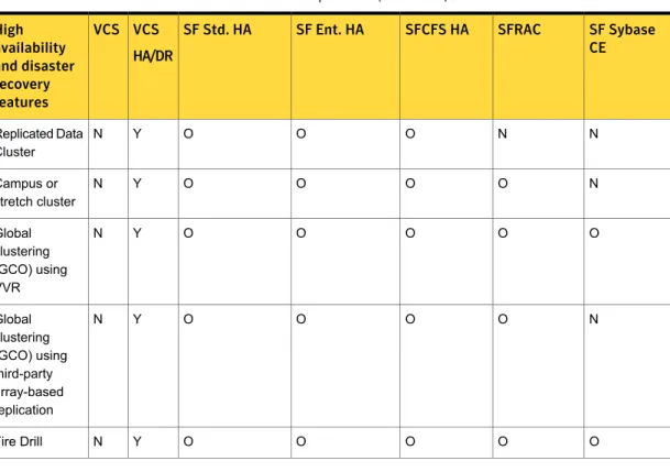
Table 1-3lists high availability and disaster recovery features available in SFHA Solutions products.
Table 1-3 High availability and disaster recovery feature support in SFHA Solutions products
SF Sybase CE SFRAC
SFCFS HA SF Ent. HA
SF Std. HA VCS HA/DR VCS High availability and disaster recovery features Y Y Y Y Y Y Y Clustering for high availability (HA) Y Y Y Y Y Y Y Database and application/ISV agents Y Y Y Y Y Y Y Advanced failover logic Y Y Y Y Y Y Y Data integrity protection with I/O fencing Y Y Y Y Y Y Y Advanced virtual machines support N Y Y Y Y Y Y Virtual Business Services O O O O O Y N Replication agents for VVR
N O O O O Y N Replication agents for third-party array-based replication 33 About supported disaster recovery scenarios
Table 1-3 High availability and disaster recovery feature support in SFHA Solutions products (continued)
SF Sybase CE SFRAC
SFCFS HA SF Ent. HA
SF Std. HA VCS HA/DR VCS High availability and disaster recovery features N N O O O Y N Replicated Data Cluster N O O O O Y N Campus or stretch cluster O O O O O Y N Global clustering (GCO) using VVR N O O O O Y N Global clustering (GCO) using third-party array-based replication O O O O O Y N Fire Drill
■ Y=Feature is included in your license.
■ O=Feature is not included in your license but may be licensed separately. ■ N=Feature is not supported with your license.
The following SFHA Solutions products support multiple third-party replication options:
■ Veritas Cluster Server (VCS)
■ Veritas Storage Foundation High Availability (SFHA)
■ Veritas Storage Foundation Cluster File System High Availability (SFCFSHA) ■ Veritas Storage Foundation for Oracle RAC (SF Oracle RAC)
Veritas Storage Foundation for Sybase CE supports VVR replication only at this time.
For current information on third-party replication support:
34 About supported disaster recovery scenarios
See:https://sort.symantec.com/agentsand selectReplication AgentsunderAgent
type.
Table 1-4 Replication support for databases across SFHA Solutions 6.0.1 products
SF Syb CE SFRAC
SFCFS HA SF Ent. HA
SF Std. HA VCS HA/DR VCS Database replication support N N Y Y Y Y Y DB2 N Y Y Y Y Y Y Single instance Oracle N Y N N N N N Oracle RAC N N Y Y Y Y Y Sybase Y N Y Y Y Y Y Syabase ASE CE
Single instance Oracle and Oracle RAC replication support includes Storage Foundation for Databases (SFDB) tools replication support.
Replication agent support in virtual environments
All VCS supported replication agents which are listed on SORT are supported inside the guest (virtual to virtual clustering). The in-guest support matrix for replication agent is the same as the VCS support matrix. If VCS is supported inside a guest on a virtualization platform, then the replication agent is also supported.Supported Linux virtualization technologies:
■ Kernel-based Virtual Machine (KVM) technology for Red Hat Enterprise Linux (RHEL) and SUSE Linux Enterprise Server (SLES)
■ Red Hat Enterprise Virtualization (RHEV) ■ Microsoft Hyper-V
■ Oracle Virtual Machine (OVM)
Pre-requisite for replication agent support in virtual environments:
Data disks must be made visible to the guest as pass-through devices, such as VMware to RDM, LDOM to Physical Disk or Disk Lun without slice option. Exception:
35 About supported disaster recovery scenarios
Firedrill functionality is not supported in virtual environments for the following replication agents:
■ EMC MirrorView ■ HP-UX EVA CA
Only Firedrill functionality is affected: these replication agents can be used to manage replication inside guests.
36 About supported disaster recovery scenarios
Planning for disaster
recovery
This chapter includes the following topics: ■ Planning for cluster configurations ■ Planning for data replication
Planning for cluster configurations
Storage Foundation and High Availability Solutions provides various disaster recovery configurations, such as campus clusters, global clusters for multi-site clusters. In multi-site clusters, the nodes can be placed in different parts of a building, in separate buildings, or in separate cities. The distance between The nodes depends on The type of disaster from which protection is needed and on The technology used to replicate data. Storage Foundation and High Availability supports various replication technologies for data replication.
To protect clusters against outages caused by disasters, the cluster components must be geographically separated.
Planning a campus cluster setup
A campus cluster is also known as a stretch cluster or remote mirror configuration. In a campus cluster, the hosts and storage of a cluster span multiple sites separated by a few miles.
Keep in mind the following best practices when you configure a Storage Foundation campus cluster:
■ Campus cluster sites are typically connected using a redundant high-capacity network that provides access to storage and private network communication
2
between the cluster nodes. A single DWDM link can be used for both storage and private network communication.
■ Tag the disks or enclosures that belong to a site with the corresponding VxVM site name. VxVM allocates storage from the correct site when creating or resizing a volume and when changing a volume’s layout if the disks in the VxVM disk group that contain the volume are tagged with the site name.
■ Tag each host with the corresponding VxVM site name. Make sure the read policy of the volumes is set toSITEREAD. This setting ensures that the reads on
the volumes are satisfied from the local site’s plex.
■ Turn on theallsitesattribute for all volumes that have data required by the application, to make sure they are evenly mirrored. Each site must have at least one mirror of all volumes hosting application data, including the FlashSnap log volume.
■ Turn on thesiteconsistentattribute for the disk groups and the volumes to
enable site-aware plex detaches. Snapshot volumes need not be site-consistent. ■ In the case of a two-site campus cluster, place the third coordinator disk on the
third site. You may use iSCSI disk on the third site as an alternative to Dark Fiber connected FC-SAN or a Coordination Point Server (CPS), as a third coordination point.
■ Make sure that a DCO log version 20 or higher is attached to the volumes to enable Fast Resync operations.
■ Set the CVM disk detach policy asglobalorlocalfor all disk groups containing data volumes.
For OCR and voting disk, it is recommended to have the disk group policy as
localdetach policy.
Planning a replicated data cluster setup
The VCS replicated data cluster (RDC) configuration allows you to provide a robust and easy-to manage disaster recovery protection for your applications. For example you can convert a single instance database configured for local high availability in a VCS cluster to a disaster-protected RDC infrastructure using Veritas Volume Replicator or a supported third-party replication technology to replicate changed data.
Keep in mind the following best practicies when you configure an RDC: ■ Make sure the sites and systems at each site are identified correctly for use
when defining system zones in an RDC.
■ Make sure there are dual dedicated LLT links between the replicated nodes.
38 Planning for disaster recovery
■ Since the sites used in the RDC configuration are within metro limits,
synchronous replication is typically used. Make sure the replication technology that you plan to use supports synchronous replication mode.
The RDC can also be configured using supported third-party replication technologies. See“Planning for data replication”on page 39.
Planning a global cluster setup
Global clusters provide the ability to fail over applications between geographically distributed clusters when a disaster occurs.
Global clustering involves two steps: 1. Replication of data between the sites
2. Configuring VCS clusters at the geographically distant sites and establishing a global cluster connection between them
The following aspects need to be considered when you design a disaster recovery solution:
■ The amount of data lost in the event of a disaster (Recovery Point Objective) ■ The acceptable recovery time after the disaster (Recovery Time Objective)
Planning for data replication
When planning for data replication, it is important to review the various hardware and software replication technologies and to review important considerations including the required level of data throughput.
Data replication options
Disaster recovery solutions support various hardware and software replication technologies.
■ Hitachi True Copy ■ IBM Metro Mirror ■ IBM SVC ■ EMC Mirror View Examples of hardware
replication options
■ Veritas Volume Replicator (VVR) ■ Oracle Data Guard
Examples of software replication options
39 Planning for disaster recovery
A complete list of supported replication technologies is listed on the Symantec Web site:
https://sort.symantec.com/agents
Data replication considerations
When you choose a replication solution, one of the important factors that you need to consider is the required level of data throughput. Data throughput is the rate at which the application is expected to write data. The impact of write operations on replication are of more significance than that of the read operations.
In addition to the business needs discussed earlier, the following factors need to be considered while choosing the replication options:
■ Mode of replication ■ Network bandwidth
■ Network latency between the two sites
■ Ability of the remote site to keep up with the data changes at the first site
40 Planning for disaster recovery
Implementing campus
clusters
■ Chapter 3. Setting up campus clusters for VCS and SFHA ■ Chapter 4. Setting up campus clusters for SFCFS, SFRAC
2
Setting up campus clusters
for VCS and SFHA
This chapter includes the following topics:
■ About setting up a campus cluster configuration ■ Fire drill in campus clusters
■ About the DiskGroupSnap agent
■ About running a fire drill in a campus cluster
About setting up a campus cluster configuration
You must perform the following tasks to set up a campus cluster:■ Preparing to set up a campus cluster configuration ■ Configuring I/O fencing to prevent data corruption
■ Configuring VxVM disk groups for campus cluster configuration ■ Configuring VCS service group for campus clusters
Preparing to set up a campus cluster configuration
Before you set up the configuration, review the VCS campus cluster requirements. See“ VCS campus cluster requirements”on page 16.
To prepare to set up a campus cluster configuration
1
Set up the physical infrastructure.3
■ Set up access to the local storage arrays and to remote storage arrays on each node.
■ Set up private heartbeat network.
See“ Typical VCS campus cluster setup”on page 20.
2
Install VCS on each node to form a cluster with at least one node in each of the two sites.See theVeritas Cluster Server Installation Guidefor instructions.
3
Install VxVM on each node with the required licenses.See theVeritas Storage Foundation and High Availability Installation Guide
for instructions.
Configuring I/O fencing to prevent data corruption
Perform the following tasks to configure I/O fencing to prevent data corruption in the event of a communication failure.
See theVeritas Cluster Server Installation Guidefor more details.
To configure I/O fencing to prevent data corruption
1
Set up the storage at a third site.You can extend the DWDM to the third site to have FC SAN connectivity to the storage at the third site. You can also use iSCSI targets as the coordinator disks at the third site.
2
Set up I/O fencing.Configuring VxVM disk groups for campus cluster configuration
Follow the procedure to configure VxVM disk groups for remote mirroring. See theVeritas Storage Foundation Cluster File System High Availability Administrator's Guidefor more information on the VxVM commands.
43 Setting up campus clusters for VCS and SFHA
To configure VxVM disk groups for campus cluster configuration
1
Set the site name for each host:# vxdctl set site=sitename
The site name is stored in the /etc/vx/volboot file. Use the following command to display the site names:
# vxdctl list | grep siteid
2
Set the site name for all the disks in an enclosure:# vxdisk settag site=sitename encl:enclosure
To tag specific disks, use the following command:
# vxdisk settag site=sitename disk
3
Verify that the disks are registered to a site.# vxdisk listtag
4
Create a disk group with disks from both the sites.# vxdg -s init diskgroup siteA_disk1 siteB_disk2 layout=layout
5
Configure site-based allocation on the disk group that you created for each site that is registered to the disk group.# vxdg -g diskgroup addsite sitename
6
Configure site consistency on the disk group.# vxdg -g diskgroup set siteconsistent=on
7
Create one or more mirrored volumes in the disk group.# vxassist -g diskgroup make volume size layout=layout
With the Site Awareness license installed on all hosts, the volume that you create has the following characteristics by default:
44 Setting up campus clusters for VCS and SFHA
■ Theallsitesattribute is set toon; the volumes have at least one plex at
each site.
■ The volumes are automatically mirrored across sites. ■ The read policyrdpolis set tositeread.
■ The volumes inherit the site consistency value that is set on the disk group.
Configuring VCS service group for campus clusters
Follow the procedure to configure the disk groups under VCS control and set up the VCS attributes to define failover in campus clusters.
To configure VCS service groups for campus clusters
1
Create a VCS service group (app_sg) for the application that runs in the campus cluster.hagrp -add app_sg
hagrp -modify app_sg SystemList node1 0 node2 1 node3 2 node4 3
2
Set up the system zones. Configure the SystemZones attribute for the service group.hagrp -modify app_sg SystemZones node1 0 node2 0 node3 1 node4 1
3
Set up the group fail over policy. Set the value of the AutoFailOver attribute for the service group.hagrp -modify app_sg AutoFailOver 2
4
For the disk group you created for campus clusters, add a DiskGroup resource to the VCS service group app_sg.hares -add dg_res1 DiskGroup app_sg
hares -modify dg_res1 DiskGroup diskgroup_name hares -modify dg_res1 Enabled 1
5
Configure the application and other related resources to the app_sg service group.6
Bring the service group online.45 Setting up campus clusters for VCS and SFHA
Fire drill in campus clusters
Fire drill tests the disaster-readiness of a configuration by mimicking a failover without stopping the application and disrupting user access.
The process involves creating a fire drill service group, which is similar to the original application service group. Bringing the fire drill service group online on the remote node demonstrates the ability of the application service group to fail over and come online at the site, should the need arise.
Fire drill service groups do not interact with outside clients or with other instances of resources, so they can safely come online even when the application service group is online. Conduct a fire drill only at the remote site; do not bring the fire drill service group online on the node hosting the original application.
About the DiskGroupSnap agent
The DiskGroupSnap agent verifies the VxVM disk groups and volumes for site awareness and disaster readiness in a campus cluster environment. To perform a fire drill in campus clusters, you must configure a resource of type DiskGroupSnap in the fire drill service group.
Note:To perform fire drill, the application service group must be online at the primary site.
During fire drill, the DiskGroupSnap agent does the following:
■ For each node in a site, the agent correlates the value of the SystemZones attribute for the application service group to the VxVM site names for that node. ■ For the disk group in the application service group, the agent verifies that the
VxVM site tags are defined for the disk group.
■ For the disk group in the application service group, the agent verifies that the disks at the secondary site are not tagged with the same VxVM site name as the disks at the primary site.
■ The agent verifies that all volumes in the disk group have a plex at each site. See theVeritas Cluster Server Bundled Agents Reference Guidefor more information on the agent.
About running a fire drill in a campus cluster
This topic provides information on how to run a fire drill in campus clusters.46 Setting up campus clusters for VCS and SFHA