1U Rackmount Server
RS160-S5/PX4
User Guide
Copyright © 2008 ASUSTeK COMPUTER INC. All Rights Reserved.
No part of this manual, including the products and software described in it, may be reproduced, transmitted, transcribed, stored in a retrieval system, or translated into any language in any form or by any means, except documentation kept by the purchaser for backup purposes, without the express written permission of ASUSTeK COMPUTER INC. (“ASUS”).
ASUS provides this manual “as is” without warranty of any kind, either express or implied, including but not
limited to the implied warranties or conditions of merchantability or fitness for a particular purpose. In no event shall ASUS, its directors, officers, employees, or agents be liable for any indirect, special, incidental,
E3847
First Edition V1 June 2008
Contents
Contents ... iii
Notices ... vii
Safety information ... viii
About this guide ... ix
Chapter 1:
Product introduction
1.1 System package contents ... 1-2 1.2 Serial number label ... 1-2 1.3 System specifications ... 1-3 1.4 Front panel features ... 1-5 1.5 Rear panel features ... 1-5 1.6 Internal features ... 1-6 1.7 LED information ... 1-7
1.7.1 Front panel LEDs ... 1-7 1.7.2 LAN (RJ-45) LEDs ... 1-7 1.7.3 HDD status LED ... 1-8
Chapter 2:
Hardware setup
2.1 Chassis cover ... 2-2
2.1.1 Removing the front cover ...2-2 2.1.2 Removing the rear cover ...2-4 2.1.3 Installing the top cover ...2-5
2.2 Central Processing Unit (CPU) ... 2-6
2.2.1 Installing the CPU ...2-6 2.2.2 Installing the CPU heatsink and airduct ...2-9
2.3 System memory ... 2-10
2.3.1 Overview ...2-10 2.3.2 Memory mirroring and sparing technology ...2-12 2.3.3 Installing a DIMM ...2-15 2.3.4 Removing a DIMM ...2-15
2.4 Hard disk drives ... 2-16 2.5 Expansion slot ... 2-18
Contents
2.7 SAS backplane cabling ... 2-23 2.8 Removable components ... 2-24
2.8.1 System fans ...2-24 2.8.2 Power supply module ...2-27 2.8.3 Optical drive ...2-28 2.8.4 Motherboard ...2-29
Chapter 3:
Installation options
3.1 Rackmount rail kit items ... 3-2 3.2 Rack rails assembly ... 3-2 3.3 Attaching the rails to the rack ... 3-3 3.4 Rackmounting the server ... 3-4
Chapter 4:
Motherboard Info
4.1 Motherboard layout ... 4-2 4.2 Jumpers ... 4-4 4.3 Internal connectors ... 4-8
Chapter 5:
BIOS setup
5.1 Managing and updating your BIOS ... 5-2
5.1.1 Creating a bootable floppy disk ...5-2 5.1.2 AFUDOS utility ...5-3 5.1.3 ASUS CrashFree BIOS 3 utility ...5-6
5.2 BIOS setup program ... 5-7
5.2.1 BIOS menu screen ...5-8 5.2.2 Menu bar ...5-8 5.2.3 Navigation keys ...5-8 5.2.4 Menu items ...5-9 5.2.5 Sub-menu items ...5-9
Contents
5.3.3 Floppy A ...5-10 5.3.4 IDE Configuration ...5-11 5.3.5 Primary IDE Master/Slave ...5-12 5.3.6 System Information ...5-13 5.4 Advanced menu ... 5-15 5.4.1 CPU Configuration ...5-15 5.4.2 Chipset Configuration ...5-17 5.4.3 PCI/PnP Configuration ...5-21 5.4.4 USB Configuration ...5-23 5.4.5 Peripheral Configuration ...5-24 5.4.6 ACPI Configuration ...5-25 5.4.7 Power On Configuration ...5-26 5.4.8 Hardware Monitor ...5-27 5.5 Server menu ... 5-29 5.6 Security ... 5-31 5.7 Boot menu ... 5-33
5.7.1 Boot Device Priority ...5-33 5.7.2 Boot Settings Configuration ...5-34
5.8 Exit menu ... 5-35
Chapter 6:
RAID configuration
6.1 Setting up RAID ... 6-2
6.1.1 RAID definitions ... 6-2 6.1.2 Installing hard disk drives ... 6-2
6.2 LSI Corporation MPT Setup Utility ... 6-3
6.2.1 Integrated Mirroring (IM) volume ... 6-3 6.2.2 Integrated Mirroring Enhanced (IME) volume ... 6-7 6.2.3 Integrated Striping (IS) volume ... 6-9 6.2.4 Managing Arrays ...6-11 6.2.5 Viewing SAS Topology ... 6-15 6.2.6 Global Properties ... 6-16
Contents
7.2 Intel® chipset device installation ... 7-12 7.3 LAN driver installation ... 7-15 7.4 VGA driver installation... 7-19 7.5 Management applications and utilities installation ... 7-21
7.5.1 Running the support CD ...7-21 7.5.2 Drivers menu ...7-21 7.5.3 Management Software menu ...7-22 7.5.4 Utilities menu ...7-22 7.5.5 Contact information ...7-22
Notices
Federal Communications Commission Statement
This device complies with Part 15 of the FCC Rules. Operation is subject to the following two conditions:
• This device may not cause harmful interference, and
• This device must accept any interference received including interference that may cause undesired operation.
This equipment has been tested and found to comply with the limits for a Class A digital device, pursuant to Part 15 of the FCC Rules. These limits are designed to provide reasonable protection against harmful interference in a residential installation. This equipment generates, uses and can radiate radio frequency energy and, if not installed and used in accordance with manufacturer’s instructions, may cause harmful interference to radio communications. However, there is no guarantee that interference will not occur in a particular installation. If this equipment does cause harmful interference to radio or television reception, which can be determined by turning the equipment off and on, the user is encouraged to try to correct the interference by one or more of the following measures:
• Reorient or relocate the receiving antenna.
• Increase the separation between the equipment and receiver.
• Connect the equipment to an outlet on a circuit different from that to which the receiver is connected.
• Consult the dealer or an experienced radio/TV technician for help.
Canadian Department of Communications Statement
This digital apparatus does not exceed the Class A limits for radio noise emissions from digital apparatus set out in the Radio Interference Regulations of the Canadian Department of Communications.
WARNING! The use of shielded cables for connection of the monitor to the
graphics card is required to assure compliance with FCC regulations. Changes
or modifications to this unit not expressly approved by the party responsible for compliance could void the user’s authority to operate this equipment.
Safety information
Electrical Safety
• Before installing or removing signal cables, ensure that the power cables for the system unit and all attached devices are unplugged.
• To prevent electrical shock hazard, disconnect the power cable from the electrical outlet before relocating the system.
• When adding or removing any additional devices to or from the system, ensure that the power cables for the devices are unplugged before the signal cables are connected. If possible, disconnect all power cables from the existing system before you add a device.
• If the power supply is broken, do not try to fix it by yourself. Contact a qualified service technician or your dealer.
Operation Safety
• Any mechanical operation on this server must be conducted by certified or experienced engineers.
• Before operating the server, carefully read all the manuals included with the server package.
• Before using the server, make sure all cables are correctly connected and the power cables are not damaged. If any damage is detected, contact your dealer as soon as possible.
• To avoid short circuits, keep paper clips, screws, and staples away from connectors, slots, sockets and circuitry.
• Avoid dust, humidity, and temperature extremes. Place the server on a stable surface.
This product is equipped with a three-wire power cable and plug for the user’s
safety. Use the power cable with a properly grounded electrical outlet to avoid electrical shock.
About this guide
Audience
This user guide is intended for system integrators, and experienced users with at least basic knowledge of configuring a server.
Contents
This guide contains the following parts:
1. Chapter 1: Product Introduction
This chapter describes the general features of the server, including sections on front panel and rear panel specifications.
2. Chapter 2: Hardware setup
This chapter lists the hardware setup procedures that you have to perform when installing or removing system components.
3. Chapter 3: Installation options
This chapter describes how to install optional components into the barebone server.
4. Chapter 4: Motherboard information
This chapter gives information about the motherboard that comes with the server. This chapter includes the motherboard layout, jumper settings, and connector locations.
5. Chapter 5: BIOS information
This chapter tells how to change system settings through the BIOS Setup menus and describes the BIOS parameters.
6. Chapter 6: RAID configuration
This chapter tells how to change system settings through the BIOS Setup menus. Detailed descriptions of the BIOS parameters are also provided.
7 Chapter 7: Driver installation
This chapter provides instructions for installing the necessary drivers for different system components.
Conventions
To make sure that you perform certain tasks properly, take note of the following symbols used throughout this manual.
Typography
Bold text Indicates a menu or an item to select.
Italics Used to emphasize a word or a phrase.
<Key> Keys enclosed in the less-than and greater- than sign means that you must press the enclosed key.
Example: <Enter> means that you must press the Enter or Return key.
<Key1+Key2+Key3> If you must press two or more keys
simultaneously, the key names are linked with a plus sign (+).
Example: <Ctrl+Alt+D>
Command Means that you must type the command
exactly as shown, then supply the required item or value enclosed in brackets. Example: At the DOS prompt, type the command line: format A:/S
DANGER/WARNING: Information to prevent injury to yourself when trying to complete a task.
CAUTION: Information to prevent damage to the components when trying to complete a task.
NOTE: Tips and additional information to help you complete a task.
This chapter describes the general features of the chassis kit. It includes sections on front panel and rear panel specifications.
Chapter 1
1.2
Serial number label
Before requesting support from the ASUS Technical Support team, you must take note of the product’s serial number containing 12 characters such as xxxxxxxxxxxx. See the figure below.
1.1
System package contents
Check your system package for the following items.
*ASUS System Web-based Management
• If any of the above items is damaged or missing, contact your retailer.
• The system does not include a USB floppy drive. You may have to use a USB floppy drive when creating a SAS/SATA RAID driver disk. Refer to
Chapter 7 for details. Model Name RS160-S5/PX4
Chassis ASUS R11 1U Rackmount Chassis
Motherboard ASUS DSEB-DG/SAS/RS160-S5 Server Board
Component 1 x 650W Single Power Supply
1 x SATAII/SAS Backplane (ASUS BP4LX-R10)
with 1 x 1-port mini-SAS to 4-port SATA cable 4 x hot-swap HDD trays
1 x Riser Card with 1 x PCIe x16 slot
1 x Front I/O Board 2 x 28mm and 4 x 56mm fans
1 x Air Duct Accessories 2 x CPU Heatsinks
1 x RS160-S5/PX4 User’s Guide 1 x ASUS ASWM 2.0 User’s Guide
1 x RS160-S5/PX4 Support CD (including ASWM*) 1 x Bag of Screws
1 x AC Power Cable 1 x Fixed Rackmount Kit Optional Items CA eTrust Anti-virus Software CD
1.3
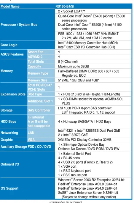
System specifications
The ASUS RS160-S5/PX4 is a server featuring the ASUS DSEB-DG/SAS server board. The server supports Intel® LGA771 Xeon® E5400 / E5300 / E5200 / E5100 Series processors with EM64T technology, plus other latest technologies through the chipsets onboard.
Model Name RS160-E4/SI
Processor / System Bus
2 x Socket LGA771
Quad-Core Intel® Xeon® E5400 (45nm) / E5300
series processors
Dual-Core Intel® Xeon® E5200 (45nm) / 5100
series processors
FSB 1600 / 1333 / 1066 / 667 MHz EM64T 2 x 2M, 4M, 8M, and 12M L2 cache
Core Logic IntelIntel®® 5400 Memory Controller Hub (MCH) 6321ESB I/O Controller Hub (ICH)
ASUS Features Smart FanASWM2.0 √√ Memory
Total Slots 8 (4-Channel) Capacity Maximum up to 32GB
Memory Type Fully-Buffered DIMM DDR2 800 / 667 / 533 Registered, ECC Memory Size 512MB, 1GB, 2GB and 4GB*
Expansion Slots
Total PCI/PCI-X/ PCI-E Slots 1
Slot Type 1 x PCIe x16 slot (Full-Height / Half-Length)
Additional Slot 1 1 x SO-DIMM socket for optional ASMB3-SOL PLUS Storage SAS Controller LSI 1068 PCI-X 8-port SAS controller: LSI® Integrated RAID 0, 1, 1E support
HDD Bays I = internal A or S will be
hot-swappable 4 x Hot-swap SAS/SATA II HDD Bays Networking LAN Intel2 x Intel® 6321 + Intel® 82573 GbE® 82563EB Dual Port GbE
Graphic VGA XGI Z9s PCI Display Controller 32MB
Auxiliary Storage FDD / CD / DVD 1 x Slim-type Optical Device BayOptions: No Device / DVD-ROM / DVD-RW
Onboard I/O
1 x External Serial Port
4 x RJ-45 ports
4 x USB 2.0 ports (Front x 2, Rear x 2) 1 x VGA port
*Specifications are subject to change without notice.
Anti-virus Software CA® eTrust™ 7.1 anti-virus software (Optional)
Management Solution
Out of Band Remote
Hardware ASMB3-SOL PLUS (Optional) Software ASUS ASWM 2.0
Dimension (HH x WW x DD) 686mm x 444mm x 43.4mm Net Weight Kg (CPU, DRAM &
HDD not inclu ded) 15 Kg
Power Supply 650W Single Power Supply
Environment
Operation temperature: 10°C ~ 35°C Non operation temperature: -40°C ~ 70°C Non operation humidity: 20% ~ 90% (
1.4
Front panel features
The barebone server displays a simple yet stylish front panel with easily accessible features. The power and reset buttons, LED indicators, optical drive, and two USB ports are located on the front panel.
Refer to section 1.7.1 Front panel LEDs for the LED descriptions.
1.5
Rear panel features
The rear panel includes the expansion slots, system power socket, and rear fans. The middle part includes the I/O shield with openings for the rear panel connectors on the motherboard.
The ports for the PS/2 keyboard, PS/2 mouse, USB, VGA, serial port, and Gigabit LAN do not appear on the rear panel if motherboard is not present.
Hot-swap HDD bays
Optical drive
Rack screw Rack screw
USB ports LAN2 LED HDD Access LED LAN1 LED Message LED Power button Power LED Location switch Reset button Location LED
PS/2 keyboard port USB ports Serial port VGA LAN port 3 / 4
port
Expansion slots
1.6
Internal features
The barebone server includes the basic components as shown.
• The barebone server does not include a floppy disk drive. Connect a USB floppy disk drive to any of the USB ports on the front or rear panel if you need to use a floppy disk.
• Only ASUS CD/DVD-ROMs fit the optical drive bay.
1. PCI Express x16 riser card bracket 2. Power fans 3. ASUS DSEB-DG/SAS/ RS160-S5 server board 4. Power supply 5. System fans
6. SATA II /SAS backplane (ASUS BP4LX-R10) 7. Hot-swap HDD tray 1 -
Connects to SATA1 port (Port 0)
8. Hot-swap HDD tray 2 - Connects to SATA1 port (Port 1)
9. Hot-swap HDD tray 3 - Connects to SATA1 port (Port 2)
10. Hot-swap HDD tray 4 - Connects to SATA1 port (Port 3)
11. Front I/O board (hidden) 12. Slim-type optical drive
1
2
3
4
5
6
7
8
9
10
11
12
5
5
5
5
5
1.7
LED information
1.7.1
Front panel LEDs
1.7.2
LAN (RJ-45) LEDs
Message LED LAN2 LED HDD Access LED LAN1 LED Power LED Location LEDLED Icon Display status Description
Power LED ON System power ON
HDD Access LED BlinkingOFF No activity Read/write data into the HDD Message LED BlinkingOFF System is normal; no incoming eventASWM indicates a HW monitor event Location LED OFF ON Normal status Location switch is pressed
(Press the location switch again to turn off)
LAN LEDs BlinkingOFF
ON
No LAN connection
LAN is transmitting or receiving data LAN connection is present
ACT/LINK LED SPEED LED
Status Description Status Description
OFF No link OFF 10 Mbps connection
GREEN Linked ORANGE 100 Mbps connection
BLINKING Data activity GREEN 1 Gbps connection SPEED LED
ACT/LINK LED SPEED LED ACT/LINK LED
1.7.3
HDD status LED
SATAII/SAS HDD LED Description HDD
Status LED
GREEN ON SATAII/SAS HDD power ON
RED ON SATAII/SAS HDD not present
RED Blinking(SAS only)
1. HDD has failed and should be swapped immediately (slow blinking,
2 times/sec)
2. RAID rebuilding (fast blinking, 10 times/sec)
HDD Activity
LED GREEN Blinking Read/write data from/into the SATAII/SAS HDD
HDD Status LED
This chapter lists the hardware setup procedures that you have to perform when installing or removing system components.
Chapter 2
Hardware se
2.1
Chassis cover
2.1.1
Removing the front cover
1. Use a Phillips screwdriver to remove the screw on each front end of the front cover.
3. Firmly hold the front cover and slide it toward the front panel for about half an inch until it is disengaged from the chassis.
2. Loosen the two thumbscrews on the rear panel to release the rear cover from the chassis.
6. Disconnect the LAN activity LED/ Locator LED cable and USB cable from the connectors under the front cover.
7. Disconnect the SATA cable and the power plug from the connectors on the back of the drive.
8. Leave the front cover aside. 5. Then push the front cover as arrow
2. Firmly hold the cover and slide it toward the rear panel for about half an inch until it is disengaged from the chassis.
3. Lift the cover from the chassis.
1/2 inch distance
1. Loosen the two thumbscrews on the rear panel to release the top cover from the chassis.
2.1.2
Removing the rear cover
1. Position the cover on top of the chassis with the thumbscrews on the rear, and leaving a gap of about half an inch from the front panel.
3. Slide the cover toward the front until it snaps in place. 4. Tighten the thumbscrews on the rear to secure the cover. 2. Make sure that the side markings
on the cover (two on each side) are aligned to the grooves on the chassis.
Grooves Side markings
2.1.3
Installing the top cover
2.2.1
Installing the CPU
To install a CPU:
1. Locate the CPU socket on the motherboard.
2.2
Central Processing Unit (CPU)
The motherboard comes with a surface mount LGA771 socket designed for the Intel® Xeon® Dual/Quad Core processor.
• Your boxed Intel® Xeon® LGA771 processor package should come with
installation instructions for the CPU and heatsink. If the instructions in this section do not match the CPU documentation, follow the latter.
• Upon purchase of the motherboard, make sure that the PnP cap is on the socket and the socket contacts are not bent. Contact your retailer immediately if the PnP cap is missing, or if you see any damage to the PnP
cap/socket contacts/motherboard components. ASUS will shoulder the cost of repair only if the damage is shipment/transit-related.
• Keep the cap after installing the motherboard. ASUS will process Return
Merchandise Authorization (RMA) requests only if the motherboard comes with the cap on the LGA771 socket.
• The product warranty does not cover damage to the socket contacts
resulting from incorrect CPU installation/removal, or misplacement/loss/
incorrect removal of the PnP cap.
• If you install only one CPU, install the CPU to the CPU2 socket only. The
system will not boot and the CPU warning LED will light up if a single CPU is installed on the CPU1 socket.
®
CPU1
3. Lift the load lever in the direction of the arrow to a 135º angle.
4. Lift the load plate with your thumb and forefinger to a 100º angle (A), then push the PnP cap from the load plate window to remove (B).
5. Position the CPU over the socket, making sure that the gold triangle is on the bottom-left corner of the socket. The socket
Load plate
A B
2. Press the load lever with your thumb (A), then move it to the left (B) until it is released from the retention tab.
Retention tab Load lever
This side of the socket box should face you.
PnP cap
A
B
To prevent damage to the socket pins, do not remove the PnP cap unless you are installing a CPU.
The CPU fits in only one correct orientation. DO NOT force the CPU into the socket to prevent bending the connectors on the socket and damaging the CPU!
6. Close the load plate (A), then push the load lever (B) until it snaps into the retention tab.
A
2. Carefully lower the airduct until it fits in place.
To install the airduct:
1. Position the airduct on top of the heatsink.
2. Twist each of the four screws with a Philips (cross) screwdriver just enough to attach the heatsink to the motherboard. When the four screws are attached, tighten them one by one to completely secure the heatsink.
2.2.2
Installing the CPU heatsink and airduct
To install the CPU heatsink:
1. Carefully place the heatsink on top of the installed CPU.
2.3
System memory
2.3.1
Overview
The motherboard features eight fully-buffered DIMM (FB-DIMM) sockets to support 240-pin FB-DIMM modules. You can purchase extra FB-DIMM modules based on your needs. An FB-DIMM module has a different pin-out from DDR2 DIMMs so you cannot install DDR2 DIMMs on an FB-DIMM socket. Note that an FB-DIMM socket has an Advanced Memory Buffer (AMB) chip that allows memory-to-CPU connection at gigabit speed.
The figure illustrates the location of the FB-DIMM sockets:
®
DSEB-DG/SAS/RS160-S5 240-pin FB-DIMM sockets DIMM_11 DIMM_10 112 Pins 128 Pins DIMM_21 DIMM_20 DIMM_31 DIMM_30 DIMM_01 DIMM_00
Rank population
DIMM 21 DIMM 20 DIMM 1 1 DIMM 10 DIMM 01 DIMM 00MCH
DIMM 31 DIMM 30DIMM installation reference table
DIMMs in pair means two DIMMs with the same configuration.
No. of
DIMMs Slot(s) to use Memory architecture
1 single DIMM DIMM_00 single channel
2 one pair DIMM_00, DIMM_10 dual-channel
4 two pairs (DIMM_00, DIMM_10) (DIMM_20, DIMM_30) Quadri-channel 6 three pairs (DIMM_00, DIMM_10) (DIMM_20, DIMM_30)
(DIMM_01, DIMM_11) Quadri-channel
8 four pairs (DIMM_00, DIMM_10) (DIMM_20, DIMM_30) (DIMM_01, DIMM_11) (DIMM_21, DIMM_31) Quadri-channel
2.3.2
Memory mirroring and sparing technology
The Intel® 5400 chipset supports the memory mirroring and sparing technology. Refer to the below sections:
Memory Mirroring:
When enabling memory mirroring function in the BIOS setting (please refer the section 4.4.2 Chipset Configuration and configure the option Memory Branch Mode as Branch Mirroring), Branch 1 contains a replicate copy of the data in Branch 0. The DIMMs must cover the same slot position on both branches. DIMMs that cover a slot position must be identical with respect to size, speed, and organization. DIMMs within a slot position must match each other, but aren’t required to match adjacent slot positions.
And the total memories size will be the half of all installed memories.
The below two memory configurations were required to operate in mirrored mode. 1. Configuration 1 (Mirroring): Four memories population
DIMM 00 (Slot 0:Channel 0)
MCH
Branch 0
DIMM 01 (Slot 1:Channel 0) DIMM 10 (Slot 0:Channel 1) DIMM 1
1 (Slot 1:Channel 1)
DIMM 20 (Slot 0:Channel 2) DIMM 21 (Slot 1:Channel 2) DIMM 30 (Slot 0:Channel 3) DIMM 31 (Slot 1:Channel 3)
Branch 1 (Mirror)
2. Configuration 2 (Mirroring) : Eight memories population
Branch0
Channel 0 Channel 1
DIMM_00
(1024MB*2 Ranks) (1024MB*2 Ranks)DIMM_10
Rank 0
(1024 MB) (1024 MB)Rank 1 (1024 MB)Rank 0 (1024 MB)Rank 1
Sparing
Memory space 1024 MB 1024 MB
Total Memory 2048 MB
The following tables show memory configurrations with Memory Sparing function in Branch 0.
One DIMM per channel (two ranks)
Memory Sparing :
At configuration time, a DIMM rank is set aside to replace a defective DIMM rank. When the error rate for a failing DIMM rank reaches a pre-determined threshold, the memory sparing function will issue an interrupt and initiate a spare copy. At the completion of the copy, the failing DIMM rank is disabled and the “spared” DIMM rank will be used in its place. Refer to 4.4.2 Chipset Configuration and configure the options of Branch Specific Sparing to enable the memory sparing functions. And the default BIOS setting is disabled.
• Each branch contains its own sparing engine and can be enabled or disabled separately.
• This motherboard does not support rank sparing across branches. • This motherboard does not support rank sparing when in mirror mode.
• The DIMM rank with the largest size will be assigned as spare rank. Data can only be copied from a smaller sized rank to a larger sized one.
• A DIMM can contain only one or two ranks. To support sparing function, a DIMM channel should contain at least two ranks.
• When sparing function is enabled, the usable memory size will reduce then size of the spare ranks.
Branch0
Channel 0 Channel 1
DIMM_00
(512MB*2 Ranks) (512MB*2 Ranks)DIMM_10 Rank 0
(512 MB) (512 MB)Rank 1 (512 MB)Rank 0 (512 MB)Rank 1 Sparing
Memory space 1024 MB 1024 MB
DIMM_01
(1024MB*2 Ranks) (1024MB*2 Ranks)DIMM_11 Rank 0
(1024 MB) (1024 MB)Rank 1 (1024 MB)Rank 0 (1024 MB)Rank 1 Sparing
Memory space 1024 MB 1024 MB
Total Memory 4096 MB
2.3.3
Installing a DIMM
Make sure to unplug the power supply before adding or removing DIMMs or other system components. Failure to do so may cause severe damage to both the motherboard and the components.
To install a DIMM:
1. Unlock a DIMM socket by pressing the retaining clips outward. 2. Align a DIMM on the socket
such that the notch on the DIMM matches the break on the socket. 3. Firmly insert the DIMM into the
socket until the retaining clips snap back in place and the DIMM is properly seated.
• A FB-DIMM is keyed with a notch so that it fits in only one direction. DO
NOT force a DIMM into a socket to avoid damaging the DIMM.
• The FB-DIMM sockets do not support DDR2 DIMMs. DO NOT install DDR2 DIMMs to the FB-DIMM sockets.
2.3.4
Removing a DIMM
To remove a DIMM:
1. Simultaneously press the retaining clips outward to unlock the DIMM.
2. Remove the DIMM from the socket.
Support the DIMM lightly with
your fingers when pressing
the retaining clips. The DIMM might get damaged when it
flips out with extra force.
FB-DIMM notch
1
1
2
3
1
1
2
2.4
Hard disk drives
The system supports four hot-swap SATAII/SAS hard disk drives. The hard disk drive installed on the drive tray connects to the motherboard SATAII/SAS ports via the SATAII/SAS backplane.
To install a hot-swap SATAII/SAS HDD: 1. Release a drive tray by pushing the
spring lock to the right, then pulling the tray lever outward. The drive tray ejects slightly after you pull out the lever.
2. Firmly hold the tray lever and pull the drive tray out of the bay.
3. Take note of the drive tray holes. Each side has three holes to fit different types of hard disk drives. Use two screws on each side to secure the hard disk drive.
5. Carefully insert the drive tray and push it all the way to the depth of the bay until just a small fraction of the tray edge protrudes.
6. Push the tray lever until it clicks, and secures the drive tray in place. The drive tray is correctly placed when its front edge aligns with the bay edge.
7. Repeat steps 1 to 6 if you wish to install a second SATAII/SAS drive.
When installed, the SATAII/SAS connector on the drive connects to the SATAII/
SAS interface on the backplane.
8. Connect the bundled SATAII/SAS cables to the connectors on the SATAII/ SAS backplane. Refer to section 2.7 SATAII/SAS backplane cabling for information on the SATAII/SAS backplane cable connections.
PCI Express x16 slot
2.5
Expansion slot
2.5.1
Installing an expansion card to the riser card bracket
The barebone server comes with a riser card bracket. You need to remove the bracket if you want to install PCI Express x16 expansion cards.
To install a PCI Express x16 card:
3. Place the riser card bracket on a flat and stable surface, then remove the screw from the slot bay. 2. Firmly hold the riser card bracket,
and then pull it up to detach it from the PCI Express x16 slot on the motherboard.
4. Install a PCI Express x16 card to the bracket as shown, then secure the card with a screw.
2.5.2
Reinstalling the riser card bracket
To reinstall the riser card bracket:
1. Take note of the holes on the riser card bay. The two pegs on the riser card bracket should match these holes to ensure that the bracket is properly in place.
Pegs on the riser card bracket
2. Align the riser card bracket with the expansion card to the PCI Express x16 slot on the motherboard. 3. Press the riser card bracket until
the golden connectors completely fit the slot and the bracket aligns with the rear panel.
4. Secure the riser card bracket with a screw.
5. Connect the cable(s) to the card, if applicable.
2.5.3
Configuring an expansion card
After installing the expansion card, configure the it by adjusting the software settings.
1. Turn on the system and change the necessary BIOS settings, if any. See Chapter 5 for information on BIOS setup.
2. Assign an IRQ to the card. Refer to the following tables. 3. Install the software drivers for the expansion card.
* These IRQs are usually available for ISA or PCI devices.
Standard Interrupt assignments
IRQ Priority Standard function
0 1 System Timer
1 2 Keyboard Controller
2 - Programmable Interrupt
3* 11 Communications Port (COM2)
4* 12 Communications Port (COM1)
5* 13
--6 14 Floppy Disk Controller
7* 15
--8 3 System CMOS/Real Time Clock
9* 4 ACPI Mode when used
10* 5 IRQ Holder for PCI Steering
11* 6 IRQ Holder for PCI Steering
12* 7 PS/2 Compatible Mouse Port
13 8 Numeric Data Processor
14* 9 Primary IDE Channel
2.6
Cable connections
Pre-connected system cables
1. 24-pin SSI power connector (from power supply to motherboard) 2. 4-pin/8-pin SSI power connector (from power supply to motherboard) 3. SAS backplane power connector (from power supply)
4. System fan connectors (from motherboard FRNT_FAN1-3 and CPU_FAN1-2 to system fans)
1
2
3
5
4
6
2
4
4
7
8
2.7
SAS backplane cabling
Connect the SAS HDDs
Connects a 8-pin plug from power supply
Connects the SATA cable from SAS1 port on the MB
Connects the SATA cable from SAS1 port on the MB
Connects the SATA cable from SAS1 port on the MB
Connects the SAS cable from SAS1 port on the MB
2.8
Removable components
You may need to remove previously installed system components when installing or removing system devices, or when you need to replace defective components. This section tells how to remove the following components:
1. System fans 2. Power supply module 3. Optical drive 4. Motherboard
2.8.1
System fans
The system comes with:
• four units of 40 mm * 56 mm 15500 rpm fans • two unit of 40 mm * 28 mm 15500 rpm fans
Refer to the illustration below for location of the system fans.
40 mm x 28 mm system fan 40 mm x 56 mm system fans
2. Lift the fan, then set aside. 3. Repeat step 1 to 2 to uninstall the
other system fans.
To uninstall the side system fans 1. Disconnect the system fan
cable from the connector on the motherboard.
2. Lift the fan, then set aside. To uninstall the center system fans 1. Disconnect the system fan cables
from the fan connectors on the motherboard.
You may need to remove the
riser card bracket for easier system fan cable disconnection.
To reinstall the side system fan 1. Insert the fan to the fan cage. The
airflow directional arrow on the fan side should point towards the rear panel.
2. Connect the system fan cable to the fan connector on the the motherboard.
To reinstall the center system fans 1. Insert the fan to the fan cage. The
airflow directional arrow on the fan side should point towards the system rear panel.
2. Connect the system fan cable to the fan connector on the motherboard.
2.8.2
Power supply module
To uninstall the power supply module 1. Disconnect all the power cables
connected to the motherboard and other system devices.
4. Slide the power supply forward for about half an inch, then carefully lift it out from the chassis. 3. From the rear panel, remove the
two screws that secure the power supply from the chassis.
2. Use a Phillips (cross) screwdriver to remove the screws that secure the front end of the power supply.
2.8.3
Optical drive
To uninstall the slim optical drive
1. Follow step 1 to 8 of section 2.1.1 Removing the front cover to remove the front cover from the barebone server.
4. Carefully slide the optical drive inward for about half an inch, then lift it out of the bay.
5. Remove the screws that secure the optical drive to its metal bracket. 2. Use a Phillips screwdriver (cross)
to remove the three screws that secure the drive.
3. Use a Phillips screw driver (cross) to remove the two screws that secure the backplane with the drive. Then, remove the backplane from the drive.
2.8.4
Motherboard
To uninstall the motherboard
1. Disconnect all the pre-connected cables from the motherboard. See section
2.6 Cable connections for details.
2. Uninstall all the devices from the motherboard including the CPU and heatsink, riser card bracket, and DDR DIMMs. Refer to the corresponding sections for instructions on removing these components.
3. Use a Philips (cross) screwdriver to remove the screws that secure the motherboard to the base of the chassis.
Refer to the illustration below for the location of the motherboard screws.
4. Carefully lift the motherboard out of the chassis as shown.
To reinstall the motherboard: 1. Firmly hold the motherboard by
the sides and insert it into the chassis as shown.
2. Carefully adjust the motherboard until the rear panel ports fit in place.
3. Use a Phillips (cross) screwdriver to secure the motherboard with nine (9) screws in the holes as shown in the illustration in the previous section.
4. Reconnect all the required cables to the motherboard. See section
2.6 Cable connections for details.
5. Reinstall all the devices that you have previously removed.
This chapter describes how to install the optional components and devices into the barebone server.
Chapter 3
Installation
opt
3.1
Rackmount rail kit items
If you have the rackmount rail kit, it contains two pairs of rails (one pair for each side of the barebone system), and eight (8) pairs of nut-and-bolt type screws.
3.2
Rack rails assembly
To assemble the rack rails:
1. Determine the depth of the rack where you wish to install the system. 2. Match one long and one short rail to your desired length, and fix them
together using four (4) pairs of nuts and bolts. 3. Repeat step 2 to assemble the other rail pair.
Nuts Bolts
Left pair
Right pair
3.3
Attaching the rails to the rack
To attach the rails to the rack:
1. Select one unit of space (1U) on the rack where you wish to install the barebone server.
2. Remove the screws from the 1U space on the rack front.
5. Find the rear 1U space that corresponds to the front 1U space where you attached the rail.
6. Remove the screws from the rear 1U space, and align the rear end holes. 7. Drive in two screws on the outer holes to secure the rear end.
8. From the rack front, find the corresponding 1U space for the second rail pair. 9. Repeat steps 2 to 7 to attach the second rail pair. When properly installed,
the rack rails appear as shown.
3. Align the front end holes of a rack rail pair to the 1U space.
4. Drive in two screws on the outer holes to secure the front end.
3.4
Rackmounting the server
To mount the server to the rack:
1. Firmly hold the server on both sides and insert the rear panel side to the front end of the rack rail, then carefully push the server all the way to the back until the front panel fits the front end of the rack, and the rack screws on the server match the middle hole on the rack..
2. Tighten the two rack screws to secure the server to the rack.
Chapter 4
Motherboa
rd info
This chapter includes the motherboard layout, and brief descriptions of the jumpers and internal connectors.
4.1
Motherboard layout
DSEB-DG/SAS/RS160-S5 Server Board
8Mb FWH ® FLOPPY1 BUZZER1 COM2 Super I/O CR2032 3V Lithium Cell CMOS Power PANEL1 PS/2 T: Mouse B: Keyboard USB12_L31 LAN12 ATX12V1 CPU_FAN1 Intel® 6321ESB Intel® 5400 PSUSMB1 AUX_PANEL1 HDLED1 USB34 REAR_F AN1 DSEB-DG/SAS/RS160-S5 ASMB3-SOL PLUS PCIE1 33cm (13in) 30.5cm (12in) CPU1 COM1 VGA1 CPU2 PCIX6 REAR_F AN2 ATX12V2 CPU_FAN2 PRI_IDE1 SA TA 5 SA TA 6 SAS2 SAS1 CLRTC1 RECOVERY1 FRNT_FAN1 FRNT_FAN2 VGA_EN1 LAN_EN1 Intel 82573L SB_PWR1 PCIX5 LAN34 ATXPWR1
DDR FB-DIMM_31 (64/72 bit, 240-pin module) DDR FB-DIMM_30 (64/72 bit, 240-pin module)
PCI2 PCIE3 SATA 3 SA TA 4 SA TA 1 SA TA 2 Intel 82573L Intel 82563EB XGI Volari Z9s FRNT_FAN3 FRNT_FAN4 FAN_SEL1 FAN_SEL2 LAN_EN4
DDR FB-DIMM_01 (64/72 bit, 240-pin module) DDR FB-DIMM_00 (64/72 bit, 240-pin module) DDR FB-DIMM_11 (64/72 bit, 240-pin module) DDR FB-DIMM_10 (64/72 bit, 240-pin module) DDR FB-DIMM_21 (64/72 bit, 240-pin module) DDR FB-DIMM_20 (64/72 bit, 240-pin module)
PCIE4 LSI SAS1068 SASLED1 SAS_EN1LED1 LAN_EN3 LPC1 RAID_SEL1 FBD_FAN1
Layout contents
Jumpers Page
1. Clear RTC RAM (CLRTC1) 4-4
2. VGA controller setting (3-pin VGA_SW1) 4-5
3. LAN controller setting (3-pin LAN_EN1, LAN_EN3, LAN_EN4) 4-5
4. Fan control setting (3-pin CPUFAN_SET1, CHAFAN_SET1) 4-6
5. Onboard storage setting (3-pin SAS_EN1) 4-6
6. Force BIOS recovery setting (3-pin RECOVERY1) 4-7
Internal connectors Page
1. Floppy disk drive connector (34-1 pin FLOPPY1) 4-8
2. Serial ATA connectors (7-pin SATA1-6) 4-8
3. IDE connector (40-1 pin PRI_IDE1 4-9
4. SAS connectors 4-10
5. SAS LSI1068 ports LED connector (18-1 pin SASLED1) 4-11
6. Hard disk activity LED connector (4-pin HDLED1) 4-11
7. USB connectors (10-1 pin USB34) 4-12
8. CPU and system fan connectors (4-pin CPU_FAN1/2,
REAR_FAN1/2, FRNT_FAN1/2/3/4) 4-12
9. Serial port connectors (10-1 pin COM2) 4-13
10. Power supply SMBus connector (5-pin PSUSMB1) 4-13
11. SSI power connectors (24-pin ATXPWR1, 8-pin ATX12V1,
4-pin ATX12V2) 4-14
12. System panel connector (20-1 pin PANEL1) 4-15 13. Auxiliary panel connector (20-pin AUX_PANEL1) 4-16
4.2
Jumpers
1. Clear RTC RAM (CLRTC1)This jumper allows you to clear the Real Time Clock (RTC) RAM in CMOS. You can clear the CMOS memory of date, time, and system setup parameters by erasing the CMOS RTC RAM data. The onboard button cell battery powers the RAM data in CMOS, which include system setup information such as system passwords.
Except when clearing the RTC RAM, never remove the cap on CLRTC jumper
default position. Removing the cap will cause system boot failure!
If the steps above do not help, remove the onboard battery and move the jumper again to clear the CMOS RTC RAM data. After the CMOS clearance, reinstall the battery.
®
DSEB-DG Series/SAS/RS160-S5 Clear RTC RAM
CLRTC1
Normal
(Default) Clear CMOS
1
2 23
To erase the RTC RAM:
1. Turn OFF the computer and unplug the power cord.
2. Move the jumper cap from pins 1–2 (default) to pins 2–3. Keep the cap on pins 2–3 for about 5–10 seconds, then move the cap back to pins 1–2. 3. Plug the power cord and turn ON the computer.
4. Hold down the <Del> key during the boot process and enter BIOS setup to re-enter data.
2. VGA controller setting (3-pin VGA_EN1)
This jumper allows you to enable or disable the onboard VGA controller. Set to pins 1–2 to activate the VGA feature.
3. LAN controller setting (3-pin LAN_EN1, LAN_EN3, LAN_EN4)
These jumpers allow you to enable or disable the onboard Intel® 82563EB
Gigabit LAN controller and the onboard Intel® 82573L Gigabit LAN controllers.
Set to pins 1-2 to activate the Gigabit LAN feature.
®
DSEB-DG/SAS/RS160-S5 VGA setting
VGA_EN1 1 2 2 3 Enable (Default) Disable ® DSEB-DG/SAS/RS160-S5 LAN setting LAN_EN1 1 2 2 3 Enable (Default) Disable 1 2 23 Enable (Default) Disable LAN_EN3 1 2 23 Enable (Default) Disable LAN_EN4
4. Fan control setting (3-pin CPUFAN_SET1, CHAFAN_SET1)
These jumpers allow you to switch for fan pin selection. The CPUFAN_SET1 jumper is for the CPU fans control and CHAFAN_SET1 is for the other fans control including front fans, rear fans and FB-DIMM fans. Set to pins 1–2 for 4-pin fans or pins 2–3 for 3-pin fans.
5. Onboard storage setting (3-pin SAS_EN1)
This jumper allows you to enable or disable the onboard LSI1068 SAS controller. Set the jumper to pins 1–2 to enable the SAS function (default).
• If you use a 4-pin fan but set the jumper to pin 2–3, the fan you installed
may not work.
• If you use a 3-pin fan but set the jumper for a 4-pin fan, the fan control will not work and the fan you installed will always run at full speed.
®
DSEB-DG/SAS/RS160-S5 FAN setting
FAN_SET1 FAN_SET2 1 2 2 3 Balanced (Default) DC FAN ® SAS_EN1
6. Force BIOS recovery setting (3-pin RECOVERY1)
This jumper allows you to quickly update or recover the BIOS settings when it becomes corrupted.
To update the BIOS:
1. Prepare a floppy disk that contains the original or latest BIOS for the motherboard (DSEB-DG.ROM) and the AFUDOS.EXE utility. 2. Set the jumper to pins 2–3.
3. Insert the floppy disk then turn on the system to update the BIOS. 4. Shut down the system.
5. Set the jumper back to pins 1–2. 6. Turn on the system.
®
DSEB-DG/SAS/RS160-S5 BIOS recovery setting RECOVERY1
(Default)Normal BIOS Recovery
4.3
Internal connectors
1. Floppy disk drive connector (34-1 pin FLOPPY1)This connector is for the provided floppy disk drive (FDD) signal cable. Insert one end of the cable to this connector, then connect the other end to the signal connector at the back of the floppy disk drive.
Pin 5 on the connector is removed to prevent incorrect cable connection when using a FDD cable with a covered Pin 5.
®
NOTE: Orient the red markings on
the floppy ribbon cable to PIN 1.
FLOPPY1
DSEB-DG/SAS/RS160-S5 Floppy disk drive connector PIN1
2. Serial ATA connectors
(7-pin SATA1, SATA2, SATA3, SATA4, SATA5, SATA6 )
These connectors are for the Serial ATA signal cables for Serial ATA hard disk drives. ® SATA2 SATA1 SATA4 SATA3 GND RSATA_TXP1 RSATA_TXN1 GND RSATA_RXN1 RSATA_RXP1 GND GND RSATA_TXP2 RSATA_TXN2 GND RSATA_RXN2 RSATA_RXP2 GND GND RSATA_TXP3 RSATA_TXN3 GND RSATA_RXN3 RSATA_RXP3 GND RSATA_TXP4 RSATA_TXN4 GND RSATA_RXN4 RSATA_RXP4
3. IDE connector (40-1 pin PRI_IDE1)
This connector is for an Ultra DMA 100/66 signal cable. The Ultra DMA 100/66 signal cable has three connectors: a blue connector for the primary IDE connector on the motherboard, a black connector for an Ultra DMA 100/66 IDE slave device (optical drive/hard disk drive), and a gray connector for an Ultra DMA 100/66 IDE master device (hard disk drive). If you install two hard disk drives, you must configure the second drive as a slave device by setting its jumper accordingly. Refer to the hard disk documentation for the jumper settings.
• Pin 20 on the IDE connector is removed to match the covered hole on the
Ultra DMA cable connector. This prevents incorrect insertion when you connect the IDE cable.
• Use the 80-conductor IDE cable for Ultra DMA 100/66 IDE devices.
®
DSEB-DG/SAS/RS160-S5 IDE connector
PRI_IDE1 PIN1
4. SAS connectors
This motherboard comes with two Serial Attached SCSI (SAS) connectors, the next-generation storage technology that supports both Series SCSI and Serial ATA (SATA). Each connector supports one device.
®
DSEB-DG/SAS/RS160-S5 MINI SAS connectors
To connect the SAS cable:
Plug in the SAS cable to the SAS connector until the cable lock snaps in place.
1
2 To disconnect the SAS cable: 1. With your thumb, push down the
cable lock to release. 2. While still keeping your
thumb’s grip on the cable lock, carefully pull away the cable from the connector.
5. SAS LSI1068 ports LED connector (18-1 pin SASLED1)
This connector is for the front panel LED port indicator that shows the SAS HDD status.
®
DSEB-DG/SAS/RS160-S5 SASLED connector
SASLED1 ACT_LED 0 FL T_LED0 PIN1 ACT_LED 1 FL T_LED1 ACT_LED 2 FL T_LED2 ACT_LED 3 FL T_LED3 ACT_LED 4 GN D ACT_LED 5 FL T_LED4 FL T_LED5 ACT_LED 6 FL T_LED6 ACT_LED 7 FL T_LED7
6. Hard disk activity LED connector (4-pin HDLED1)
This connector is used to connect to a hard disk drive active LED connector on the SAS or RAID card.
®
DSEB-DG/SAS/RS160-S5 storage card activity LED connector HDLED1
7. USB connector (10-1 pin USB34)
This connector is for USB 2.0 ports. Connect the USB module cable to this connector, then install the module to a slot opening at the back of the system chassis. This USB connector complies with USB 2.0 specification that supports up to 480 Mbps connection speed.
The USB port module is purchased separately.
®
DSEB-DG/SAS/RS160-S5 USB connector USB34
PIN1
Powe
r
USB PortA(-) USB PortA(+
)
GND
Powe
r
USB PortB(-) USB PortB(+
)
GND NC
8. CPU and system fan connectors (4-pin CPU_FAN1/2, REAR_FAN1/2, FRNT_FAN1/2/3/4)
The fan connectors support cooling fans of 350 mA ~ 740 mA (8.88 W max.) or a total of 3.15 A ~ 6.66 A (53.28 W max.) at +12V. Connect the fan cables to the fan connectors on the motherboard, making sure that the black wire of each cable matches the ground pin of the connector.
CPU_FAN1 CPU_FAN2 REAR_FAN1 REAR_FAN2 GND FAN Power FAN Spee d PWM Contro l CPU_FAN1 CPU_FAN2 REAR_FAN1 REAR_FAN2 FRNT_FAN1 FRNT_FAN2 GN D
FAN Power FAN Speed PWM Contro
l
r
d FAN PowerFAN Speed PWM Control FBD_FAN1 GND FAN Power FAN Speed FBD_FAN1
9. Serial port connector (10-1 pin COM2)
This connector is for a serial (COM) port. Connect the serial port module cable to this connector, then install the module to a slot opening at the back of the system chassis.
The serial port module is purchased separately.
®
DSEB-DG/SAS/RS160-S5 Serial port connectors
PIN 1
COM2
10. Power supply SMBus connector (5-pin PSUSMB1)
This connector is for the power supply SMB cable, if your power supply supports the SMBus function.
®
DSEB-DG/SAS/RS160-S5 Power supply SMBus connector PSUSMB1 +3.3V Remote Sense GND NC I2C_7_D AT A# I2C_7_CLK #
11. SSI power connectors (24-pin ATXPWR1, 8-pin ATX12V1, 4-pin ATX12V2)
These connectors are for SSI power supply plugs. The power supply plugs are designed to fit these connectors in only one orientation. Find the proper orientation and push down firmly until the connectors completely fit.
• For a fully configured system, we recommend that you use an SSI 12 V-compliant power supply unit (PSU) for LGA771-socket Intel® Xeon
Dual Core processors (Bensley platform).
• DO NOT forget to connect the 24+8+4-pin power plugs; otherwise, the
system will not boot up.
• Use of a PSU with a higher power output is recommended when configuring
a system with more power consuming devices. The system may become unstable or may not boot up if the power is inadequate.
• You must install a PSU with a higher power rating if you intend to install
additional devices. ® +12V DC GND +12V DCGND DSEB-DG/SAS/RS160-S5 ATX power connectors
8-pin GND 12V2 GND 12V2 GND 12V1 GND 12V1
24-pin Power ConnectorATXPWR1
ATX12V1 4-pin ATX12V2 +3 Vo lts +3 Vo lts Ground +5 Vo lts +5 Vo lts
Ground Ground Power OK +5V Standby +12
Vo lts -5 Vo lts +5 Vo lts +3 Vo lts -1 2 Vo lts
Ground PSON Ground Ground
# Ground +5 Vo lts +12 Vo lts +3 Vo lts +5 Vo lts Ground
12. System panel connector (20-pin PANEL1)
This connector supports several chassis-mounted functions.
The system panel connector is color-coded for easy connection.
1. System power LED (Green 3-pin PLED)
This 3-pin connector is for the system power LED. Connect the chassis power LED cable to this connector. The system power LED lights up when you turn on the system power, and blinks when the system is in sleep mode.
2. Message LED (Brown 2-pin MLED)
This 2-pin connector is for the message LED cable that connects to the front message LED. The message LED is controlled by Hardware monitor to indicate an abnormal event occurance.
3. System warning speaker (Orange 4-pin SPEAKER)
This 4-pin connector is for the chassis-mounted system warning speaker. The speaker allows you to hear system beeps and warnings.
4. Hard disk drive activity LED (Red 2-pin IDE_LED)
This 2-pin connector is for the HDD Activity LED. Connect the HDD Activity LED cable to this connector. The IDE LED lights up or flashes when data is read from or written to the HDD.
5. ATX power button/soft-off button (Green 2-pin PWRSW)
This connector is for the system power button. Pressing the power button turns the system on or puts the system in sleep or soft-off mode
®
DSEB-DG/SAS/RS160-S5 System panel connector
PANEL1 PIN1 MLED -GN D NC POWERBTN# +5 V GN D GN D NC POWERLED+ IDELED + NC IDELED -POWERLED- MLED + NMIBTN # GN D RESETBTN # SPKROUT GN D
13. Auxiliary panel connector (20-pin AUX_PANEL1)
This connector is for additional front panel features including front panel SMB, locator LED and switch, chassis intrusion, and LAN LEDs.
1. Front panel SMB (6-1 pin FPSMB)
These leads connect the front panel SMBus cable.
2. LAN activity LED (2-pin LAN1_LED, LAN2_LED)
These leads are for Gigabit LAN activity LEDs on the front panel.
3. Chassis intrusion (4-1 pin CHASSIS)
These leads are for the intrusion detection feature for chassis with intrusion sensor or microswitch. When you remove any chassis component, the sensor triggers and sends a high-level signal to these leads to record a chassis intrusion event. The default setting is short CASEOPEN and GND pin by jumper cap to disable the function.
4. Locator LED (2-pin LOCATORLED1 and 2-pin LOCATORLED2)
These leads are for the locator LED1 and LED2 on the front panel. Connect the Locator LED cables to these 2-pin connector. The LEDs will light up when the Locator button is pressed.
5. Locator Button/Swich (2-pin LOCATORBTN)
These leads are for the locator button on the front panel. This button
®
DSEB-DG/SAS/RS160-S5 Auxiliary panel connector
AUX_PANEL1 I2C_4_D AT A# LOC AT ORLED1+ +5VSB LOC AT ORLED1-LAN1_LINK LOC AT ORBTN# LAN1_AC T GN D +5VS B I2C_4_CLK# GND GN D LAN2_AC T LOC AT ORLED2-LAN2_LINK LOC AT ORLED2+ CASEOPEN PIN1 NC 1 2 2 5 4 3 4
Chapter 5
BIOS setup
This chapter tells how to change the system settings through the BIOS Setup menus. Detailed descriptions of the BIOS parameters are also provided.
5.1
Managing and updating your BIOS
The following utilities allow you to manage and update the motherboard Basic Input/Output System (BIOS) setup:
1. AFUDOS utility (Updates the BIOS in DOS mode using a bootable floppy disk.)
2. ASUS CrashFree BIOS 3 (To recover the BIOS using a bootable floppy disk when the BIOS file fails or gets corrupted.)
Refer to the corresponding sections for details on these utilities.
Save a copy of the original motherboard BIOS file to a bootable floppy disk in case you need to restore the BIOS in the future. Copy the original motherboard BIOS using the ASUS Update or AFUDOS utilities.
5.1.1
Creating a bootable floppy disk
1. Do either one of the following to create a bootable floppy disk. DOS environment
a. Insert a 1.44MB floppy disk into the drive.
b. At the DOS prompt, type format A:/S then press <Enter>. Windows® environment
a. Insert a 1.44 MB floppy disk to the floppy disk drive.
b. Click Start from the Windows® desktop, then select My Computer. c. Select the 3 ½ Floppy Drive icon.
d. Right click File from the menu, then select Format. A Format 3½ Floppy Disk window appears.
e. Select Create an MS-DOS startup disk from the format options field, then click Start.
5.1.2
AFUDOS utility
The AFUDOS utility allows you to update the BIOS file in DOS environment using a bootable floppy disk with the updated BIOS file. This utility also allows you to copy the current BIOS file that you can use as backup when the BIOS fails or gets corrupted during the updating process.
Copying the current BIOS
To copy the current BIOS file using the AFUDOS utility:
• Make sure that the floppy disk is not write-protected and has at least 1024 KB free space to save the file.
• The succeeding BIOS screens are for reference only. The actual BIOS
screen displays may not be the same as shown.
1. Copy the AFUDOS utility (afudos.exe) from the motherboard support CD to the bootable floppy disk you created earlier.
2. Boot the system in DOS mode, then at the prompt type: afudos /o[filename]
where the [filename] is any user-assigned filename not more than eight alphanumeric characters for the main filename and three alphanumeric characters for the extension name.
Main filename Extension name
A:\>afudos /oOLDBIOS1.rom
The utility returns to the DOS prompt after copying the current BIOS file. 3. Press <Enter>. The utility copies the current BIOS file to the floppy disk.
A:\>afudos /oOLDBIOS1.rom
AMI Firmware Update Utility - Version 1.19(ASUS V2.07(03.11.24BB)) Copyright (C) 2002 American Megatrends, Inc. All rights reserved.
Reading flash ... done Write to file... ok A:\>
A:\>afudos /iRS160-S5.ROM
AMI Firmware Update Utility - Version 1.19(ASUS V2.07(03.11.24BB)) Copyright (C) 2002 American Megatrends, Inc. All rights reserved.
WARNING!! Do not turn off power during flash BIOS Reading file ... done
Reading flash ... done Advance Check ... Erasing flash ... done
Writing flash ... 0x0008CC00 (9%)
The utility verifies the file, then starts updating the BIOS file.
Updating the BIOS file
To update the BIOS file using the AFUDOS utility:
1. Visit the ASUS website (www.asus.com) and download the latest BIOS file for the motherboard. Save the BIOS file to a bootable floppy disk.
Write the BIOS filename on a piece of paper. You need to type the exact BIOS filename at the DOS prompt.
2. Copy the AFUDOS utility (afudos.exe) from the motherboard support CD to the bootable floppy disk you created earlier.
3. Boot the system in DOS mode, then at the prompt, type: afudos /i[filename]
where [filename] is the latest or the original BIOS file on the bootable floppy disk, then press <Enter>.
5. The utility returns to the DOS prompt after the BIOS update process is completed. Reboot the system from the hard disk drive.
A:\>afudos /iRS160-S5.ROM
AMI Firmware Update Utility - Version 1.19(ASUS V2.07(03.11.24BB)) Copyright (C) 2002 American Megatrends, Inc. All rights reserved.
WARNING!! Do not turn off power during flash BIOS Reading file ... done
Reading flash ... done Advance Check ... Erasing flash ... done Writing flash ... done Verifying flash .... done Please restart your computer A:\>
Updating the BIOS file using a USB flash drive
If you have not purchased a USB floppy disk drive, you may update the BIOS file using a USB flash drive. Format the USB flash drive to FAT16 or 32 system file before updating the BIOS.
To format the USB flash drive to a FAT32/16 system file: 1. Insert the USB flash drive to an available USB port.
2. From the Windows desktop, click Start, then select My Computer. 3. Right-click the USB flash drive icon, then select Format from the menu. 4. From the File system field, select FAT32 or FAT16, then click the Start
button.
To update the BIOS file:
1. Copy the original or the latest BIOS file and the AFUDOS utility (afudos.exe) to the USB flash drive.
2. Insert the USB flash drive to an available USB port, then place the motherboard support CD to the optical drive.
5.1.3
ASUS CrashFree BIOS 3 utility
The ASUS CrashFree BIOS 3 is an auto recovery tool that allows you to restore the BIOS file when it fails or gets corrupted during the updating process. You can update a corrupted BIOS file using a floppy disk or a USB flash drive that contains the updated BIOS file.
Prepare a floppy disk or a USB flash drive containing the updated motherboard BIOS before using this utility.
Recovering the BIOS from a floppy disk
To recover the BIOS from a floppy disk: 1. Turn on the system.2. Insert the floppy disk with the original or updated BIOS file to the floppy disk drive.
3. The utility will automatically recover the BIOS. It resets the system when the BIOS recovery finished.
Recovering the BIOS from a USB flash drive
To recover the BIOS from a USB flash drive:1. Remove any floppy disk from the floppy disk drive and turn the system. 2. Insert the USB flash drive with the original or updated BIOS file to one USB
port on the system.
3. The utility will automatically recover the BIOS. It resets the system when the BIOS recovery finished.
DO NOT shut down or reset the system while recovering the BIOS! Doing so would cause system boot failure!
The recovered BIOS may not be the latest BIOS version for this motherboard. Visit the ASUS website (www.asus.com) to download the latest BIOS file.
5.2
BIOS setup program
This motherboard supports a programmable firmware chip that you can update using the provided utility described in section 5.1 Managing and updating your BIOS.
Use the BIOS Setup program when you are installing a motherboard, reconfiguring your system, or prompted to “Run Setup.” This section explains how to configure your system using this utility.
Even if you are not prompted to use the Setup program, you can change the configuration of your computer in the future. For example, you can enable the security password feature or change the power management settings. This requires you to reconfigure your system using the BIOS Setup program so that the computer can recognize these changes and record them in the CMOS RAM of the firmware chip.
The firmware chip on the motherboard stores the Setup utility. When you start up the computer, the system provides you with the opportunity to run this program. Press <Del> during the Power-On Self-Test (POST) to enter the Setup utility; otherwise, POST continues with its test routines.
If you wish to enter Setup after POST, restart the system by pressing
<Ctrl+Alt+Delete>, or by pressing the reset button on the system chassis. You can also restart by turning the system off and then back on. Do this last option only if the first two failed.
The Setup program is designed to make it as easy to use as possible. Being a menu-driven program, it lets you scroll through the various sub-menus and make your selections from the available options using the navigation keys.
• The default BIOS settings for this motherboard apply for most conditions
to ensure optimum performance. If the system becomes unstable after
changing any BIOS settings, load the default settings to ensure system
compatibility and stability. Select the Load Default Settings item under the Exit Menu. See section 5.8 Exit Menu.
• The BIOS setup screens shown in this section are for reference purposes
only, and may not exactly match what you see on your screen.
• Visit the ASUS website (www.asus.com) to download the latest BIOS file for
v02.61 (C)Copyright 1985-2008, American Megatrends, Inc. BIOS SETUP UTILITY
Main Advanced Server Power Boot Exit
Use [ENTER], [TAB] or [SHIFT-TAB] to select a field. Use [+] or [-] to configure system Date.
←→ Select Screen
↑↓ Select Item +- Change Field Tab Select Field F1 General Help F10 Save and Exit ESC Exit
5.2.2
Menu bar
The menu bar on top of the screen has the following main items:
Main For changing the basic system configuration
Advanced For changing the advanced system settings
Server For changing the advanced server settings
Power For changing the advanced power management (APM) configuration
Boot For changing the system boot configuration
Exit For selecting the exit options and loading default settings
To select an item on the menu bar, press the right or left arrow key on the keyboard
5.2.1
BIOS menu screen
Navigation keys General help Menu bar Sub-menu items Configuration fields Menu items
System Date [Tue 06/10/2008]
System Time [11:07:30]
Floppy A [Disabled]
IDE Configuration
Primary IDE Master [Not Detected]
Primary IDE Slave [Not Detected]
SATA Port 1 [Not Detected]
SATA Port 2 [Not Detected]
SATA Port 3 [Not Detected]
SATA Port 4 [Not Detected]