in conjunction with the Square D Critical Power Competency Center
Revision 1 12/08 Page 1 of 11
1. Abstract
In order for the electrical power distribution systems within data centers and related facilities to operate properly as designed and intended, it is extremely important that care be given to the commissioning and startup of the electrical equipment via effective and reliable methods. This paper describes the need for a systematized program for new power equipment startup and the best practices and pitfalls that exist with regards to power equipment startup. This paper will also provide an overview of important items and issues that should be focused upon as part of reliable power equipment start up procedures and processes.
The information provided in this paper primarily derives from historical experiences that Square D has recorded from many decades of manufacturing, assembly, shipping, and the onsite commissioning of complex electrical power distribution systems. The topic of whether or not the original power distribution system design is applicable for a specific location or facility is not a subject matter for this paper. Although items or topics presented in this paper could be interpreted by some to indicate that certain issues were inadvertently overlooked during the original design or installation stage of a project, this paper will assume that appropriate due diligence was exercised by the responsible Engineer of Record and installing electrical contractor and no negligence is involved.
Since the electrical services to the majority of data centers in North America at present are not rated greater than 600V, this paper will only focus on low voltage electrical equipment and not medium voltage electrical equipment.
2. The Definition: Startup vs. Commissioning
It must be clearly understood that the term “startup”, as used herein, refers to the preparation of electrical equipment to perform its intended function after installation but prior to system commissioning. “Startup” is concerned with a given piece of equipment or subsystem, often supplied by a single manufacturer. “Commissioning”, on the other hand, refers to the over-all system testing that is performed to ensure an entire system, consisting of many subsystems, performs as specified. “Commissioning”, therefore, is concerned with a holistic approach for the entire system. These two activities are distinct and separate, and both are required for successful system performance.
3. Who Should Perform or Participate in the Startup Process for Power
Equipment?
Usually the best party to perform a startup process for specific pieces or assemblies of power equipment would be a representative of the electrical equipment manufacturer. The electrical equipment manufacturer is the best candidate to perform these functions primarily because under the OSHA description of “qualified personnel,” an effectively trained representative of the electrical equipment manufacturer is often the most qualified to know and understand exactly how the electrical equipment was designed and constructed and whether or not it has been properly installed as designed and intended. In addition, an effectively trained and qualified representative of the electrical equipment manufacturer might also be able to determine if the specific electrical equipment is going to be operated within its functional design and construction tolerances as it is exactly going to be utilized onsite
There is a perception among some in the electrical industry that a “factory representative” might somehow exercise bias during the startup because that person might be less objective than a “disinterested or unconcerned third party”. However, these concerns are, fortunately, usually unfounded. The electrical equipment manufacturer has a .vested interesting in making sure the equipment operates properly.
These points being made another viable partner in the startup process would be the original Electrical Engineer of Record. The registered professional engineer is the end users’ primary representative on whom the end user relies for good advice, counsel, and direction. Most electrical equipment manufacturer prefer that the Electrical Engineer of Record be part of the startup process. However, there are several reasons that the original Electrical Engineer of Record is often not part of this process:
• Cost: The owner or end user has only contracted with his selected Electrical Engineer of Record for a set of design records and specification and does not wish any additional services. In fact, the installing electrical contractor is often the party that performs the actual startup procedures.
• Qualifications/Service Offer: The Electrical Engineer of Record might not be equipped and trained under the requirements of NFPA 70E to perform onsite inspections and work around energized electrical equipment, or may not offer this service.
4. Why Perform Initial Onsite Electrical Inspections as part of a Startup
Process?
It is extremely important that electrical equipment be thoroughly inspected when first received onsite as well as before it is first energized. Below is a listing of some of the many items of concern that Square D has discovered during previous startup processes.
4.1. Is the Electrical Equipment Received On-Site Actually Constructed
and Assembled as Designed and Intended?
After the electrical equipment arrives on-site it is extremely important to insure and verify that the electrical equipment actually received is in compliance with the purchase specifications and intended for the power distribution system design created by the end users’ Electrical Engineer of Record. There can be inconsistencies between the design records and electrical specifications draft by an Electrical Engineer of Record and the actual construction of the electrical equipment that arrives onsite for installation and termination.
4.2. Is the Equipment that Arrives On-Site Damaged?
Hundreds of thousands of US dollars in damaged electrical equipment occurs annually during the transportation of assembled electrical equipment between assembly plants within the USA to locations within North America and overseas. Most of the damaged occurs during the transportation of the assembled electrical equipment by truck. Large assembled structures of electrical equipment can contain hundreds or thousands of individual parts and pieces. The resonance frequencies of vibrations and stresses on structures and parts of electrical equipment can be extremely severe as the truck carrying the electrical equipment travel along the irregular surfaces of roads in North America. It is common for electrical equipment to be transported by truck for hundreds of miles between the manufacturing facility and the final project site. The electrical equipment being shipped by truck can be exposed over time to three dimensional XYZ forces that are many times greater that the shock waves from earthquakes for much longer in duration. In addition, the transported electrical equipment can also be exposed to extremes environment of heat, cold, and humidity at exactly the same time the equipment is exposed to extreme vibration forces from the movement of the truck across irregular surfaced roads.
Extreme temperature can intensify the mechanical stresses on electrical equipment during shipment.
4.3. How was the Equipment Handled After Being Received On-Site?
Each electrical assembly plant has skilled equipment operators and the appropriate loading equipment to carefully and dutifully load each outbound truck with it carefully wrapped assembled equipment. However, the same appropriately skilled equipment operators with the appropriate off loading equipment are not commonly or readily available at the receiving point of a jobsite. Nor is the same care exercised and employed in unloaded processes at a jobsite as the loading processes at the assembly plant. In many cases the unloading processes are crude, economical, and the proper lifting or unloading equipment is not employed. Hundred of thousand of dollars in damage to the assembled electrical equipment occurs when the received equipment is dropped off the back of a truck, improperly off loaded, improperly handled, or dragged across the ground to its final or temporary resting place.
4.4. Was the Equipment Damaged During On-Site Storage?
Attempts are routinely made during the onsite construction processes for received electrical equipment to be set in it final operational location at the time of its arrival onsite. However, although highly desirable these receiving and placement methods are ideal construction techniques. More commonly the received electrical equipment is routinely stored outdoors until it can be conveniently or eventually relocated and set and secured at its final intended location. When electrical equipment is store outdoors the new and pristine equipment is routinely exposed to the entry and invasion dirt, dust, sand, construction debris, moisture, rain, ice, wind, humidity, condensation, assorted insects, bees, wasps, arachnids, birds, vermin, amphibians, small mammals, reptiles, leaves, ashes, paper, and a variety of other assorted contaminates from the local environment. Many of the contaminants that often enter electrical equipment stored outdoors are electrically conductive in nature or accelerate the oxidation and reduction of internal components and parts and cause the components to become inoperative or malfunction. Electrical equipment stored outdoors is also prone to being structurally damaged by the movement of other materials and equipment about the area of a construction site.
4.5. Was the Equipment Damaged After Installation?
Construction sites are replete with dirt, dust, sand, sheetrock dust, and ash powder from cider blocks. With very few exceptions, electrical equipment is routinely layered with such contaminates during the onsite installation and construction processes. The entry of such contaminates into the interior of sensitive electronic components in the presence of high humidity or condensation can routinely cause such electronic components to become inoperative or malfunction. The entry foreign materials into the interior of circuit breakers or a circuit breaker’s electronic trip unit and cause the circuit breaker to malfunction, become damaged, or become inoperative.
4.6. Was the Equipment Installed Safely as Designed and Intended and in
Accordance with Applicable Codes and Standards?
It is important to insure and verify that the electrical equipment has been installed safely as design and intended and in accordance with applicable codes and standards, such as the NEC® [1], NFPA 110 [2],, and NFPA 111 [3].
It is extremely important to note that the NEC is a minimum installation requirement document. If electrical equipment and the power distribution system within a data center, for example, have
been installed to the minimum installation requirement of the NEC, then the data center most likely has a substandard installation relative to the reliability and robust electrical system requirements for such a mission-critical facility.
4.7. Are the Protective Settings Associated with the Electrical Equipment
Adjusted Properly?
All of the protective settings associated with circuit breaker and protective relays are set on their lowest settings before the electrical equipment is shipped from an assembly plant. It is extremely rare that the assembly plant personnel have any knowledge of the appropriate or intended protective settings prior to the shipment of the electrical equipment. Consequently, all settings are intentionally place on minimum in order to provide for the highest level of protection for the end user.
It is the responsibility of the Electrical Engineer of Record or a contracted electrical engineer to perform a time/current coordination and short circuit study to effectively select the proper protective setting for circuit breakers and protective relays. In addition, Article 110.16 in the 2008 Edition of the NEC [1], along with NFPA 70E-2008 [4], mandate the requirements for field marking to warn qualified persons of potential arc flash hazards. In addition, the markings must be located so as to be clearly visible to qualified persons before examination, adjustment, servicing, or maintenance of the equipment is to take place.
No arc flash study to satisfy the requirements of Article 110.16 in the 2008 Edition of the NEC® or NFPA 70E-2008 can take place until after an effective time/current coordination and short circuit study have been performed first.
4.8. Was the Electrical Equipment Effectively Cleaned Prior to Being
Placed Into Service?
Most electrical power equipment is not designed, constructed, or assembled by electrical equipment manufacturers to operate effectively as designed and intended in dirty or environmentally hostile conditions. Major contributors in the deterioration of electrical equipment or the inoperative conditions of electronic components are environmental contaminants. On most construction sites electrical equipment is not protected from free entry of environmental contaminants nor is the equipment effectively cleaned after the equipment has been layered by such materials as dirt, dust, sand, sheetrock dust, and ash powder from cider blocks. Onsite inspections have also noted such foreign items and materials within the interior of electrical equipment as tools, candy wrappers, aluminum wrapper from fast food sandwiches, tobacco products and wrappers, aluminum soft drink cans, misplaced instruction booklets, other assorted paper products and magazines, pencils, pens, conduit fittings, copious amount of yellow wire pulling lubricant, and other numerous miscellaneous conductive materials.
Assuming that the electrical equipment was clean prior to energizing the equipment, many electrical contractors do not remove the majority of the debris from the interior of the electrical equipment and then meticulously vacuum and clean the remaining surfaces. If a vacuum cleaner is employed at all experience records that the vacuum cleaners employed onsite usually blow out more dirt and dust than is sucked up. Instead, a common method employed by many electrical contractors is to utilize high volumes of pressurized air to blow out the interior of the electrical equipment enclosures or structures. Although this appears to remove most of the heavy collection of foreign debris and materials these practices are detrimental for two primary reasons. First, a resulting layer of temporarily suspended dirt and dust particles in the immediate environment will soon settle and return to layer the surfaces of the same electrical equipment. Second, the pressure of the compressed air employed for cleaning will actually force foreign and potentially conductive materials deeper within the interior of the electrical equipment.
Another common issue of concern is depending on the length of the construction period, the season of the year, and the geographic location with North America, living creatures often take up residence within the interior of assembled electrical equipment. Such creatures can consist of assorted insects, bees, wasps, arachnids, birds, vermin, amphibians, small mammals, and reptiles. The presence of these contaminants or creatures can cause to-phase or phase-to-ground faults to occur during or shortly after the electrical equipment is energized. In addition, the fecal materials excreted from vermin and small mammals that have entered into or inhabited electrical equipment can cause infections, illness or death to humans. Bites from vermin and small mammals can also cause illness or death to humans. Also, some of the reptiles that have been found within electrical equipment have been venomous.
4.9. Has the Main Bonding Jumper Been Installed as Designed and
Intended?
If the electrical equipment is rated and listed as service equipment and is a four wire system, then the enclosure will contain a Main Bonding Jumper that has been purposely left open during shipment. The Main Bonding Jumper is intended to be connected between the ground bus and the neutral bus by the installing electrical contractor after the local authority having jurisdiction has authorized the electrical equipment to be energized. The ground fault protection system of the facilities service equipment will not function as designed and intended if the Main Bonding Jumper has not been installed per NEC® Article 250-24(B) and Article 250-24(C). To often the Main Bonding Jumper is not connected onsite by the installing electrical contractor.
4.10. Is There an Effective Ground Fault Current Path Associated with
Every Feeder Circuit?
NEC® Article 250.2 defines an effective ground fault return path as, “an intentionally constructed, permanent, low-impedance electrically conductive path designed and intended to carry current under ground-fault conditions from the point of a ground fault on a wiring system to the electrical supply source and that facilitates the operation of the overcurrent protective device or ground fault detectors on high-impedance grounded systems.” Without an effective ground fault return path the ground fault protective functions of the main circuit breaker or any of the feeder circuit breakers will function as designed and intended.
4.11. Are the Frames of the Structures Containing Electrical Equipment,
Automatic Transformer Switches, and the Frames of Stand-By Generators
Effectively Bonded and Grounded?
The electrical equipment manufacturers have designated location points for the connection of all bonding conductors and grounding conductors. Such designated points might be grounding bars, grounding lugs, grounding bus, or specific grounding terminals that accompany the electrical equipment. Too often the painted surface of the steel enclosure or structure containing the electrical equipment is employed to secure the lug of a grounding conductor or a bond jumper. The improvised connections of bonding jumpers or grounding conductors allows for impedance in ground fault return path or impedance of the connection relative to earth. Such impedances can negatively affect the operation of over current protective devices or create high potential rises between energized equipment.
4.12. Has the proper hardware been installed to terminate power cables
and bus joints?
The use of consumer grade hardware purchased from a local hardware store or home improvement store to secure cable lugs to lug pads of electrical equipment or to secure bussing
connection together will likely cause the hardware to shear off during any future faulted conditions. The minimum ASTM or SAE rated hardware that should be employed with electrical equipment is Grade 5 or higher.
5. Why Perform Initial On-Site Electrical Testing As Part of a Startup
Process?
It is extremely important in many larger locations that the electrical distribution equipment be thoroughly tested before it is first energized. Data centers are usually designed and constructed with rather complex power distribution systems. Consequently, there is an inherit benefit to the end user that the electrical equipment that make up a power distribution system function effectively as a system as designed and intended. Below is a listing of some of the many items of concern that Square D has discovered during previous startup processes.
5.1. Is the Electrical Equipment as Constructed and Assembled
Functioning as Designed and Intended?
In order to have reasonable confidence that electrical equipment incorporated into a complex power distribution system will function as designed and intended, then it is necessary that every component, sub-assembly, interconnections, or control devices associated with the “system” be thoroughly inspected and tested prior to being energized and operated as a system. Such power distribution and control systems could consist of automatic transfer system, automatic throw over systems, stand-by generation systems, load shedding schemes, complex protective relaying systems, or differential ground fault protection systems.
A very common issue on many data center project sites, for example, is the improper installation and testing of differential ground fault protection systems where multiple sources of power are utilized. There are extremely few data center that only employ one source of electrical power to supply onsite UPS Units. At least 50% of all data centers employ at least two sources of electrical power to supply the interior UPS Units. These two source consist of either two separate utility or normal electrical services or consist of one utility or normal electrical service and one stand-by generator. Most large data centers have three or more sources of electrical power to their internal UPS Units. These multiple sources of electrical power consist of at least two utility or normal electrical services and the installation of multiple stand-by generators allow with paralleling power equipment. When multiple sources of four-wire electrical power are employed it is essential that a proper designed, installed, and testing differential ground fault protection systems be effectively commissioned onsite. NEC® Article 230-95C requires that the ground fault protection “system” be satisfactorily tested when first installed onsite pursuant to the instructions that accompany the equipment and that a record of the test be recorded and made available to the authorities having jurisdiction. Square D experience indicates that the requirements of NEC® Article 230-95C are rarely performed.
5.2. Have all Electrical Connections been Cleaned, Installed, and
Tightened per the Manufacturer’s Specifications?
Of specific concern here is whether all conductor terminations, connections to busway joints, or through bussing shipping split connections between sections have been cleaned, installed, terminated, and tightened per the specifications of the equipment manufacturer.
5.3. Were all of the Sectional Shipping Split Connections Between
Sections effectively and properly terminated?
Because of the relative size of large multiple sections or structures containing electrical equipment as switchgear, switchboards, and motor control centers, for practical matters of handling, size, and weight such sections or structures can not be effectively or reasonably be shipped interconnected together as one complete line up. Consequently, multiple sections or structures containing various type and models of electrical equipment must be wrapped and shipped separately and interconnected together after arriving onsite. In addition, to the interconnections of power cables and bussing between sections or structures there are routinely control conductors, metering circuits, and protective relaying circuitry that must be interconnected as well between separate sections or structures.
It has often been determined that the installing electrical contractor did not completely or properly terminate all of the interconnecting wiring or control circuits. To often a portion or all of the interconnecting wiring between sections or structures was later found to be absent. Without inspections and testing such deficiencies may not be discover until must later or until after a faulted condition occurs.
5.4. What is the Present State of all Insulation Levels Prior to Energizing
the Electrical Equipment relative to Manufacturer’s specifications? Have
Insulating Components, Materials, or Properties begun to Deteriorate or
Break Down due to Damage During Shipment, Mishandling, Storage, or
Installation?
If electrical equipment has be affected by environmental contaminates, then there can be deterioration of insulation, damage to insulating materials, or excessive leakage currents that may not be readily apparent by visual inspections. Such conditions can result in a faulted condition when the electrical equipment is initially energized or shortly after the electrical equipment is energized. .
5.5. Are There Any Deteriorated or Damaged Components, Parts, or
Equipment that Require Replacement or Repair?
Testing can determine if individual components associated with complex power systems or larger pieces of electrical equipment will need to be replaced prior to the startup of the entire power distribution system.
5.6. Have all Electrical Terminations been Torqued to Values Prescribed
by the Electrical Equipment Manufacturer?
It is uncommon for electrical cable terminations or through bus connections to be torqued pursuant to the electrical equipment manufacturer. In most cases the electrical connections are torqued until the installing electrician thinks that it is tight enough or until it can not be tightened any further. Overly torqued connections on the lug of power cables or through bus connections can result in the shearing away of the securing hardware from the alternating magnetic forces exerted on the cable from the short circuit currents flowing in the conductors during an event of short circuit condition.
Occasionally, loose connections are found. Such conditions usually results from the installing electrical contractor forgetting to effective tighten the cable lugs to the lug landing pads.
5.7. What are the Effective Contact Resistances of Bus Joints,
Contactors, Starters, Switches, and Circuit Breakers?
The contact resistance of bus joints can be too high due to improper or ineffective installation. The contact resistances of contactors, starters, switches, and circuit breakers can be adversely affected by damage during shipment or exposure to contaminants, moisture, or water during storage or installation.
5.8. Are All Sections and Structures Effectively Bonded Together via a
Low-Impedance Path?
The frames of all of the separate sections and structures must be effectively bonded together and referenced to the main ground grid for the building or facility. The frame of any remote stand-by generator should be also bonded at the designated NEMA grounding points and referenced to the main ground grid for the building or facility. During any phase-to-ground fault condition the bonding and grounding system becomes 50% of the power circuit since the bonding and grounding system is intended to the be the designated ground fault return path. Any significant impedance in a ground fault return path can prevent overcurrent protective devices from opening as designed and intended and can contribute to the creations of fires in the building or the exposure to shock and electrocution of personnel.
5.9. Has the Grounding System for the Building or Facility Been
Inspected and Tested?
The grounding system for any asset, facility, or structure should be given as much attention as any piece of electrical equipment. However, bonding and grounding system are rarely given any attention or considerations as part of a startup process or procedure. Regretfully, deficiencies in a grounding system rarely become apparent or obvious until after there has been some significant event or occurrence. Therefore, it is recommended that a ‘Two-Point Method’ prescribed in Clause 7.2.3 and Clause 8.2.1.1 in IEEE Standard 81-1983 0 and a measurement of the ground impedance per the ‘Fall-of-Potential Method’ prescribed in Clause 8.2.1.5 in IEEE Standard 81-1983 be performed as part of startup process or procedure.
5.10. Are any Objectionable Bonds Present Between the Neutral
Conductor and Grounding Conductor or Earth?
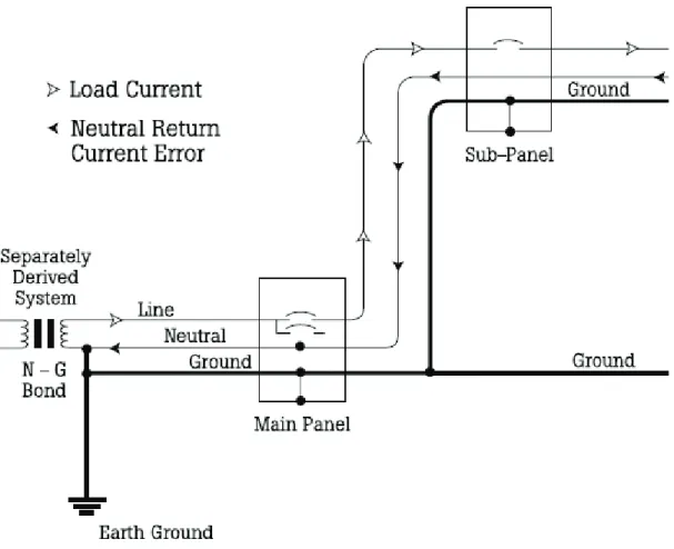
The most common cause of nuisance tripping conditions of electronic trip circuit breaker that contain a ground fault protection function is objectionable neutral-to-ground bonds. The neutral conductor of any separately derived system should only be bonded in a maximum of two places and two places only.
The first allowable and necessary neutral-to-ground bond is located on the Xo terminal of the transformer supplying the service equipment. This specific neutral-to-ground bond is identified as the “system ground” or the “system bond jumper”. The primary function or purpose of the system bonding jumper is to provide for an applicable reference to earth for the system voltage at the origins of the specific and separately derived system to stabilize the voltage. (i.e., 600Y/347V, 480Y/277V, or 208Y/120V, 3 Phase, 4 Wire, Solidly Grounded, “WYE” Systems) The system bonding jumper is employed as a direct connection between the Xo terminal of a supplying transformer, generator, or UPS output terminals and earth. The system bonding jumper is usually connected within the same enclosure as the power supply terminals and the jumper is not normally sized to carry large magnitudes of phase-to-ground fault current.
The second allowable and necessary neutral-to-ground bond is located within the service equipment. This specific neutral-to-ground bonding jumper is called the Main Bonding Jumper
and by definition is the connection between the grounded circuit conductor (neutral) and the equipment grounding conductor at the service. The purpose of the Main Bonding Jumper is to provide a reliable low impedance path for phase-to-ground fault current to return to the power supply source that have been routed to the ground bus in the service equipment.
When objectionable neutral-to-ground bonds are connected downstream of the service equipment a condition can be created where by all of the normal phase imbalanced currents do not flow entirely in the neutral conductors but instead are diverted into the grounding system. Such objectionable neutral-to-ground bonds can cause electronic trip circuit breakers to nuisance trip when there are no actual phase-to ground faults. In addition, the diversion and conduction of neutral currents into the ground plane can cause a great acceleration in the galvanic reaction between dissimilar metals. More importantly, objectionable neutral-to-ground bonds can prevent electronic trip circuit breakers from effectively operating during actual phase-to-ground fault and can cause fires at the point where any and all objectionable neutral-to-ground bonds have been created. See Fig. 1 and Fig. 2 below.
Fig. 1 Proper Neutral-to-Ground Bonds at Supplying Transformer and Service Equipment
Revision 1 10/08 Page 11 of 11
6. Summary
The information provided above by no means covers all of the necessary items and issues to be considered as part of an effective startup program or procedure. However, what has been provided is a listing of some of the most common major issues that Square D Services has encountered during hundreds of start up procedures. It is hoped that the information provided will assist end users or their assigned commissioning agents in any startup program or procedure that is selected for their specific project or facility.
7. References
[1] NFPA 70®, 2008 National Electrical Code®, Quincy, MA: NFPA
[2] NFPA 110, Standard for Emergency and Standby Power Systems, Quincy, MA: NFPA [3] NFPA 111, Standard on Stored Electrical Emergency and Standby Power Systems, Quincy,
MA: NFPA
[4] NPFA 70E®, 2009 Standard for Electrical Safety in the Workplace®, Quincy, MA: NFPA IEEE Std. 81-1983, IEEE Guide for Measuring Earth Resistivity, Ground Impedance, and Earth Surface Potentials of a Ground System