Fitting and operating instructions EN
WS Range: WS355
WS455
WS555
WS655
WS755
BWT WS Range /09-2012 © B WT UK LimitedChanges of technical details are reserved
Important notice: Always keep the fitting and operating instructions close at hand to avoid any mistakes and before carrying out any work on the device, you should read the fitting and operating instructions carefully and follow them. While our data sheets and brochures should provide advice to the best of our knowledge, the content thereof is not legally binding.
BWT WS Range
Water Softener
WS Cover.pdf 1 02/01/2014 13:292
Correct application
This appliance is intended for
domestic use only, and any other use is not supported by the manufacturer and could be dangerous. BWT UK Limited cannot be held liable for damage resulting from the incorrect or improper use of this water softener.
Operation
This appliance can be used by children aged from 8 years and above and persons with reduced physical, sensory or mental capabilities or lack of experience and knowledge if they have been given supervision or instruction concerning use of the appliance in a safe way and understand the hazards involved.
Safety with children
Children must not play with the appliance and any contents therein at anytime.
Extended periods of non-use
If the property is to be left unattended for any length of time e.g. holidays, the water softener should be bypassed/ isolated from the mains water supply by reversing the 3 valve positions as shown in the installation diagram in this manual (see index for details).
After prolonged periods of non-use, ensure inlet and outlet valves are open and bypass valve is closed, and start a manual regeneration as described in Part 2 of this manual.
Protect from high & low temperatures
Important - do not install the water softener where it, or its connections (including the drain overflow lines), will be subject to temperatures under 5ºC or above 40ºC.
Electrical safety
Only use the transformer /plug supplied, before use, ensure that the connection data on the data plate (voltage and frequency) match that of the mains electricity supply. If in any doubt, consult a qualified electrician.
Maintenance
The unit must be isolated from the electricity supply during installation, maintenance and repair work. Your water softener will benefit from regular service -please see welcome pack or call BWT on 01376 334 200 for details.
Cleaning
Please wipe clean with a damp cloth. Do not use solvent based or abrasive cleaning agents as they may cause damage to the high gloss finish.
This water softener complies with all relevant local and national safety requirements. Improper use will invalidate your manufacturers warranty and could lead to injury and material damage.
To help avoid the risk of accidents and unnecessary damage to this unit, please read these instructions carefully before installation and use. Please keep these instructions in a safe place and ensure they are passed on to any future user of the unit.
2
Page
Contents 3
Introduction, features and benefits 4 PART ONE
5 Overview of the softening process
6-7 Installation and operating considerations
8 Installation layout
PART TWO
9-12 Installing your water softener
11 Water hardness test
Programming procedure 12-14 PART THREE Troubleshooting guide 15-17 Specification table 17 Warranty
18
CONTENTS
3
3
Correct application
This appliance is intended for
domestic use only, and any other use is not supported by the manufacturer and could be dangerous. BWT UK Limited cannot be held liable for damage resulting from the incorrect or improper use of this water softener.
Operation
This appliance can be used by children aged from 8 years and above and persons with reduced physical, sensory or mental capabilities or lack of experience and knowledge if they have been given supervision or instruction concerning use of the appliance in a safe way and understand the hazards involved.
Safety with children
Children must not play with the appliance and any contents therein at anytime.
Extended periods of non-use
If the property is to be left unattended for any length of time e.g. holidays, the water softener should be bypassed/ isolated from the mains water supply by reversing the 3 valve positions as shown in the installation diagram in this manual (see index for details).
After prolonged periods of non-use, ensure inlet and outlet valves are open and bypass valve is closed, and start a manual regeneration as described in Part 2 of this manual.
Protect from high & low temperatures
Important - do not install the water softener where it, or its connections (including the drain overflow lines), will be subject to temperatures under 5ºC or above 40ºC.
Electrical safety
Only use the transformer /plug supplied, before use, ensure that the connection data on the data plate (voltage and frequency) match that of the mains electricity supply. If in any doubt, consult a qualified electrician.
Maintenance
The unit must be isolated from the electricity supply during installation, maintenance and repair work. Your water softener will benefit from regular service -please see welcome pack or call BWT on 01376 334 200 for details.
Cleaning
Please wipe clean with a damp cloth. Do not use solvent based or abrasive cleaning agents as they may cause damage to the high gloss finish.
This water softener complies with all relevant local and national safety requirements. Improper use will invalidate your manufacturers warranty and could lead to injury and material damage.
To help avoid the risk of accidents and unnecessary damage to this unit, please read these instructions carefully before installation and use. Please keep these instructions in a safe place and ensure they are passed on to any future user of the unit.
2
Page
Contents 3
Introduction, features and benefits 4 PART ONE
5 Overview of the softening process
6-7 Installation and operating considerations
8 Installation layout
PART TWO
9-12 Installing your water softener
11 Water hardness test
Programming procedure 12-14 PART THREE Troubleshooting guide 15-17 Specification table 17 Warranty
18
CONTENTS
3
4
3
PAR
T ONE
WHAT IS A WATER SOFTENER?
A water softener works by passing hard water through a cylinder containing ion exchange resin.
The resin consists of tiny beads that attract and retain the hardness minerals, allowing the now softened water into your
household water supply.
Resin Brine
Hard water Soft water
Water inlet To drain
Brine pick up Rinse water to drain Hard water SOFTENING CYCLE REGENERATION CYLCE RINSING CYCLE Periodically, these resin beads are
automatically cleaned and regenerated by rinsing with a small amount of brine, (a salt solution).
The brine, with the accumulated hardness is then flushed away to the drain.
All this takes place automatically, all that remains for you to do is occasionally top up the water softener with salt.
3
2
On the following pages we provide full installation and operating instructions. You may find this booklet easier to follow if you first take a few minutes to familiarise yourself with the basic principles of the water softening process and benefits of the "Millennium" valve.
INTRODUCTION
At the heart of your BWT Waterside water softener is the Millennium valve controlled by the BWT “Advanced Memory Electronic Control System” (AMECS). AMECS is
manufactured and tested to meet the latest EU standard for performance, safety and testing of water softeners. The protocol used in the system design is based on the extensive experience of BWT in the UK.
"
Rotary valve means less moving parts for greater reliability."
Flow rates suitable for use on conventional and modern plumbing systems."
Custom backlit easy read display."
At a glance, "capacity remaining indicator" helping to provide a continuous supply of softened water."
Memory back-up facility allows the AMECS to restore all key settings held in its memory after a temporary power supply failure, (for up to 72 hours)."
Low salt alarm."
Low voltage control system."
High capacity resin for generous amounts of softened water between regenerations."
Proportional brining technology reduces water and salt usage for maximum efficiency.FEATURES AND BENEFITS
Thank you for choosing a BWT Waterside water softener.
PART ONE
OVERVIEW OF THE WATER SOFTENING PROCESS
4
On the following pages we provide full installation and operating instructions. You may find this booklet easier to follow if you first take a few minutes to familiarise yourself with the basic principles of the water softening process and benefits of the "Millennium" valve.
INTRODUCTION
At the heart of your BWT WS Range Water Softener is the Millennium valve controlled by the BWT “Advanced Memory Electronic Control System” (AMECS). AMECS is
manufactured and tested to meet the latest EU standard for performance, safety and testing of water softeners. The protocol used in the system design is based on the extensive experience of BWT in the UK.
"
Rotary valve means less moving parts for greater reliability."
Flow rates suitable for use on conventional and modern plumbing systems."
Custom backlit easy read display."
At a glance, "capacity remaining indicator" helping to provide a continuous supply of softened water."
Memory back-up facility allows the AMECS to restore all key settings held in its memory after a temporary power supply failure, (for up to 72 hours)."
Low salt alarm."
Low voltage control system."
High capacity resin for generous amounts of softened water between regenerations."
Proportional brining technology reduces water and salt usage for maximum efficiency.FEATURES AND BENEFITS
5
3
PAR
T ONE
WHAT IS A WATER SOFTENER?
A water softener works by passing hard water through a cylinder containing ion exchange resin.
The resin consists of tiny beads that attract and retain the hardness minerals, allowing the now softened water into your
household water supply.
Resin Brine
Hard water Soft water
Water inlet To drain
Brine pick up Rinse water to drain Hard water SOFTENING CYCLE REGENERATION CYLCE RINSING CYCLE Periodically, these resin beads are
automatically cleaned and regenerated by rinsing with a small amount of brine, (a salt solution).
The brine, with the accumulated hardness is then flushed away to the drain.
All this takes place automatically, all that remains for you to do is occasionally top up the water softener with salt.
3
2
On the following pages we provide full installation and operating instructions. You may find this booklet easier to follow if you first take a few minutes to familiarise yourself with the basic principles of the water softening process and benefits of the "Millennium" valve.
INTRODUCTION
At the heart of your BWT Waterside water softener is the Millennium valve controlled by the BWT “Advanced Memory Electronic Control System” (AMECS). AMECS is
manufactured and tested to meet the latest EU standard for performance, safety and testing of water softeners. The protocol used in the system design is based on the extensive experience of BWT in the UK.
"
Rotary valve means less moving parts for greater reliability."
Flow rates suitable for use on conventional and modern plumbing systems."
Custom backlit easy read display."
At a glance, "capacity remaining indicator" helping to provide a continuous supply of softened water."
Memory back-up facility allows the AMECS to restore all key settings held in its memory after a temporary power supply failure, (for up to 72 hours)."
Low salt alarm."
Low voltage control system."
High capacity resin for generous amounts of softened water between regenerations."
Proportional brining technology reduces water and salt usage for maximum efficiency.FEATURES AND BENEFITS
Thank you for choosing a BWT Waterside water softener.
PART ONE
OVERVIEW OF THE WATER SOFTENING PROCESS
4
On the following pages we provide full installation and operating instructions. You may find this booklet easier to follow if you first take a few minutes to familiarise yourself with the basic principles of the water softening process and benefits of the "Millennium" valve.
INTRODUCTION
At the heart of your BWT WS Range Water Softener is the Millennium valve controlled by the BWT “Advanced Memory Electronic Control System” (AMECS). AMECS is
manufactured and tested to meet the latest EU standard for performance, safety and testing of water softeners. The protocol used in the system design is based on the extensive experience of BWT in the UK.
"
Rotary valve means less moving parts for greater reliability."
Flow rates suitable for use on conventional and modern plumbing systems."
Custom backlit easy read display."
At a glance, "capacity remaining indicator" helping to provide a continuous supply of softened water."
Memory back-up facility allows the AMECS to restore all key settings held in its memory after a temporary power supply failure, (for up to 72 hours)."
Low salt alarm."
Low voltage control system."
High capacity resin for generous amounts of softened water between regenerations."
Proportional brining technology reduces water and salt usage for maximum efficiency.FEATURES AND BENEFITS
6
There are several types of plumbing systems in common use:
1) Static Head – These systems are fitted with storage tanks. The water softener can be installed using the standard 15mm or 22mm installation kit supplied with your water softener.
2) Systems using Combination Boilers (15mm) – For these systems, we recommend that your water softener be “hard plumbed” using copper tube of flexible high flow braided hoses.
Unvented Fully Pressurised Systems (22mm) – As for combination boilers above.
1. Before you begin
The installation of your new water softener is relatively straightforward. However, we would recommend that either a qualified plumber or a person with relevant plumbing experience carries out the installation.
Before embarking on the installation, please ensure you have familiarised yourself with both these instructions and the components required to complete the installation.
2. Positioning the water softener
Please measure your water softener to ensure that it will fit into the area you are placing the unit into. PLEASE remember to include additional space for connecting pipe work in your calculations along with the regular access that is needed for topping the unit up with salt and future service.
Where possible, the distance of both the incoming water supply and nearest drain should be kept to a minimum. Two metres is an ideal distance, however, longer distances are permissible, dependant on the incoming water pressure.
Please remember the weight of your new water softener will considerably increase once installed and filled with salt. Therefore, please ensure your chosen location is strong enough to support an approximate total weight of 50 Kg.
Your new water softener has been designed to operate efficiently and effectively with an incoming water pressure of between 1.7 to 5 BAR. If your water supply is likely to fall outside these limits, then we would recommend that a booster pump or pressure-limiting valve should be fitted respectively.
PLEASE NOTE: UK Water Regulation guidelines on the installation of water softeners indicate that a minimum of one tap
is left as a source of untreated water / drinking water within the home. It is also recommended that any garden taps should also be left untreated.
If the property is to be left unattended for any length of time e.g. holidays, the water softener should be bypassed / isolated from the mains water supply by reversing the 3 valve positions as shown in the installation diagram on page 6. After prolonged periods of non-use, ensure inlet and outlet valves are open and bypass valve is closed and start a manual regeneration as described on page 12.
Important - do not install the water softener where it, or its connections (including the drain overflow lines) will be subject to temperatures under 5ºC or above 40ºC.
INSTALLATION AND
OPERATING CONSIDERATIONS
4
The water softener should be installed within a container with no less than100 litre capacity, to which there should be connected an overflow pipe of no less than 20mm diameter. The overflow should be connected at the bottom of the container and not less than 150mm below the height of any electrical components mounted on the water softener. It is recommended that an anti vacuum valve be fitted to the inlet pipework supplying the water softener.
3. Loft installation
If you are planning to install the water softener above ground level e.g. In the loft, the following instructions should be strictly adhered to.
PAR
T ONE
4. Plumbing systems
5. Backflow prevention device
5
Your water softener installation must include at least one drinking water tap that is not fed by the water softener.
It is recommended that individuals on a low sodium diet should follow the Department of Health's advice that water from a domestic water softener should not be used for drinking or cooking. Softened water contains a small amount of sodium, it has been calculated that 1 pint of softened water contains a similar amount of sodium as two slices of white bread or ¼ pint of milk.
Water that is used for mixing powdered milk for babies must only be taken from an un-softened mains tap as some powdered milks and un-softened water both contain sodium for which young babies have a limited tolerance.
6. Drinking water
PAR
T ONE
INSTALLATION AND
OPERATING CONSIDERATIONS
4
5
When fitted to the supply feeding a single dwelling, a check valve complying with BS6282 Part 1 must be fitted on the cold water feed prior to the installation. All other types of installation require the fitting of a double check valve.
7
There are several types of plumbing systems in common use:
1) Static Head – These systems are fitted with storage tanks. The water softener can be installed using the standard 15mm or 22mm installation kit supplied with your water softener.
2) Systems using Combination Boilers (15mm) – For these systems, we recommend that your water softener be “hard plumbed” using copper tube of flexible high flow braided hoses.
Unvented Fully Pressurised Systems (22mm) – As for combination boilers above.
1. Before you begin
The installation of your new water softener is relatively straightforward. However, we would recommend that either a qualified plumber or a person with relevant plumbing experience carries out the installation.
Before embarking on the installation, please ensure you have familiarised yourself with both these instructions and the components required to complete the installation.
2. Positioning the water softener
Please measure your water softener to ensure that it will fit into the area you are placing the unit into. PLEASE remember to include additional space for connecting pipe work in your calculations along with the regular access that is needed for topping the unit up with salt and future service.
Where possible, the distance of both the incoming water supply and nearest drain should be kept to a minimum. Two metres is an ideal distance, however, longer distances are permissible, dependant on the incoming water pressure.
Please remember the weight of your new water softener will considerably increase once installed and filled with salt. Therefore, please ensure your chosen location is strong enough to support an approximate total weight of 50 Kg.
Your new water softener has been designed to operate efficiently and effectively with an incoming water pressure of between 1.7 to 5 BAR. If your water supply is likely to fall outside these limits, then we would recommend that a booster pump or pressure-limiting valve should be fitted respectively.
PLEASE NOTE: UK Water Regulation guidelines on the installation of water softeners indicate that a minimum of one tap
is left as a source of untreated water / drinking water within the home. It is also recommended that any garden taps should also be left untreated.
If the property is to be left unattended for any length of time e.g. holidays, the water softener should be bypassed / isolated from the mains water supply by reversing the 3 valve positions as shown in the installation diagram on page 6. After prolonged periods of non-use, ensure inlet and outlet valves are open and bypass valve is closed and start a manual regeneration as described on page 12.
Important - do not install the water softener where it, or its connections (including the drain overflow lines) will be subject to temperatures under 5ºC or above 40ºC.
INSTALLATION AND
OPERATING CONSIDERATIONS
4
The water softener should be installed within a container with no less than100 litre capacity, to which there should be connected an overflow pipe of no less than 20mm diameter. The overflow should be connected at the bottom of the container and not less than 150mm below the height of any electrical components mounted on the water softener. It is recommended that an anti vacuum valve be fitted to the inlet pipework supplying the water softener.
3. Loft installation
If you are planning to install the water softener above ground level e.g. In the loft, the following instructions should be strictly adhered to.
PAR
T ONE
4. Plumbing systems
5. Backflow prevention device
5
Your water softener installation must include at least one drinking water tap that is not fed by the water softener.
It is recommended that individuals on a low sodium diet should follow the Department of Health's advice that water from a domestic water softener should not be used for drinking or cooking. Softened water contains a small amount of sodium, it has been calculated that 1 pint of softened water contains a similar amount of sodium as two slices of white bread or ¼ pint of milk.
Water that is used for mixing powdered milk for babies must only be taken from an un-softened mains tap as some powdered milks and un-softened water both contain sodium for which young babies have a limited tolerance.
6. Drinking water
PAR
T ONE
INSTALLATION AND
OPERATING CONSIDERATIONS
4
5
When fitted to the supply feeding a single dwelling, a check valve complying with BS6282 Part 1 must be fitted on the cold water feed prior to the installation. All other types of installation require the fitting of a double check valve.
8
It is very important to establish the water pressure before installing the water softener. If the water pressure is low, then the water softener may not operate effectively. If it is too high, then components inside the unit may be damaged.
Water pressure should be tested with a gauge at the kitchen tap or outside tap. It should be noted that water pressure can increase at periods of low water usage e.g. overnight. If, therefore, the daytime pressure exceeds 5 BAR or if you are unsure about pressure, then a pressure-limiting valve should be fitted.
Where the pressure is less than 1.7 BAR, a booster pump may be required.
7
PART TWO
INSTALLING YOUR WATER SOFTENER
2. Inlet and outlet connections 1. Positioning the water softener
With the bypass valve open and the inlet / outlet valves closed, the unit can be connected to the plumbing system. Arrows on the inlet and outlet piping from the valve will confirm the direction of flow.
Connections can be made with either conventional copper tube and fittings or the flexible hoses supplied, ensure hoses are not kinked as this may restrict flow.
3. Drain connection
Push the flexible drain hose onto the barbed connector (Drain) as shown on page 6 and secure with the clip provided. Run the drain hose to a stand pipe or to a drain. The air gap needs to be at least 20mm . Softened water will have no adverse effect on a septic tank. You can extend the drain up to 9m if you have sufficient pressure (greater than 3 BAR). The drain hose must not be kinked or restricted in any way as this will cause an overflow from the brine cabinet.
Frost protection
o
If the drain hose or connecting pipework is likely to be subject to temperatures below 0 C, it must be protected to prevent freezing. Failure to observe this precaution could lead to the water softener overflowing.
Raising the drain hose
If you have a water pressure of 3 BAR or more, you can raise the drain to a maximum of 3 metres above the valve head.
PAR
T TWO
Outlet from
softener Inlet tosoftener
Outlet valve
shown open Inlet valveshown open
By-pass valve shown closed Inlet from mains Non-return valve To rising main
Use reducing bush for 15mm pipework
*
*
*
*
Key to the diagram A. Non return valve
B. Pressure reducing valve (where required) C. Inlet valve D. By-pass valve E. Outlet valve
6
PAR
T ONE
A B C E DMains stop valve
Drinking water Drain hose Overflow* Valve Head Brine Cabinet Inlet Outlet Rising Main
* The overflow must discharge to a place that is visible outside the building.
TYPICAL INSTALLATION LAYOUT
It is very important to establish the water pressure before installing the water softener. If the water pressure is low, then the water softener may not operate effectively. If it is too high, then components inside the unit may be damaged.
Water pressure should be tested with a gauge at the kitchen tap or outside tap. It should be noted that water pressure can increase at periods of low water usage e.g. overnight. If, therefore, the daytime pressure exceeds 5 BAR or if you are unsure about pressure, then a pressure-limiting valve should be fitted.
Where the pressure is less than 1.7 BAR, a booster pump may be required.
7
PART TWO
INSTALLING YOUR WATER SOFTENER
2. Inlet and outlet connections 1. Positioning the water softener
With the bypass valve open and the inlet / outlet valves closed, the unit can be connected to the plumbing system. Arrows on the inlet and outlet piping from the valve will confirm the direction of flow.
Connections can be made with either conventional copper tube and fittings or the flexible hoses supplied, ensure hoses are not kinked as this may restrict flow.
3. Drain connection
Push the flexible drain hose onto the barbed connector (Drain) as shown on page 6 and secure with the clip provided. Run the drain hose to a stand pipe or to a drain. The air gap needs to be at least 20mm . Softened water will have no adverse effect on a septic tank. You can extend the drain up to 9m if you have sufficient pressure (greater than 3 BAR). The drain hose must not be kinked or restricted in any way as this will cause an overflow from the brine cabinet.
Frost protection
o
If the drain hose or connecting pipework is likely to be subject to temperatures below 0 C, it must be protected to prevent freezing. Failure to observe this precaution could lead to the water softener overflowing.
Raising the drain hose
If you have a water pressure of 3 BAR or more, you can raise the drain to a maximum of 3 metres above the valve head.
PAR
T TWO
Outlet from
softener Inlet tosoftener
Outlet valve
shown open Inlet valveshown open
By-pass valve shown closed Inlet from mains Non-return valve To rising main
Use reducing bush for 15mm pipework
*
*
*
*
Key to the diagram A. Non return valve
B. Pressure reducing valve (where required) C. Inlet valve D. By-pass valve E. Outlet valve
6
PAR
T ONE
A B C E DMains stop valve
Drinking water Drain hose Overflow* Valve Head Brine Cabinet Inlet Outlet Rising Main
* The overflow must discharge to a place that is visible outside the building.
9
It is very important to establish the water pressure before installing the water softener. If the water pressure is low, then the water softener may not operate effectively. If it is too high, then components inside the unit may be damaged.
Water pressure should be tested with a gauge at the kitchen tap or outside tap. It should be noted that water pressure can increase at periods of low water usage e.g. overnight. If, therefore, the daytime pressure exceeds 5 BAR or if you are unsure about pressure, then a pressure-limiting valve should be fitted.
Where the pressure is less than 1.7 BAR, a booster pump may be required.
7
PART TWO
INSTALLING YOUR WATER SOFTENER
2. Inlet and outlet connections 1. Positioning the water softener
With the bypass valve open and the inlet / outlet valves closed, the unit can be connected to the plumbing system. Arrows on the inlet and outlet piping from the valve will confirm the direction of flow.
Connections can be made with either conventional copper tube and fittings or the flexible hoses supplied, ensure hoses are not kinked as this may restrict flow.
3. Drain connection
Push the flexible drain hose onto the barbed connector (Drain) as shown on page 6 and secure with the clip provided. Run the drain hose to a stand pipe or to a drain. The air gap needs to be at least 20mm . Softened water will have no adverse effect on a septic tank. You can extend the drain up to 9m if you have sufficient pressure (greater than 3 BAR). The drain hose must not be kinked or restricted in any way as this will cause an overflow from the brine cabinet.
Frost protection
o
If the drain hose or connecting pipework is likely to be subject to temperatures below 0 C, it must be protected to prevent freezing. Failure to observe this precaution could lead to the water softener overflowing.
Raising the drain hose
If you have a water pressure of 3 BAR or more, you can raise the drain to a maximum of 3 metres above the valve head.
PAR
T TWO
Outlet from
softener Inlet tosoftener
Outlet valve
shown open Inlet valveshown open
By-pass valve shown closed Inlet from mains Non-return valve To rising main
Use reducing bush for 15mm pipework
*
*
*
*
Key to the diagram A. Non return valve
B. Pressure reducing valve (where required) C. Inlet valve D. By-pass valve E. Outlet valve
6
PAR
T ONE
A B C E DMains stop valve
Drinking water Drain hose Overflow* Valve Head Brine Cabinet Inlet Outlet Rising Main
* The overflow must discharge to a place that is visible outside the building.
TYPICAL INSTALLATION LAYOUT
It is very important to establish the water pressure before installing the water softener. If the water pressure is low, then the water softener may not operate effectively. If it is too high, then components inside the unit may be damaged.
Water pressure should be tested with a gauge at the kitchen tap or outside tap. It should be noted that water pressure can increase at periods of low water usage e.g. overnight. If, therefore, the daytime pressure exceeds 5 BAR or if you are unsure about pressure, then a pressure-limiting valve should be fitted.
Where the pressure is less than 1.7 BAR, a booster pump may be required.
7
PART TWO
INSTALLING YOUR WATER SOFTENER
2. Inlet and outlet connections 1. Positioning the water softener
With the bypass valve open and the inlet / outlet valves closed, the unit can be connected to the plumbing system. Arrows on the inlet and outlet piping from the valve will confirm the direction of flow.
Connections can be made with either conventional copper tube and fittings or the flexible hoses supplied, ensure hoses are not kinked as this may restrict flow.
3. Drain connection
Push the flexible drain hose onto the barbed connector (Drain) as shown on page 6 and secure with the clip provided. Run the drain hose to a stand pipe or to a drain. The air gap needs to be at least 20mm . Softened water will have no adverse effect on a septic tank. You can extend the drain up to 9m if you have sufficient pressure (greater than 3 BAR). The drain hose must not be kinked or restricted in any way as this will cause an overflow from the brine cabinet.
Frost protection
o
If the drain hose or connecting pipework is likely to be subject to temperatures below 0 C, it must be protected to prevent freezing. Failure to observe this precaution could lead to the water softener overflowing.
Raising the drain hose
If you have a water pressure of 3 BAR or more, you can raise the drain to a maximum of 3 metres above the valve head.
PAR
T TWO
Outlet from
softener Inlet tosoftener
Outlet valve
shown open Inlet valveshown open
By-pass valve shown closed Inlet from mains Non-return valve To rising main
Use reducing bush for 15mm pipework
*
*
*
*
Key to the diagram A. Non return valve
B. Pressure reducing valve (where required) C. Inlet valve D. By-pass valve E. Outlet valve
6
PAR
T ONE
A B C E DMains stop valve
Drinking water Drain hose Overflow* Valve Head Brine Cabinet Inlet Outlet Rising Main
* The overflow must discharge to a place that is visible outside the building.
10
Now place the water softener salt in the brine cabinet. Use care cubes (tablet salt) only, this is available from your local BWT stockist.
0:00
Lift off this cover and connect the jack plug of the power lead to the
control box behind the front panel Rigid plastic 3/4" overflow pipe (not supplied with the softener) should be connected to
the push fit elbow at the rear of the cabinet (see page 6). Run the pipe downhill to the outside of the building. Take care that the overflow does not discharge where damage could occur.
If the water softener is fitted in a cellar or basement, the overflow can be run to a storage tank. Do not elevate the overflow hose. Do not use jointing cement on the fitting.
4. Overflow connections
5. Electrical connections
For added safety, peace of mind and ease of installation, your water softener is powered by low voltage via a plug in transformer. This transformer must be connected to a switched socket. Plug the transformer into the socket with the switch in the OFF position.
8
7. Blending control
6. Filling the brine cabinet, salt usage and salt alarm
All machines are factory set to produce water that is soft. If you prefer water which is less soft, turn the blending knob on the left side of the valve anti-clockwise until the water meets your requirements.
Notes on salt usage
Your water softener will only perform effectively if there is salt in the brine cabinet during the regeneration process. It is therefore essential that the salt level does not fall lower than 150mm in depth when measured from the base of the brine cabinet.
N.B. The softener requires no priming, add no water to the brine tank. During regeneration, salt will not enter your water system as the salt used in the regeneration process is rinsed safely away to drain.
Your water softener is equipped with a low salt reminder, this monitors your water usage and sounds an audible alarm whilst displaying the word “SALt”, as a reminder to check the salt level. To reset the salt alarm, fill the brine tank with salt and press the key twice.
PAR
T
TWO
9. Switching on for the first time
" Check that the inlet / outlet hoses or couplings are properly connected i.e. inlet-to-inlet,
outlet-to-outlet.
" The by-pass arrangement should be in the open position i.e. the inlet and outlet valves
closed, by-pass valve open. Mains stop valve open.
" Check that the Brine Cabinet contains salt.
" Check that the water softener is connected to the drain and the overflow pipe is
connected. The drain and overflow must not be linked to each other.
8. Testing for the water hardness in your area
Water hardness can vary from one location to another. To determine the hardness of the water feeding your water softener (un-softened supply), use the hardness test kit supplied.
" Fill the test bottle .
" Add the tablets to the solution one tablet at a time.
" Shake the bottle in between and keep adding tablets to the water until the solution turns
from wine red to blue, record the number of tablets as you go.
" Using the data table supplied with your kit, match up the number of tablets with the
hardness. You will need this figure when programming your water softener in the next section of this manual.
supplied to the fill line with water from a hard water tap
9
PAR
T TWO
" Gently open the inlet valve so that water flows into the resin vessel.
" Switch on the power, you will hear the valve move quietly into the start position. When
the positioning process has been completed (which can take up to 10 minutes), you will hear the movement stop. The valve has now reached its start position in preparation for the programming procedure.
" Close the by-pass valve. " Gently open the outlet valve.
" Check for leaks, take corrective action to stop leaks if required.
" Your water softener is now on line and you may start the valve programming procedure
set out in the next section of this manual. Now place the water softener salt in the brine cabinet. Use care cubes (tablet salt)
only, this is available from your local BWT stockist.
0:00
Lift off this cover and connect the jack plug of the power lead to the
control box behind the front panel Rigid plastic 3/4" overflow pipe (not supplied with the softener) should be connected to
the push fit elbow at the rear of the cabinet (see page 6). Run the pipe downhill to the outside of the building. Take care that the overflow does not discharge where damage could occur.
If the water softener is fitted in a cellar or basement, the overflow can be run to a storage tank. Do not elevate the overflow hose. Do not use jointing cement on the fitting.
4. Overflow connections
5. Electrical connections
For added safety, peace of mind and ease of installation, your water softener is powered by low voltage via a plug in transformer. This transformer must be connected to a switched socket. Plug the transformer into the socket with the switch in the OFF position.
8
7. Blending control
6. Filling the brine cabinet, salt usage and salt alarm
All machines are factory set to produce water that is soft. If you prefer water which is less soft, turn the blending knob on the left side of the valve anti-clockwise until the water meets your requirements.
Notes on salt usage
Your water softener will only perform effectively if there is salt in the brine cabinet during the regeneration process. It is therefore essential that the salt level does not fall lower than 150mm in depth when measured from the base of the brine cabinet.
N.B. The softener requires no priming, add no water to the brine tank. During regeneration, salt will not enter your water system as the salt used in the regeneration process is rinsed safely away to drain.
Your water softener is equipped with a low salt reminder, this monitors your water usage and sounds an audible alarm whilst displaying the word “SALt”, as a reminder to check the salt level. To reset the salt alarm, fill the brine tank with salt and press the key twice.
PAR
T
TWO
9. Switching on for the first time
" Check that the inlet / outlet hoses or couplings are properly connected i.e. inlet-to-inlet,
outlet-to-outlet.
" The by-pass arrangement should be in the open position i.e. the inlet and outlet valves
closed, by-pass valve open. Mains stop valve open.
" Check that the Brine Cabinet contains salt.
" Check that the water softener is connected to the drain and the overflow pipe is
connected. The drain and overflow must not be linked to each other.
8. Testing for the water hardness in your area
Water hardness can vary from one location to another. To determine the hardness of the water feeding your water softener (un-softened supply), use the hardness test kit supplied.
" Fill the test bottle .
" Add the tablets to the solution one tablet at a time.
" Shake the bottle in between and keep adding tablets to the water until the solution turns
from wine red to blue, record the number of tablets as you go.
" Using the data table supplied with your kit, match up the number of tablets with the
hardness. You will need this figure when programming your water softener in the next section of this manual.
supplied to the fill line with water from a hard water tap
9
PAR
T TWO
" Gently open the inlet valve so that water flows into the resin vessel.
" Switch on the power, you will hear the valve move quietly into the start position. When
the positioning process has been completed (which can take up to 10 minutes), you will hear the movement stop. The valve has now reached its start position in preparation for the programming procedure.
" Close the by-pass valve. " Gently open the outlet valve.
" Check for leaks, take corrective action to stop leaks if required.
" Your water softener is now on line and you may start the valve programming procedure
11
Now place the water softener salt in the brine cabinet. Use care cubes (tablet salt)only, this is available from your local BWT stockist.
0:00
Lift off this cover and connect the jack plug of the power lead to the
control box behind the front panel Rigid plastic 3/4" overflow pipe (not supplied with the softener) should be connected to
the push fit elbow at the rear of the cabinet (see page 6). Run the pipe downhill to the outside of the building. Take care that the overflow does not discharge where damage could occur.
If the water softener is fitted in a cellar or basement, the overflow can be run to a storage tank. Do not elevate the overflow hose. Do not use jointing cement on the fitting.
4. Overflow connections
5. Electrical connections
For added safety, peace of mind and ease of installation, your water softener is powered by low voltage via a plug in transformer. This transformer must be connected to a switched socket. Plug the transformer into the socket with the switch in the OFF position.
8
7. Blending control
6. Filling the brine cabinet, salt usage and salt alarm
All machines are factory set to produce water that is soft. If you prefer water which is less soft, turn the blending knob on the left side of the valve anti-clockwise until the water meets your requirements.
Notes on salt usage
Your water softener will only perform effectively if there is salt in the brine cabinet during the regeneration process. It is therefore essential that the salt level does not fall lower than 150mm in depth when measured from the base of the brine cabinet.
N.B. The softener requires no priming, add no water to the brine tank. During regeneration, salt will not enter your water system as the salt used in the regeneration process is rinsed safely away to drain.
Your water softener is equipped with a low salt reminder, this monitors your water usage and sounds an audible alarm whilst displaying the word “SALt”, as a reminder to check the salt level. To reset the salt alarm, fill the brine tank with salt and press the key twice.
PAR
T
TWO
9. Switching on for the first time
" Check that the inlet / outlet hoses or couplings are properly connected i.e. inlet-to-inlet,
outlet-to-outlet.
" The by-pass arrangement should be in the open position i.e. the inlet and outlet valves
closed, by-pass valve open. Mains stop valve open.
" Check that the Brine Cabinet contains salt.
" Check that the water softener is connected to the drain and the overflow pipe is
connected. The drain and overflow must not be linked to each other.
8. Testing for the water hardness in your area
Water hardness can vary from one location to another. To determine the hardness of the water feeding your water softener (un-softened supply), use the hardness test kit supplied.
" Fill the test bottle .
" Add the tablets to the solution one tablet at a time.
" Shake the bottle in between and keep adding tablets to the water until the solution turns
from wine red to blue, record the number of tablets as you go.
" Using the data table supplied with your kit, match up the number of tablets with the
hardness. You will need this figure when programming your water softener in the next section of this manual.
supplied to the fill line with water from a hard water tap
9
PAR
T TWO
" Gently open the inlet valve so that water flows into the resin vessel.
" Switch on the power, you will hear the valve move quietly into the start position. When
the positioning process has been completed (which can take up to 10 minutes), you will hear the movement stop. The valve has now reached its start position in preparation for the programming procedure.
" Close the by-pass valve. " Gently open the outlet valve.
" Check for leaks, take corrective action to stop leaks if required.
" Your water softener is now on line and you may start the valve programming procedure
set out in the next section of this manual. Now place the water softener salt in the brine cabinet. Use care cubes (tablet salt)
only, this is available from your local BWT stockist.
0:00
Lift off this cover and connect the jack plug of the power lead to the
control box behind the front panel Rigid plastic 3/4" overflow pipe (not supplied with the softener) should be connected to
the push fit elbow at the rear of the cabinet (see page 6). Run the pipe downhill to the outside of the building. Take care that the overflow does not discharge where damage could occur.
If the water softener is fitted in a cellar or basement, the overflow can be run to a storage tank. Do not elevate the overflow hose. Do not use jointing cement on the fitting.
4. Overflow connections
5. Electrical connections
For added safety, peace of mind and ease of installation, your water softener is powered by low voltage via a plug in transformer. This transformer must be connected to a switched socket. Plug the transformer into the socket with the switch in the OFF position.
8
7. Blending control
6. Filling the brine cabinet, salt usage and salt alarm
All machines are factory set to produce water that is soft. If you prefer water which is less soft, turn the blending knob on the left side of the valve anti-clockwise until the water meets your requirements. Notes on salt usage
Your water softener will only perform effectively if there is salt in the brine cabinet during the regeneration process. It is therefore essential that the salt level does not fall lower than 150mm in depth when measured from the base of the brine cabinet.
N.B. The softener requires no priming, add no water to the brine tank. During regeneration, salt will not enter your water system as the salt used in the regeneration process is rinsed safely away to drain.
Your water softener is equipped with a low salt reminder, this monitors your water usage and sounds an audible alarm whilst displaying the word “SALt”, as a reminder to check the salt level. To reset the salt alarm, fill the brine tank with salt and press the key twice.
PAR
T
TWO
9. Switching on for the first time
" Check that the inlet / outlet hoses or couplings are properly connected i.e. inlet-to-inlet,
outlet-to-outlet.
" The by-pass arrangement should be in the open position i.e. the inlet and outlet valves
closed, by-pass valve open. Mains stop valve open.
" Check that the Brine Cabinet contains salt.
" Check that the water softener is connected to the drain and the overflow pipe is
connected. The drain and overflow must not be linked to each other.
8. Testing for the water hardness in your area
Water hardness can vary from one location to another. To determine the hardness of the water feeding your water softener (un-softened supply), use the hardness test kit supplied.
" Fill the test bottle .
" Add the tablets to the solution one tablet at a time.
" Shake the bottle in between and keep adding tablets to the water until the solution turns
from wine red to blue, record the number of tablets as you go.
" Using the data table supplied with your kit, match up the number of tablets with the
hardness. You will need this figure when programming your water softener in the next section of this manual.
supplied to the fill line with water from a hard water tap
9
PAR
T TWO
" Gently open the inlet valve so that water flows into the resin vessel.
" Switch on the power, you will hear the valve move quietly into the start position. When
the positioning process has been completed (which can take up to 10 minutes), you will hear the movement stop. The valve has now reached its start position in preparation for the programming procedure.
" Close the by-pass valve. " Gently open the outlet valve.
" Check for leaks, take corrective action to stop leaks if required.
" Your water softener is now on line and you may start the valve programming procedure
12
5. Charge Bar
Having set the display on the control facia, you will notice that during normal operation, there is a charge bar running along the bottom of the display. This charge bar shows the percentage of water softener capacity remaining since the last regeneration. Immediately following a regeneration, the charge bar returns to 100%.
Set
00:00
Time
6. Resetting the display during normal operation.
If the time is to be adjusted during normal operation, press any key to illuminate the display, press the
keys will alter the time as described on page10.
key once. The display will flash and indicate present time. Using the
7. Power loss
The AMECS system will maintain the individual programming parameters of the water softener for up to 72 hours.
If the power cut lasts longer than 72 hours, the control will flash "00:00" when power is returned to the control.The unit will continue to keep time from the moment power is restored. In this situation, the time of day willneed to be reset.
10
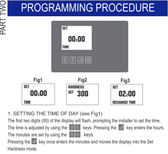
1. SETTING THE TIME OF DAY (see Fig1)
The first two digits (00) of the display will flash, prompting the installer to set the time. The time is adjusted by using the keys. Pressing the key enters the hours. The minutes are set by using the
keys
Pressing the
key once enters the minutes and moves the display into the Set Hardness mode. . Set
00:00
TimePAR
T THREE
2. SETTING THE WATER HARDNESS (see Fig2)
The display default is 300 (typical hardness level) which indicates a setting suitable for hard water with a value of 300 parts per million of hardness minerals. Use the
keys to adjust the setting to match that of the one you obtained / identified earlier. See page 9 for details.
Pressing the set key once enters the hardness and moves the display to Set Recharge Time Mode.
Hardness Set
300
PROGRAMMING PROCEDURE
PAR
T
TWO
Set02:00
RECHARGE TimeFig1
Fig2
Fig3
3. SETTING THE RECHARGE TIME (see Fig3)
To operate effectively, your water softener needs to regenerate periodically (dependent on the hardness of the supply and amount of water used). The default time of day when this is to occur is 2.00am. To alter this setting, use the keys.
Pressing the key once enters the recharge time and returns the display to Normal Operation Mode and no further adjustment of the water softener is required.
8. Flow indicator
During normal operation, a flow indicator will flash on the display at a rate of one litre per pulse when water is passing through the softener.
9. Cleaning
Your water softener may be cleaned using a damp cloth and a mild detergent. Do not use bleaches, solvents or spirits as they may damage the surfaces.
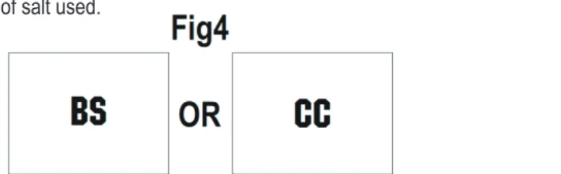
4. Setting The Type Of Salt Used. (WS455 & WS555 only) See Fig 4.
To operate effectively, your water softener must be set to the type of salt that you intend to use in the system. Block salt (BS) and care cubes (CC) are suitable. Use the keys to select the type of salt used.
Pressing the button will return the display to the Normal Operation mode. Programming is now complete and now further adjustments of the water softener is required.
Remember to check the salt and water level in the brine cabinet weekly.
11
5. Charge Bar
Having set the display on the control facia, you will notice that during normal operation, there is a charge bar running along the bottom of the display. This charge bar shows the percentage of water softener capacity remaining since the last regeneration. Immediately following a regeneration, the charge bar returns to 100%.
Set
00:00
Time
6. Resetting the display during normal operation.
If the time is to be adjusted during normal operation, press any key to illuminate the display, press the
keys will alter the time as described on page10.
key once. The display will flash and indicate present time. Using the
7. Power loss
The AMECS system will maintain the individual programming parameters of the water softener for up to 72 hours.
If the power cut lasts longer than 72 hours, the control will flash "00:00" when power is returned to the control.The unit will continue to keep time from the moment power is restored. In this situation, the time of day willneed to be reset.
10
1. SETTING THE TIME OF DAY (see Fig1)
The first two digits (00) of the display will flash, prompting the installer to set the time. The time is adjusted by using the keys. Pressing the key enters the hours. The minutes are set by using the
keys
Pressing the
key once enters the minutes and moves the display into the Set Hardness mode. . Set
00:00
TimePAR
T THREE
2. SETTING THE WATER HARDNESS (see Fig2)
The display default is 300 (typical hardness level) which indicates a setting suitable for hard water with a value of 300 parts per million of hardness minerals. Use the
keys to adjust the setting to match that of the one you obtained / identified earlier. See page 9 for details.
Pressing the set key once enters the hardness and moves the display to Set Recharge Time Mode.
Hardness Set
300
PROGRAMMING PROCEDURE
PAR
T
TWO
Set02:00
RECHARGE TimeFig1
Fig2
Fig3
3. SETTING THE RECHARGE TIME (see Fig3)
To operate effectively, your water softener needs to regenerate periodically (dependent on the hardness of the supply and amount of water used). The default time of day when this is to occur is 2.00am. To alter this setting, use the keys.
Pressing the key once enters the recharge time and returns the display to Normal Operation Mode and no further adjustment of the water softener is required.
8. Flow indicator
During normal operation, a flow indicator will flash on the display at a rate of one litre per pulse when water is passing through the softener.
9. Cleaning
Your water softener may be cleaned using a damp cloth and a mild detergent. Do not use bleaches, solvents or spirits as they may damage the surfaces.
4. Setting The Type Of Salt Used. (WS455 & WS555 only) See Fig 4.
To operate effectively, your water softener must be set to the type of salt that you intend to use in the system. Block salt (BS) and care cubes (CC) are suitable. Use the keys to select the type of salt used.
Pressing the button will return the display to the Normal Operation mode. Programming is now complete and now further adjustments of the water softener is required.
Remember to check the salt and water level in the brine cabinet weekly.