Electric Heat Tracing
Electric Heat Tracing
Notes . . .
1. Refer to the heating cable product specifi cation sheets for temperature ratings as limited by the manufacturer. 2. For foundation heating with RSX, refer to Form TEP0059.
3. For foundation heating with FP, refer to Form TEP0079.
Complete Electric Heat Tracing System . . .
Types of Heating Cables
1. . .
Self-Regulating Heating Cables:
BSX™ (refer to Form TEP0067U)
1725 II 2 G & D Ex e II T5 or T6 DEMKO 02ATEX0132424, UL 06.0013 Ex e II T5 or T6
RSX™ 15 (refer to Form TEP0048U)2
1725 II 2 G Ex e II T4 to T6 KEMA 07ATEX0179, KEMA 07.0052 Ex e II T4 to T6
HTSX™ (refer to Form TEP0074U)
1725 II 2 G Ex eb IIC T2 or T3, II 2 D Ex tb IIIC T300°C or T200°C FM 12ATEX0014 FMG 12.0003 Ex eb IIC T2 or T3, Ex tb IIIC T300°C or T200°C
KSX™ (refer to Form TEP0072U)
1725 II 2 G Ex e II T3 to T6, II 2 D Ex tD A21 IP66/IP67 T200°C to T85°C FM 07ATEX0027 FMG 06.0009 Ex e II T3 to T6,
Ex tD A21 IP66/IP67 T200°C to T85°C
VSX™ (refer to Form TEP0008U)
1725 II 2 G & D Ex e II T3 DEMKO 02ATEX0152667 UL 05.0008x Ex e II T3
Power-Limiting Heating Cable:
HPT™ (refer to Form TEP0011U)
1725 II 2 G Ex e II T2 to T6, II 2 D Ex tD A21 T300°C to T85°C FM 07ATEX0028 FMG 06.0006 Ex e II T2 to T6
Parallel Constant Watt Heating Cable:
FP (refer to Form TEP0016U)3
1725 II 2 G Ex e II T3 to T6, II 2 D Ex tD A21 IP66/IP67 T200°C to T85°C FM 07ATEX0016 FMG 06.0008 Ex e II T3 to T6,
Ex tD A21 IP66/IP67 T200°C to T85°C
Series Constant Watt Heating Cables:
HTEK™ (refer to Form TEP0022U)
1725 II 2 G Ex eb IIC T260°C (T2) to T6, II 2 D Ex tb IIIC T260°C to T85°C FM 11ATEX0050 CCVE 11.0002 Ex eb IIC T260°C (T2) to T6, Ex tb IIIC T260°C to T85°C
TEK™ (refer to Form TEP0021U)
1725 II 2 G Ex eb IIC T260°C (T2) to T6, II 2 D Ex tb IIIC T260°C to T85°C FM 11ATEX0050 CCVE 11.0002 Ex eb IIC T260°C (T2) to T6, Ex tb IIIC T260°C to T85°C
TESH™ (refer to Form TEP0070U)
Electric Heat Tracing
Site Practice . . .
1. Provide protective clothing, and other protective equipment needed to isolate employees from potential arc fl ash and shock hazards identifi ed in the analysis. 2. Provide training to employees for understanding the purpose/function of the electrical heat tracing and the electrical power supply/control equipment. In addition, how to recognize and avoid the hazards associated with operation and maintenance.
3. Apply safe work practices including the following:
• Identify the circuit or equipment to be de-energized and all possible sources of electrical energy supplies to the specfi c circuit or equipment.
• Disconnect both legs of the power supply cable at the circuit breakers, disconnect switches, and any other applicable points.
• Apply lockout/tagout devices according to established procedures.
• Visually verify that the circuit disconnect devices are open prior to connecting power cable to heat tracers. • Test for absence of voltage with an approved voltmeter
(where the voltmeter is tested on a known circuit voltage prior to and immediately following application).
• For protection against accidental energizing of supply conductors, apply temporary jumpers rated for the available fault duty between each supply conductor and earth/ground.
Illustration A: Typical Heat Tracing Installation
Notes . . .
1. Refer to Page 1 for cable types and approval.
2. Illustration depicts a typical self-regulating heating circuit.
3. Temperature control is recommended for all freeze protection and temperature maintenance heat tracing applications.
4. All heat-traced lines must be thermally insulated.
5. Refer to Thermon form number PN50273U for installation instructions for MI heating cable.
The following installation procedures are for the installation of a Thermon electric heat tracing system1. The installation must comply with Thermon requirements and be installed in accordance wit the regulations as per standard EN-IEC 60079-14 and EN-IEC 60079-30-2 for hazardous areas (where applicable), and any other applicable national and local electric codes.
Individuals installing these products are responsible for complying with all applicable safety and health guidelines. Proper personal protective equipment, or PPE, should be utilized during installation. Contact Thermon if you have any additional questions.
Applications . . .
1. Electric heat tracing cables are used for freeze protection or temperature maintenance of piping, tanks and instrumentation. This set of instructions covers typical piping applications. For installation details on tanks and instrumentation, refer to the Installation Guides on our website www.thermon.com.
2. Heat tracing cables may be installed in ordinary (nonclassifi ed) and hazardous (classifi ed) locations depending on the specifi c cable options and approvals1.
8 5 4 6 5a 1 2 3 7
Complete Electric Heat Tracing System . . .
A complete electric heat tracing system may typically include the following components2:
1. Electric heat tracing cable1, 5 (self-regulating, power-limiting, parallel constant watt or series constant watt). 2. Power connection kit.
3. RTD sensor or control thermostat3.
4. In-line/T-splice kit (permits two or three cables to be spliced together).
5. Cable end termination. 5a. End of circuit light kit.
6. Attachment tape (use on 30cm intervals or as required by code or specifi cation).
7. “Electric Heat Tracing” label (peel-and-stick label attaches to insulation vapor barrier on 3m intervals or as required by code or specifi cation).
8. Thermal insulation4 and vapor barrier (by others). The absence of any of these items can cause a system to malfunction or represent a safety hazard.
Electric Heat Tracing
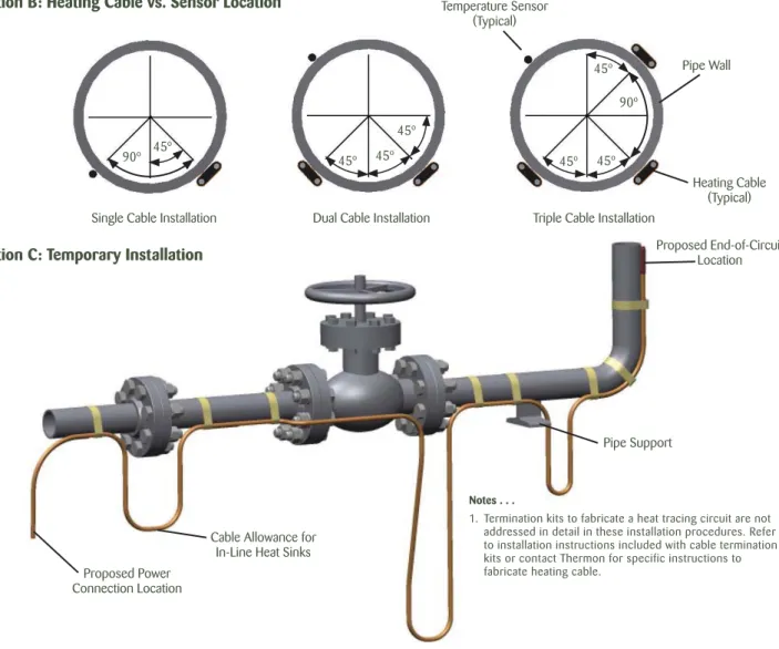
Proposed Power Connection Location
Cable Allowance for In-Line Heat Sinks
Pipe Support
Proposed End-of-Circuit Location
Illustration C: Temporary Installation
Notes . . .
1. Termination kits to fabricate a heat tracing circuit are not addressed in detail in these installation procedures. Refer to installation instructions included with cable termination kits or contact Thermon for specific instructions to fabricate heating cable.
Before Installing Cable . . .
1. Be sure all piping and equipment to be traced is completely installed and pressure tested.
2. Surface areas where heat tracing is to be installed must be reasonably clean. Remove dirt, rust and scale with a wire brush and oil and grease fi lms with a suitable solvent.
Initial Installation . . .
1. Locate the cable on the lower quadrant of the pipe at the 4 or 8 o’clock position. If accessibility is a problem the cable may be installed at the 10 or 2 o’clock position. Temperature sensor should be located at least 90° from all heating cables. Refer to Illustration B for Heating Cable vs. Sensor Location.
2. Begin temporary installation at the proposed end-of-circuit location and lay out heating end-of-circuit on the pipe, allowing extra cable for the power connection and for any splice locations1. Refer to Illustration C for temporary installation.
3. Make heating cable allowances for valves, fl anges, elbows and supports as per the applicable drawings and table on pages 5 and 6 of these installation procedures.
Upon Receiving Cable . . .
1. Upon receiving heating cable, check to make sure the proper type and output have been received. All fl exible cables have the catalog number, voltage rating and watt output printed on the jacket.
2. Visually inspect cable for any damage incurred during shipment.
The heating cable should be tested to ensure electrical integrity with at least a 500 Vdc megger
between the heating cable bus wires and the heating cable metallic braid. IEEE 515 and EN-IEC 60079-30 recommend that the test voltage for polymer insulated heating cables be 2500 Vdc. Minimum resistance should be 20 megohms. Connect the positive lead of the megger to the cable bus wires and the negative lead to the metallic braid.
(Record 1 on Insulation Resistance Test Page 9 and 10)
3. Store in dry location.
Single Cable Installation Dual Cable Installation Triple Cable Installation
Heating Cable (Typical) Pipe Wall Temperature Sensor (Typical) 45º 45º 45º 45º 45º 90º
Illustration B: Heating Cable vs. Sensor Location
45º
45º 90º
Electric Heat Tracing
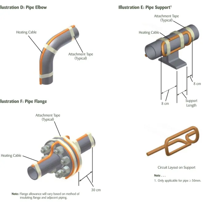
Circuit Layout on Support
Illustration D: Pipe Elbow
Heating Cable
Illustration E: Pipe Support1
Illustration F: Pipe Flange
Attachment Tape (Typical) Support Length Attachment Tape (Typical) Heating Cable 8 cm 8 cm
4. Flanges: Allow cable to be looped around pipe on each side of and adjacent to the fl ange. Heating cable must maintain contact with fl ange when bending around pipe fl anges to compensate for additional heat loss.
5. Refer to the product specifi cations sheet for minimum bend radius for the specifi c cable type. Do not exceed bend radius when completing installation.
Installation on Elbows, Supports and Flanges . . .
1. Install heating cable in accordance with Illustrations D, E and F below. Secure heating cable to piping using attachment tape.
2. Elbows: Locate the cable on the outside radius of an elbow to provide suffi cient heat to compensate for the added piping material. Secure the cable to the pipe on each side of the elbow with attachment tape.
3. Pipe Supports: Insulated pipe supports require no additional heating cable. For uninsulated supports, allow two times the length of the pipe support plus an additional 40 cm of heating cable.
Attachment Tape (Typical)
Heating Cable
30 cm
Note: Flange allowance will vary based on method of insulating fl ange and adjacent piping.
Note . . .
Electric Heat Tracing
Heating Cable Serpentined on Valve
Circuit Layout on Pump Heating Cable Serpentined on Pump Attachment Tape (Typical) Heating Cable Heating Cable Attachment Tape (Typical)
Circuit Layout on Valve
Installation on Valves and Pumps . . .
1. Install heating cable in accordance with Illustrations G and H below. Secure heating cable to piping using attachment tape.
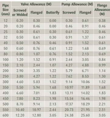
2. Additional cable is required to provide extra heat at valves, pumps and miscellaneous equipment to offset the increased heat loss associated with these items. Refer to Table 1 for estimated cable requirements for installation on typical valves and pumps. Allowances shown in Table 1 are for 150 pound valves. More cable is required for higher rated valves. Refer to heat trace isometric drawing for project specifi c allowances.
3. Install heating cable on valves and pumps utilizing a looping technique (this allows the valve or pump to be removed if required). Crossing constant watt heating cable over itself should be avoided.
4. Refer to the product specifi cations sheet for minimum bend radius for the specifi c cable type. Do not exceed bend radius when completing installation.
Table 1: Valve and Pump Allowances1
Illustration G: Typical Valve Detail Illustration H: Typical Pump Detail
Pipe Size (mm)
Valve Allowance (M) Pump Allowance (M) Flange Allowance
(M) Screwed
or Welded Flanged Butterfl y Screwed Flanged
12 0.20 0.30 0.00 0.30 0.61 0.38 20 0.20 0.46 0.00 0.46 0.91 0.46 25 0.30 0.61 0.30 0.61 1.22 0.46 32 0.50 0.61 0.30 0.91 1.37 0.61 40 0.50 0.76 0.46 0.91 1.52 0.61 50 0.60 0.76 0.61 1.22 1.68 0.69 80 0.80 1.07 0.76 1.52 2.13 0.69 100 1.20 1.52 0.91 2.44 3.05 0.84 150 2.10 2.44 1.07 4.27 4.88 0.99 200 2.90 3.35 1.22 5.79 6.71 1.14 250 3.80 4.27 1.22 7.62 8.53 1.30 300 4.60 5.03 1.52 9.14 10.06 1.52 350 5.50 5.94 1.68 10.97 11.89 1.68 400 6.60 7.01 1.83 13.11 14.02 1.83 450 7.80 8.23 1.98 15.54 16.46 1.98 500 8.70 9.14 2.13 17.37 18.29 2.21 550 10.40 10.97 2.44 20.73 21.95 2.51 600 12.20 12.80 3.05 24.38 25.60 3.05 Note . . .
1. The valve allowance given is the total amount of additional cable to be installed on the valve. If multiple tracers are used, total valve allowance may be divided among the individual tracers. The total valve allowance may be alternated among tracers for multiple valves in a heat trace circuit. Allowances are for 150 pound valves. More cable is required for higher rated valves. Refer to heat trace isometric drawing for project specifi c allowances.
Electric Heat Tracing
Completing the Installation . . .
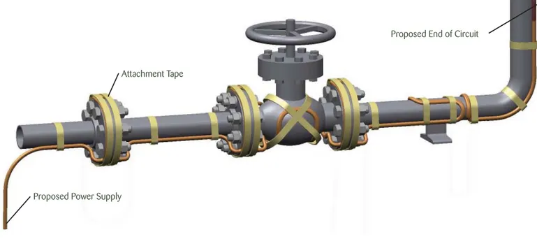
1. Begin fi nal cable attachment by securing the end-of-circuit termination kit and working back toward the power supply. Refer to Illustration I.
• Flexible heating cables are to be installed using attachment tape. Circumferential bands of tape should be installed at 30 cm intervals to keep the cable in good contact with the pipe. Refer to Table 2 below to calculate the number of rolls of attachment tape required based on the pipe diameter1.
• Avoid crossing series constant watt heating cables. • If applicable, refer to installation details provided with
the project drawings or contact Thermon for additional information regarding installation.
2. In addition to the circumferential tape requirements, a continuous covering of aluminum foil tape may be required when:
• Spray or foam2 thermal insulation is applied. • Heat tracing nonmetallic piping.
• Design requirements dictate the use of aluminum tape.
Table 2: Attachment Tape (Value Represents Approximate Linear Pipe Length Allowance Per Roll)
3. Complete splice connections (if required) in accordance with the installation instructions provided with the splice kit. 4. Before making power connections, The heating cable
should be tested to ensure electrical integrity with at least a 500 Vdc megger between the heating cable bus wires and the heating cable metallic braid. IEEE 515 and EN-IEC 60079-30 recommend that the test voltage for polymer insulated heating cables be 2500 Vdc. Minimum resistance should be 20 megohms.
(Record 2 on Insulation Resistance Test Page 9 and 10)
5. Install power connection kit in accordance to the detailed installation instructions provided with the kit.
6. Secure temperature sensor (if required) to pipe utilizing attachment tape.
Notes . . .
1. Table 2 assumes circumferential bands every 30 cm along the length of the process piping.
2. Verify exposure temperature of heating cable versus curing temperature of insulation.
Illustration I: Final Cable Attachment
Proposed End of Circuit
Attachment Tape
Proposed Power Supply
Pipe Size mm 12-25 32 40 50 80 100 150 200 250 300 350 400 450 500 600 750 Length of Pipe/ Roll of Tape m 109.7 79.2 67.0 54.9 45.7 36.6 27.4 21.3 18.2 15.2 12.2 10.7 9.1 7.6 6.0 4.6
Electric Heat Tracing
Circuit Protection Requirements . . .
1. Over-current protection (typically circuit breakers) is required for each branch circuit. This protection must isolate all power conductors from the supply.
2. For typical installations (with TT and TN grounding systems), a means of protection against earth faults is required that includes a residual-current protective device for each branch circuit. For fi xed-level earth/ground-fault circuit interrupters, a minimum 30 mA trip level is recommended. The preferred trip level for adjustable devices is 30 mA above any inherent capacitive leakage characteristic of the heater as specifi ed by the heat tracing supplier. Where conditions of maintenance and supervision ensure that only qualifi ed persons will service the installed systems, and continued circuit operation is necessary for the safe operation of the equipment or processes, earth-fault detection without interruption is acceptable if alarmed in a manner to assure an acknowledged response.
3. For IT grounding systems, a means of protection against earth faults is required that includes an electrical insulation monitoring device that shall disconnect the supply whenever the electrical resistance is not greater than 50 ohms/volt of rated voltage.
Thermal Insulation . . .
1. Before installing thermal insulation, insulation resistance test should be conducted. The cable should be tested with a test voltage of at least 500 Vdc. However, for polymer insulated heating cables, 2500 Vdc is recommended. The minimum acceptable level should not be less than 20 megohms.
2. The need for properly installed and well-maintained thermal insulation cannot be overemphasized. Without insulation, heat losses are generally too high to be offset by a conventional heat tracing system.
3. In addition to piping and in-line equipment such as pumps and valves, all heat sinks must be properly insulated. This includes pipe supports, hangers, fl anges and, in most cases, valve bonnets.
4. Regardless of the type or thickness of insulation used, a protective barrier should be installed. This protects the insulation from moisture intrusion, physical damage and helps ensure the proper performance of the heat tracing system. Seal around all penetrations through the thermal insulation.
5. Apply “Electric Heat Tracing Caution” labels to the insulation vapor barrier on 3m intervals or as required by code or specifi cation. The labels are supplied with Thermon connection kits.
Final Inspection and Documentation . . .
1. After the installation of the thermal insulation and weather barrier but BEFORE ENERGIZING THE HEATING CIRCUIT, the insulation resistance test should be
repeated. This should call attention to any damage to the heating cable that may have occurred during the insulation installation.
(Record 3 on Insulation Resistance Test Page 9 and 10.)
For Series Heating Cables, measure the electric loop resistance and record measured Ohms (Record 3 on Page 10.)
2. It is recommended that the circuit be temporarily energized so that the volts, amps, pipe temperature and ambient temperature may be recorded. Take the values after 5 minutes of energizing. This information may be of value for future reference and should be maintained for the historical operating data log.
(Record 4 on Insulation Resistance Test Page 9 and 10)
3. Stabilized design can be used for self-regulating, power-limiting and constant watt heating cables without a power-limiting device to determine the T-class through the use of the Thermon CompuTrace software or Thermon Engineering. 4. Series heating cable output and T-rating are dependent
upon supply voltage, cable resistance, temperature conditions as well as additional variables through the use of the Thermon CompuTrace software or Thermon Engineering.
5. The maximum temperatures provided by Thermon’s CompuTrace software and by Thermon engineering are calculated to the methods and requirements of EN-IEC 62086-2 and EN-IEC 60079-30.
6. If stabilized design is used, the end user must record the system parameters and the area T-class, and keep these records for the time the heating cable is in operation. 7. Inspect system on a regular basis at least once per year.
Record all information after conducting test. If the system fails any test, refer to Thermon’s Maintenance and Trouble Shooting Guide for assistance. De-energize circuits affected and make the necessary repairs immediately.
8. Verify the setting of the maximum control device, if provided to limit the T-rating for the circuit design, to ensure it limits the maximum surface temperature to be in compliance with clause 4.4.3 of EN-IEC 60079-30-1.
Maintenance and Repair . . .
1. Refer to form TEP0066-Electric Heat Tracing Maintenance and Trouble Shooting Guide.
Cable Testing Report
1. Refer to these Installation Procedures for general installation procedures, requirements and guidelines.
2. Upon receiving heating cable, check the cable to make sure the proper type and output have been received. All fl exible cables have the catalog number, voltage rating and watt output printed on the outer jacket.
3. Visually inspect cable for any damage incurred during shipment. The heating cable should be tested to ensure electrical integrity with at least a 500 Vdc megger between the heating cable bus wires and the heating cable metallic braid. IEEE 515 and EN-IEC 60079-30 recommend that the test voltage for polymer insulated heating cables be 2500 Vdc. Minimum resistance should be 20 megohms.
(Record 1 on Insulation Resistance Test Page 9 and 10)
A. Connect the positive lead of the megger to the cable bus wires.
B. Connect the negative lead of the megger to the metallic braid. C. Energize the megger and record the reading. Readings
between 20 megohms and infi nity are acceptable. Readings below 20 megohms may mean the electrical insulation has
been damaged. Recheck the heating cable for physical damage between the braid and the heating element; small cuts or scuffmarks on the outer jacket will not affect the megger reading unless there was actual penetration through the braid and dielectric insulation jacket.
4. Once the installation is complete, but prior to installation of thermal insulation, recheck the heating cable with at least a 500 Vdc megger between the heating cable bus wires and the heating cable metallic braid. IEEE 515 and EN-IEC 60079-30 recommend that the test voltage for polymer insulated heating cables be 2500 Vdc. Minimum resistance should be 20 megohms. (Record 2 on Insulation Resistance Test Page 9 and 10)
5. After the thermal insulation is installed, the insulation resistance test should be repeated. Minimum resistance should be 5 megohms. (Record 3 on Insulation Resistance Test Page 9 and 10.) For Series Heating Cables, measure the electric loop resistance and record measured Ohms (Record 3, Page 10.)
6. After the thermal insulation is installed and power supply is completed, record the panel and circuit breaker information. Ensure all junction boxes, temperature controllers, cable glands, etc. are properly secured. Set the temperature controller (if applicable) to the manual setting and apply rated voltage to the heat tracing circuit(s) for 5 minutes. Record the ambient temperature, measure and record the circuit(s) voltage and current.
(Record 4 on Insulation Resistance Test Page 9 and 10)
NOTE: To ensure the heating cable warranty is maintained through installation, the testing outlined
on this sheet must be completed on the installed heating cables.
Checklist for Self-Regulating and Power-Limiting Heat Tracing
General Information
Project Number:
Installation
Contractor:
Unit Number:
Thermon Reference
Number:
Customer Ref. Number:
Inspector:
Record 1: Prior to Installation
Cable Type:
Reel Number:
Reel Length (M):
Insulation Resistance:
(M Ohms)*
Tested By/Date:
Witnessed By/Date:
Record 2: After Cable Installation
Line Number:
Thermostat Number:
Equipment Number:
Junction Box Number:
Circuit/Heater Number:
Unused Entries
Plugged Off:
Circuit Switch Number:
Heater Length (M):
Metal Sheath Connected
to Earth/Ground:
Insulation Resistance:
(M Ohms)*
Tested By/Date:
Witnessed By/Date:
Record 3: After Thermal Insulation is Installed
Insulation Watertight:
Insulation Resistance:
(M Ohms)*
Tested By/Date:
Witnessed By/Date:
Record 4: Final Commissioning
Panel Number:
Ambient Temp. (°C):
Breaker Number:
Pipe Temp. (°C):
Volts:
Recorded Amps
(after 5 min.):
Tested By/Date:
Witnessed By/Date:
*NOTE: Minimum acceptable insulation resistance should be 20 megohms for Records 1 and 2 and
5 Megohms for Record 3.
Checklist for Installation of Series Heating Cables
General Information
Project Number:
Electrical Contractor:
Unit Number:
Reference Number:
Customer Ref. Number:
Inspector:
Record 1: Prior to Installation
Cable Type:
Insulation Resistance (M Ohms):
Reel Length (M):
1 2Single Phase
L-Earth
3 Phase
L
1-Earth
Reel Number:
1 2L
2-Earth
L
3-Earth
Tested By/Date:
Witnessed By/Date:
Record 2: After Cable Installation
Line Number:
Junction Box Number:
Equipment Number:
Unused Entries
Plugged Off:
Circuit/Heater Number:
Heater Length (M):
1 2Circuit Switch Number:
Insulation Resistance (M Ohms):
Braid Connected
to Earth/Ground:
Single Phase
L-Earth
3 Phase
L
1-Earth
Thermostat Number:
L
2-Earth
L
3-Earth
Tested By/Date:
Witnessed By/Date:
Record 3: After Thermal Insulation is Installed
Insulation Watertight:
Insulation Resistance (M Ohms):
Electrical Loop Resistance (Ohms):
Single Phase
L-Earth
Single Phase
L-L
3 Phase
L
1-Earth
3 Phase
L
1-L
2L
2-Earth
L
2-L
3L
3-Earth
L
3-L
1Tested By/Date:
Witnessed By/Date:
Record 4: Final Commissioning
Panel Number:
Ambient Temp. (°C):
Breaker Number:
Pipe Temp. (°C):
Volts:
Recorded Amps
(after 5 min.):
Tested By/Date:
Witnessed By/Date:
THERMON . . . The Heat Tracing Specialists® www.thermon.com
Corporate Headquarters 100 Thermon Dr.
•
PO Box 609 San Marcos, TX 78667-0609•
USA Phone: +1 512-396-5801European Headquarters Boezemweg 25
•
PO Box 205 2640 AE Pijnacker•
The Netherlands Phone: +31 (0) 15-36 15 370For the Thermon offi ce nearest you visit us at . . .
www.thermon.com For additional product information on Thermon heating cables, refer to the individual product specifi cations.
BSX™ (refer to Form TEP0067U) RSX™ 15 (refer to Form TEP0048U) HTSX™ (refer to Form TEP0074U) KSX™ (refer to Form TEP0072U) VSX™ (refer to Form TEP0008U) HPT™ (refer to Form TEP0011U) FP (refer to Form TEP0016U) HTEK™ (refer to Form TEP0022U) TEK™ (refer to Form TEP0021U) TESH™ (refer to Form TEP0070U)