International Journal of Science Engineering and Advance Technology,
IJSEAT, Vol 4, Issue 1
ISSN 2321-6905
January - 2016
Thermal Analysis of Single Pass GRITH Weld for Different Materials
1Ramanaji Koneti 2A.V.Sridhar 3K.Mohan Krishna 4J Hari Narayana Rao1
M. Tech. Student, 2Associate.Professor,3Assistant.Professor Dept Of ME, KITS , DIVILI
4Reserch Scholar
ABSTRACT:
Girth welds are the different types of arc welding processes applied in the joining of two pipes along the circumference during a phase construction of a pipeline depending on the ease of implementation and the environmental factor. They are used in making circumferential welds in pipeline and underground systems. They are used in the pipeline industry.
Here in this project we have designed a pipe which has be welded to a flange by single pass girth welding. Here we are going to consider two welding cases i.e. normal welding process and welding with an Al block under the welding portion. We are going to consider these two welding conditions for girth welding of the pipe made of two different materials i.e. Stainless Steel and Carbon steel alloy.
Thermal analysis is done to the product to study the weld behavior of the component. The Component is designed in CATIA V5 and Thermal analysis is carried out in ANSYS.
1. INTRODUCTION
GIRTH WELDS
Girth welds are the different types of arc welding processes applied in the joining of two pipes along the circumference during a phase construction of a pipeline depending on the ease of implementation and the environmental factor [1,2].
They are used in making circumferential welds in pipeline and underground systems. They are used in the pipeline industry in the following activities:[3,4]
• Main-line welding
• Tie-in welding
• Repair welding
• Fabrication welding
In girth welds, the welder has to make several passes to make it a perfect and sealed joint. The welder has to first make a root pass—the most difficult pass—
at a specified speed. The second pass is a hot pass that increases the thickness of the fill. Finally, the third pass is the fill and cap pass that is made to finish the welding process by covering the joint [5,6].
The mode of welding or the standards set for girth welds are determined by:
The joint strength of the pipes based on the base material
The joint strength based on the external conditions
The method of pipe manufacturing process
The pipe wall thickness and its diameter
The length of the pipeline/cost
The terrain and environmental factors
The workmanship of the welder
2. DESIGN AND MATERIAL PROPERTIES
2.1 MATERIAL PROPERTIES
STAIN LESS STEEL
THERMAL CONDUCTIVITY: 15.1W/moC
LOW CARBON STEEL
THERMAL CONDUCTIVITY: 36W/mK
CARBON STEEL ALLOY
THERMAL CONDUCTIVITY: 50W/mk
2.2 DESIGN
International Journal of Science Engineering and Advance Technology,
IJSEAT, Vol 4, Issue 1
ISSN 2321-6905
January - 2016
Fig. Drafting of pipe- flange assembly
2.2.2 3d Design Model
Fig1 Designing of flange
Fig2 Designing of pipe
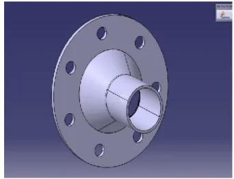
Fig3 Designing of pipe-flange assembly
3. ANALYSIS
IMPORTED MODEL
Fig4 Import model of directed welded stainless steel pipe
MESH MODEL
International Journal of Science Engineering and Advance Technology,
IJSEAT, Vol 4, Issue 1
ISSN 2321-6905
January - 2016
INPUT DATA
Fig6 Temperature input to model of directed welded stainless steel pipe
Fig7 Convection data input to model of directed welded stainless steel pipe
TEMPERATURE
Fig8Temperature of directed welded stainless steel pipe
TOTAL HEAT FLUX
Fig9 Total heat flux of directed welded stainless steel pipe
DIRECTIONAL HEAT FLUX
Fig10 Directional heat flux of directed welded stainless steel pipe
4. REPORT
Thermal Analysis Of Single Pass Girth Welding
TEMP ERAT URE
HEAT FIUX
DIRECTI ONAL HEAT FLUX M
I N
M A X
MI N
M AX
MI N
M AX
NO RM AL WE LD
STAINL ESS STEEL
6 0 0. 2 1
1 6 5 4
3.0 8E-07
2.1 9E +0 6
-1.3 8E+ 06
7.3 1E +0 5
International Journal of Science Engineering and Advance Technology,
IJSEAT, Vol 4, Issue 1
ISSN 2321-6905
January - 2016
N STEEL ALLOY 0 3 8 6 5 3. 1 8E-07 3E +0 6 1.1 6E+ 06 6E +0 5 AL BLO CK WE LD STAINL ESS STEEL 2 4 3. 2 9 1 7 4 6. 5 0.0 004 85 8.1 4E +0 6 -2.5 4E+ 06 6.9 2E +0 5 CARBO N STEEL ALLOY 5 0 7. 5 1 7 3 4. 3 0.0 013 59 9.1 1E +0 6 -6.6 8E+ 06 1.8 9E +0 6 Table 1 Thermal Analysis result for Single pass girth
welded pipe
Thermal Analysis When Fluid Flows In This Pipe
TEMPERAT URE TOTAL HEAT FLUX DIRECTIO NAL HEAT FLUX MIN MA X MIN MA X MIN MA X STAIN LESS STEEL 790. 15 800. 11 0.003 574 498 8.5 -4702 .7 4607 .9 CARB ON STEEL 790. 15 800. 04 0.002 181 433 3.9 -2874 .6 2394 .3
Table 2 Thermal Analysis result for Single pass girth welded pipe when fluid flows
5. THERMAL ANALYSIS GRAPHS FOR STAINLESS STEEL PIPE
TEMPERATURE
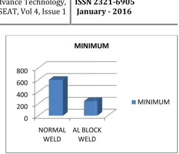
Graph1 : Min Temperature vs. Weld type for stainless steel pipe
Graph2 : Max Temperature vs. Weld type for stainless steel pipe
HEAT FLUX
International Journal of Science Engineering and Advance Technology,
IJSEAT, Vol 4, Issue 1
ISSN 2321-6905
January - 2016
N STEEL ALLOY 0 3 8 6 5 3. 1 8E-07 3E +0 6 1.1 6E+ 06 6E +0 5 AL BLO CK WE LD STAINL ESS STEEL 2 4 3. 2 9 1 7 4 6. 5 0.0 004 85 8.1 4E +0 6 -2.5 4E+ 06 6.9 2E +0 5 CARBO N STEEL ALLOY 5 0 7. 5 1 7 3 4. 3 0.0 013 59 9.1 1E +0 6 -6.6 8E+ 06 1.8 9E +0 6 Table 1 Thermal Analysis result for Single pass girth
welded pipe
Thermal Analysis When Fluid Flows In This Pipe
TEMPERAT URE TOTAL HEAT FLUX DIRECTIO NAL HEAT FLUX MIN MA X MIN MA X MIN MA X STAIN LESS STEEL 790. 15 800. 11 0.003 574 498 8.5 -4702 .7 4607 .9 CARB ON STEEL 790. 15 800. 04 0.002 181 433 3.9 -2874 .6 2394 .3
Table 2 Thermal Analysis result for Single pass girth welded pipe when fluid flows
5. THERMAL ANALYSIS GRAPHS FOR STAINLESS STEEL PIPE
TEMPERATURE
Graph1 : Min Temperature vs. Weld type for stainless steel pipe
Graph2 : Max Temperature vs. Weld type for stainless steel pipe HEAT FLUX 0 200 400 600 800 NORMAL
WELD AL BLOCKWELD
MINIMUM 1600 1650 1700 1750 NORMAL
WELD AL BLOCKWELD MAXIMUM 0.00E+001.00E-04 2.00E-04 3.00E-04 4.00E-04 5.00E-04 MINIMUM
International Journal of Science Engineering and Advance Technology,
IJSEAT, Vol 4, Issue 1
ISSN 2321-6905
January - 2016
N STEEL ALLOY 0 3 8 6 5 3. 1 8E-07 3E +0 6 1.1 6E+ 06 6E +0 5 AL BLO CK WE LD STAINL ESS STEEL 2 4 3. 2 9 1 7 4 6. 5 0.0 004 85 8.1 4E +0 6 -2.5 4E+ 06 6.9 2E +0 5 CARBO N STEEL ALLOY 5 0 7. 5 1 7 3 4. 3 0.0 013 59 9.1 1E +0 6 -6.6 8E+ 06 1.8 9E +0 6 Table 1 Thermal Analysis result for Single pass girth
welded pipe
Thermal Analysis When Fluid Flows In This Pipe
TEMPERAT URE TOTAL HEAT FLUX DIRECTIO NAL HEAT FLUX MIN MA X MIN MA X MIN MA X STAIN LESS STEEL 790. 15 800. 11 0.003 574 498 8.5 -4702 .7 4607 .9 CARB ON STEEL 790. 15 800. 04 0.002 181 433 3.9 -2874 .6 2394 .3
Table 2 Thermal Analysis result for Single pass girth welded pipe when fluid flows
5. THERMAL ANALYSIS GRAPHS FOR STAINLESS STEEL PIPE
TEMPERATURE
Graph1 : Min Temperature vs. Weld type for stainless steel pipe
International Journal of Science Engineering and Advance Technology,
IJSEAT, Vol 4, Issue 1
ISSN 2321-6905
January - 2016
Graph3: Min Heat flux vs. Weld type for stainless steel pipe
Graph4 Max Heat flux vs. Weld type for stainless steel pipe
DIRECTIONAL HEAT FLUX
Graph5 Min Directional Heat flux vs. Weld type for stainless steel pipe
Graph6 Max Directional Heat flux vs. Weld type for stainless steel pipe
CONCLUSION
Here in this project we have designed a pipe which has be welded to obtain as a pipe, so here for welding purpose we are going to use low carbon steel. So here we have designed a pipe with stain less steel and welded with low carbon steel and the other model is manufactured with carbon steel and welded with low carbon steel alloy. And the same procedure is repeated in which an AL block is present under the welding portion. And thermal analysis is done to the product
As if we observe in the product which is welded under normal welding conditions and welded in which an AL block is located under the welding portion as to dissipate the heat easily. So as from the analysis, if we observe the tables and graphs, we can conclude that the pipe manufactured with carbon steel alloy and welded with low carbon in which an AL block is placed is the best material as the heat dissipation is very fast from the pipe while welding, so by this process the pipe can withstand high pressure and temperatures and give better life efficiency.
As from the analysis of the fluid flow from the pipe after welding, as if we observe the obtained tables and graphs, we can conclude that the pipe welded with low carbon and made with carbon steel is the best material as it is having the less heat flux on the product, so here we can conclude that the this i the best material with best life output.
REFERENCES
[1] Welding: Principles and Applications by Larry F. Jeffus, Cengage Learning, 01-Sep-1997 How To Weld by MBI, 2008
[2] Pipe Welding Procedures by HoobasarRampaul, Industrial Press Inc., 2003
[3]Aluminum Welding by N. R. Mandal, Woodhead Publishing, 01-Jan-2001
[4]Trends In Welding Research: Proceedings of the 7Th International Conference by Stan A. David, ASM International, 2006
[5] The Science and Practice of Welding by A. C. Davies, Cambridge University Press, 1992
[6] Welded Joint Design by John G. Hicks, Woodhead Publishing, 1999
0.00E+00 2.00E+06 4.00E+06 6.00E+06 8.00E+06 1.00E+07
NORMAL WELD AL BLOCKWELD
MAXIMUM
-3.00E+06 -2.00E+06 -1.00E+06 0.00E+00
MINIMUM
6.60E+05 6.80E+05 7.00E+05 7.20E+05 7.40E+05
MAXIMUM
International Journal of Science Engineering and Advance Technology,
IJSEAT, Vol 4, Issue 1
ISSN 2321-6905
January - 2016
Graph3: Min Heat flux vs. Weld type for stainless steel pipe
Graph4 Max Heat flux vs. Weld type for stainless steel pipe
DIRECTIONAL HEAT FLUX
Graph5 Min Directional Heat flux vs. Weld type for stainless steel pipe
Graph6 Max Directional Heat flux vs. Weld type for stainless steel pipe
CONCLUSION
Here in this project we have designed a pipe which has be welded to obtain as a pipe, so here for welding purpose we are going to use low carbon steel. So here we have designed a pipe with stain less steel and welded with low carbon steel and the other model is manufactured with carbon steel and welded with low carbon steel alloy. And the same procedure is repeated in which an AL block is present under the welding portion. And thermal analysis is done to the product
As if we observe in the product which is welded under normal welding conditions and welded in which an AL block is located under the welding portion as to dissipate the heat easily. So as from the analysis, if we observe the tables and graphs, we can conclude that the pipe manufactured with carbon steel alloy and welded with low carbon in which an AL block is placed is the best material as the heat dissipation is very fast from the pipe while welding, so by this process the pipe can withstand high pressure and temperatures and give better life efficiency.
As from the analysis of the fluid flow from the pipe after welding, as if we observe the obtained tables and graphs, we can conclude that the pipe welded with low carbon and made with carbon steel is the best material as it is having the less heat flux on the product, so here we can conclude that the this i the best material with best life output.
REFERENCES
[1] Welding: Principles and Applications by Larry F. Jeffus, Cengage Learning, 01-Sep-1997 How To Weld by MBI, 2008
[2] Pipe Welding Procedures by HoobasarRampaul, Industrial Press Inc., 2003
[3]Aluminum Welding by N. R. Mandal, Woodhead Publishing, 01-Jan-2001
[4]Trends In Welding Research: Proceedings of the 7Th International Conference by Stan A. David, ASM International, 2006
[5] The Science and Practice of Welding by A. C. Davies, Cambridge University Press, 1992
[6] Welded Joint Design by John G. Hicks, Woodhead Publishing, 1999
MAXIMUM
MINIMUM
MAXIMUM
International Journal of Science Engineering and Advance Technology,
IJSEAT, Vol 4, Issue 1
ISSN 2321-6905
January - 2016
Graph3: Min Heat flux vs. Weld type for stainless steel pipe
Graph4 Max Heat flux vs. Weld type for stainless steel pipe
DIRECTIONAL HEAT FLUX
Graph5 Min Directional Heat flux vs. Weld type for stainless steel pipe
Graph6 Max Directional Heat flux vs. Weld type for stainless steel pipe
CONCLUSION
Here in this project we have designed a pipe which has be welded to obtain as a pipe, so here for welding purpose we are going to use low carbon steel. So here we have designed a pipe with stain less steel and welded with low carbon steel and the other model is manufactured with carbon steel and welded with low carbon steel alloy. And the same procedure is repeated in which an AL block is present under the welding portion. And thermal analysis is done to the product
As if we observe in the product which is welded under normal welding conditions and welded in which an AL block is located under the welding portion as to dissipate the heat easily. So as from the analysis, if we observe the tables and graphs, we can conclude that the pipe manufactured with carbon steel alloy and welded with low carbon in which an AL block is placed is the best material as the heat dissipation is very fast from the pipe while welding, so by this process the pipe can withstand high pressure and temperatures and give better life efficiency.
As from the analysis of the fluid flow from the pipe after welding, as if we observe the obtained tables and graphs, we can conclude that the pipe welded with low carbon and made with carbon steel is the best material as it is having the less heat flux on the product, so here we can conclude that the this i the best material with best life output.
REFERENCES
[1] Welding: Principles and Applications by Larry F. Jeffus, Cengage Learning, 01-Sep-1997 How To Weld by MBI, 2008
[2] Pipe Welding Procedures by HoobasarRampaul, Industrial Press Inc., 2003
[3]Aluminum Welding by N. R. Mandal, Woodhead Publishing, 01-Jan-2001
[4]Trends In Welding Research: Proceedings of the 7Th International Conference by Stan A. David, ASM International, 2006
[5] The Science and Practice of Welding by A. C. Davies, Cambridge University Press, 1992