On-Chip AHB Bus Trace Analyzer for Real Time Tracing With
Lossless Data Compression
N.Rajesh Babu, M.Srinu Associate Professor, P.G Student
Department of Electronics and Communication Engineering Sri Sai Aditya Institute of Science and Technology
ABSTRACT
The advanced micro controller bus Architecture (AMBA) is widely used as the on-chip bus in System-on-Chip(SoC) designs. The important aspect of a SoC is not only which components or blocks it houses, but also how they are interconnected. AMBA is a solution for the blocks to interface with each other. The objective of the AMBA specification is to be technology independent, minimize silicon infrastructure while supporting high performance and low power on-chip communication. The biggest challenge in SoC design is in validating and testing the system.
The Advanced High-performance Bus (AHB) is a part of the Advanced Microcontroller Bus Architecture (AMBA). Performance can be improved at high-frequency operation. Performance is independent of the mark-space ratio of the clock. No special considerations are required for automatic test insertion. Our aim in this project is to design the AHB- protocol with bus tracer. For real-time tracing, we should reduce the trace size as much as possible without reducing the original data.
The experimental results show that trace compression ratio reduced by 96.32%. Finally this approach was designed successfully along with MODEL SIM and synthesis using Xilinx ISE. The SoC can be verified in field-programmable gate array.
1. INTRODUCTION
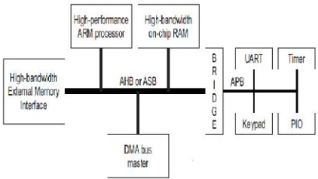
The Advanced Microcontroller Bus Architecture (AMBA) specification defines an on-chip communication standard for designing high-performance embedded microcontrollers. The AHB acts as the high-performance system backbone bus. AHB supports the efficient connection of processors, on-chip memories and off-chip external memory interfaces with low-power peripheral macrocell functions. AHB is also specified to ensure ease of use in an efficient design flow using synthesis and automated test techniques.
Fig 1. A Typical AMBA AHB based system
The spirit of a hardware tracer is how to reduce the data using Compression mechanism. There are hardware approaches to compress the trace, which can be divided in lossy and lossless categories. Some appropriate compressing methods have been available for different types and parts of bus signals. Branch/target filtering is one common technique for program address compression. This approach has been used in some commercial processors, such as TriCore
and ARM’s Embedded Trace Macrocell.Thehardware overhead of these works is small since the filtering mechanism is simple to implement in hardware. However, the effectiveness of these techniques is mainly limited by the average basic
block size, which is roughly around four or five instructions per basic block, as reported in and for data address and value tracing, the most popular method is used the differential approach based on subtraction. Some researches have shown that using the differential method can reduce the data address and data values traces by about 40 percent and 14 percent respectively. Besides the address and data bus, there are several control signals on system bus that need to be traced. Some FPGA boards have built-in signal trace tools, such as the Altera Signal Tap and Xilinx Chip- Scope. FS2 AMBA Navigator supports bus clock mode and bus transfer mode to trace bus signals on every clock and bus transfer respectively. Trace buffer stores bus cycles or bus transfers based on local internal memory size. Although these approaches support multiple trace modes such as tracing at cycle by-cycle or at signal transaction, only one mode can use during a tracing process. This paper presents the multi-resolution approach that can use different trace modes during a bus signal tracing process.
3. AMBA BUS TRACER ARCHITECTURE
This section presents the architecture of our bus tracer. Shown in Fig.1 is the bus tracer overview. It mainly contains four parts 1)Event Generation Module 2)Abstraction Module 3)Compression Modules and 4) Packing Module. The Event Generation Module controls the start/stop time, the trace mode, and the trace depth of traces. The signal Abstraction module traces the corresponding AHB signals at proper time according to user configuration. The trace compression module compresses the trace data in accordance with signal characteristics. Finally, in the data packing module, the trace data is arranged compactly for output to the internal on-chip trace memory or external off-chip storage.
Fig.2.Multiresolution Bus Tracer Block Diagram The transaction-level debugging provides software and hardware designers a common abstraction level to diagnose bugs. The abstraction level is in two dimensions timing abstraction and signal abstraction. The timing dimension has two abstraction levels which are the cycle level and transaction. level. The cycle level captures the signals at every cycle. The transaction level records the signals only when their value changes.
The signal dimension involves grouping of AHB bus signals into four categories: program address, data address/value, access control signals (ACS), and protocol control signals (PCS). Then, we define three abstraction levels for those signals. The master state level further abstracts the bus state level by only recording the transfer activities of bus masters and ignoring the handshaking activities within transactions. This level also ignores the signals when the bus state is IDLE, WAIT, and BUSY. The BSM is designed based on the AMBA AHB 2.0 protocol to represent the key bus handshaking activities within a transaction.
32 bits
Address
Address Mask
Data
Data Mask
Control
Control Mask
Trace Depth
Trace Mode( 4bits)
Direc tion
Ena ble
A H B Bu s
Chec ker Event
Even t Num bers (24 bits)
Event Numbers(21 bits) [10:0] zeros
2. Abstraction Module: The Abstraction Module monitors the AMBA bus and selects/filters signals based on the abstraction mode. The abstraction mechanism deals with the trace granularity and trace depth.
In abstraction mode we provide five modes in different granularities. They are Mode 1 (full signal,
transaction level), and Mode 5 (master state, transaction level).
Fig.3. timing abstraction level mechanism
At Mode 1, the tracer traces all bus signals step by step so the detailed bus activities can be observed.
At Mode 2, the tracer traces all signals only when their values are differed.
At Mode 3, the tracer uses the Bus State Machine, such as NORMAL, IDLE, ERROR, and so on, to represent bus transfer activities in cycle changing level. Comparing to mode FC designers can observe the bus handshaking states without analyzing the detail signals.
At Mode 4, the tracer uses bus state to represent bus transfer activities in transaction level Our bus tracer also supports dynamic mode change (DMC) feature which allows designers to change the trace mode dynamically in real-time.
Fig.4.Debugging/monitoring process with dynamic mode change
3. Compression Module: The purpose of Compression Module is to reduce the trace size. It accepts the signals
levels pipeling stages has been indicated.Using pipeling stage it improves overall capability of the systems
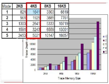
Fig.4. Trace Memory Vs Trace size
When the on chip trace memory is full, it sends an interrupt to the microprocessor then this processor reads the data from the trace memory and transfers the trace data to off-chip storage through AMBA.
4) Packing Module: The Packing Module is the last phase. It receives the compressed data from the compression module, processes them, and writes them to the trace memory.
Fig.5.Concatenation of mode-change packet for abstraction mode switch
4. AHB Protocol checker (HP checker)
Checker is an external module from where we can trace data other than AHB bus.
Fig. 5: Protocol Checker
AHB Protocol Checker (HP Checker) architecture, contains two main function blocks: Protocol Checker, ERROR Reference.
Protocol Checker is the main core of HP Checker, the inputs are all AHB bus signals, and the outputs are ERROR signals and corresponding master and slave IDs. Every rule has its own corresponded bit because every cycle maybe occur more than one error.
HP Checker is a rule-based protocol checker, thus how to establish a set of well-defined rules is very important.
5. EXPERIMENTAL RESULTS
By simulation and synthesis the following results are obtained for each cycle at different
abstraction levels. Here Modelsim tool is used in order to simulate the design and Xilinx tool for Synthesis process and the netlist generation.
Event Generator
Abstraction
Compression
Packing
Synthesis
Result:-We synthesized this code by using XILINX ISE 9.2 verification, and implementation of digital logic chips at the Register transfer level (RTL) level of abstraction by using XILINX ISE 9.2
RESULT:-Timing
Summary:-Minimum period: 5.654ns (Maximum Frequency: 176.864MHz)
Minimum input arrival time before clock: 7.141ns
Maximum output required time after clock: 6.978ns
Maximum combinational path delay: 8.227ns
CONCLUSION
AHB bus is capable of achieving high performance with a maximum frequency of 176.864MHz.The bus traces with 5 modes of resolution and the design is verified for all cases of 5 modes. With the aforementioned features, SYS-HMRBT supports a diverse range of design/debugging/ monitoring activities, including module development, chip integration, hardware/software integration and debugging, system behavior monitoring, system performance/power analysis and optimization, etc. The users are allowed to tradeoff between trace granularity and trace depth in order to make the most use of the on-chip trace memory or I/O pins. The reason is that this paper optimizes the pingpong architecture by sharing most of the data path.
FUTURE SCOPE
In the future, we would extend this work to more advanced buses/connects such as AXI or OCP. In addition, with its real time abstraction capability, we would like to explore the possibility of bridging our bus tracer with ESL design methodology for advanced hardware/software procure development/debugging/ monitoring/analysis.
REFERENCES
1.
An On-Chip AHB Bus Fu-Ching Yang, Member, IEEE, Yi-Ting Lin, Chung-Fu Kao, and Ing-Jer Huang IEEE TRANSACTIONS ON VERY LARGE SCALE INTEGRATION (VLSI) SYSTEMS, VOL. 19, NO. 4, APRIL 20112.
ARM Ltd., San Jose, CA, ―ARM. AMBAAHB Trace Macrocell (HTM) technical reference manual ARM DDI 0328D, 2007.
3.
B. Vermeulen, K. Goosen, R. van Steeden, andM. Bennebroek, “Communication- centric SoC
debug using transactions,” in Proc. 12th IEEE
Eur. Test Symp., May 20–24, 2007, pp. 69–76.
4.
ARM Ltd., San Jose, CA, “Embedded trace macro cell architecture specification,” 2006.5.
First Silicon Solutions (FS2) Inc., Sunnyvale,CA, “AMBA navigator spec sheet,” 2005.
6.
B. Tabara and K. Hashmi, “Transaction-level modelling and debug of SoC's,” presented atthe IP SoC Conf., France, 2004
7.
Infineon Technologies, Milipitas, CA, “TC1775Tri-Core user's manual system units,” 2001.
8.
E. E. Johnson, J. Ha, and M. B. Zaidi,Lossless trace compression,‖ IEEE Trans. Comput., vol. 50, pp. 158–173, Feb. 20019.
ARM Ltd., San Jose, CA, “AMBA Specification (REV 2.0) ARM IHI0011A,”1999.
10.
E. Rotenberg, S. Bennett, and J. E. Smith, “A trace cache micro architecture and evaluation,”IEEE Trans. Comput., vol. 48, no. 1, pp. 111–
120, Feb. 1999.