Sorption-based Energy Storage Systems: A Review
Kyaw Thu
1,2*, Nasruddin
3*, Sourav Mitra
4, and Bidyut Baran Saha
5,61. Department of Advanced Environmental Science and Engineering, Faculty of Engineering Sciences, Kyushu University, 6-1, Kasuga-koen, Kasuga-shi, Fukuoka 816-8580, Japan
2. Green Asia Education Center, Interdisciplinary Graduate School of Engineering Sciences, Kyushu University, Kasuga-koen 6-1, Kasuga-shi, Fukuoka 816-8580, Japan
3. Department of Mechanical Engineering, Faculty of Engineering, Universitas Indonesia, Depok 16424, Indonesia 4. Department of Mechanical Engineering, Indian Institute of Technology, Kharagpur 721302, India 5. International Institute for Carbon-Neutral Energy Research (WPI-I2CNER), Kyushu University, 744 Motooka,
Nishi-ku, Fukuoka 819-0395, Japan
6. Mechanical Engineering Department, Kyushu University, 744 Motooka, Nishi-ku, Fukuoka 819-0395, Japan
*e-mail: kyaw.thu.813@m.kyushu-u.ac.jp, nasruddin@eng.ui.ac.id
Abstract
Mismatched timing between the supply and demand of energy calls for reliable storage systems. Energy storage systems have become further significant with the widespread implementation of renewable energy. These systems can mitigate problems that are often associated with renewable energy sources such as supply unreliability while meeting the de-mand during peak hours. Energy can be stored in various forms, yet storage systems can be generally grouped based on their output forms, namely (i) electricity and (ii) heat or thermal energy. Electrical energy is the most convenient and effective form since it can power almost all modern devices. However, the electricity itself is vastly produced by ther-modynamic cycles at a particular thermal efficiency using thermal energy from fossil fuels. Meanwhile, thermal energy for the HVAC&R and the production of hot water remains the largest portion of the building energy sector. Thermal energy can be stored in the form of sensible, latent, and thermochemical energy. This review focuses on thermochemi-cal sorption-based energy storage systems. These systems exploit endothermic and exothermic sorption processes for charging and discharging of the thermal energy. Sorption-based storage systems exhibit huge potential due to a high energy density and their ability to store the energy at room temperature. We discuss the current state-of-the-art develop-ments, key challenges, and future prospects of sorption-based energy systems.
Abstract
Sistem Penyimpanan Energi Berbasis Penyerapan: Suatu Kajian. Ketidakserasian waktu antara suplai dan per-mintaan energi menuntut sistem penyimpanan yang andal. Sistem-sistem penyimpanan energi menjadi semakin signif-ikan dengan implementasi yang meluas energi yang dapat diperbaharui. Sistem-sistem ini dapat mengurangi masalah seperti ketidakandalan suplai ketika memenuhi permintaan selama jam-jam puncak yang seringkali disatukan dengan sumber-sumber energi yang dapat diperbaharui. Sekalipun demikian, energi yang dapat disimpan dalam bentuk sistem penyimpan umumnya dapat dikelompokkan berdasarkan pada bentuk outputnya yaitu: (i) elektrisitas dan (ii) panas atau energi termal. Energi listrik merupakan bentuk energi yang paling nyaman dan efektif karena energi listrik dapat meng-gerakkan hampir semua alat-alat modern. Namun demikian, elektrisitas itu sendiri diproduksi dengan cepat melalui si-klus termodinamik dengan suatu efisiensi termal tertentu dengan menggunakan energi termal yang berasal dari bahan ba-kar fosil. Sementara, energi termal untuk HVAC&R dan produksi air panas masih merupakan bagian terbesar dari sektor energi bangunan. Energi termal dapat disimpan dalam bentuk panas sensibel, panas laten, dan termokimia. Pertimbangan ini memfokuskan pada sistem-sistem penyimpanan energi berbasis penyerapan yang merupakan sistem penyimpanan tipe termokimia. Sistem ini mengeksploitasi proses penyerapan endotermis dan eksotermis untuk mengisi dan menge-luarkan energi panas. Sistem penyimpanan berbasis penyerapan memperlihatkan potensi yang sangat besar karena kerapatan energi dan kemampuannya untuk menyimpan energi pada temperatur ruang. Kami mengkaji latar belakang teknologi ini, perkembangannya saat ini, kendala kunci dan aspek-aspek masa depan dari sistem penyimpanan energi berbasis penyerapan.
1.
Introduction
Modern society is strongly associated with energy. Elec-tricity and energy help mankind defy nature. Thermal comfort and the ability to preserve food and medications undoubtedly contribute to extending the life expectancy and improving living standards. Over recent decades, fossil fuels combustion has dominated energy produc-tion. Energy generation by fossil fuels offers several advantages, including reliability and scalability (from micro to mega scales). However, the second law of thermodynamics dictates power generation processes by thermodynamic cycles, where the heat rejection to the sink is inevitable [1]. The result is greenhouse gas emis-sion and global warming from the energy-related activi-ties. Recently, generation using renewable energy has been introduced as a favorable alternative. An energy source can be considered renewable if it is naturally replenished and inexhaustible [2]. Renewable energy sources include wind, hydropower, geothermal energy, biomass, and solar power, which is the major source. However, renewable energy sources are associated with unreliability and supply/demand time gap. In other words, unlike the burning of fossil fuels, most renewa-ble energy sources are not always availarenewa-ble at the time of demand. Meanwhile, daily and seasonal variation of the solar power can be traced back to the mechanism of the planetary system. The rotation of the earth while it revolves around the sun determines the availability of the solar energy at a particular place on the planet. Thus, it is rather natural that in most cases a storage system is required to realize continuous power supply from the renewable energy source.
The idea of energy storage itself has been known since prehistoric ages, where energy was stored in the form of dry wood and preserved seeds. Modern energy storage systems can be grouped according to the form of energy discharge, which includes electricity and heat. Figure 1 shows a conceptual diagram for such energy storage systems. Batteries [3], supercapacitors, hydrogen fuel cells, compressed air, flywheels, and pumped hydro-power [4] are examples of systems that store energy and discharge electricity. Lithium-ion batteries offer effi-cient energy storage and great portability, and nowa-days, they power almost all mobile devices, such as smartphones and portable computers, to electric vehi-cles. Moreover, lithium-ion batteries allow for localized zero emissions, as in electric vehicles; such vehicles significantly diminish emissions and urban heat island effect in large cities, as the emissions become mainly generated from the power plants, which might be locat-ed in the remote areas.
Another group of energy storage comprises systems that discharge thermal energy. Besides power/electricity
generation, the temperature of the thermal energy used for other purposes, such as domestic purposes, is below
Figure 1. Types and Nature of Energy Storage Systems: (a) Electricity Discharge System and (b) Heat Discharge Systems
100 °C, while the lowest is around 4 °C for the produc-tion of chilled water. Note here that refrigeraproduc-tion is con-sidered electricity-driven. Our daily use of thermal en-ergy includes thermal comfort purposes (heating in win-ter, cooling, and dehumidification in summer) and hy-gienic purposes, such as the use of hot water for show-ering, bathing, and dishwashing. The energy discharged from thermal storage systems is suitable for such appli-cations. Thermal energy storage systems can be further classified as (i) sensible, (ii) latent, and (iii) thermo-chemical types. In sensible heat storage systems, the storage capacity depends on the specific heat capacity, while the thermal conductivity determines the charging and discharging speeds. Thus, the thermal diffusivity is the key parameter for thermal energy storage systems that utilize sensible heat. The storage medium can be gas, liquid, or solid, while hot water is the most fre-quently used medium in industrial applications, espe-cially solar thermal systems [5],[6]. The main advantage of liquids, for example, water, as a sensible storage me-dium is that they can be employed for in situ heat trans-fer and energy storage.
energy storage include ice, salts, paraffin waxes, metals, and fatty acids [8]. As with sensible thermal storage systems, latent systems can be employed for in situ heat transfer and energy storage. Thus, these systems are often adopted in process designs, such as chilled water storage systems. Alva et al. conducted a comprehensive review of the sensible and latent (several phase change materials) energy storage systems as well as the dynam-ic performance of the systems [9]. Both the sensible and latent systems suffer from some severe shortcomings such as temperature limitations and losses due to heat leak. These systems store heat in the form of internal energy, and thus, the change in the system temperature is inevitable. Hence, the energy storage system that em-ploys hot water loses the stored heat if the temperature becomes lower due to heat leak. Similarly, for the ice slurry that stores cold energy, the stored potential di-minishes with time since perfect insulation is not achievable. In other words, storage at the ambient tem-perature is impossible for both sensible and latent ener-gy storage systems since the ambient air is the “dead state” from exergy perspective. Thus, it is important to insulate such storage systems; hence, underground thermal energy storage (UTES) systems such as the aquifer thermal energy storage (ATES) systems and borehole heat exchangers are often employed for effec-tive thermal insulation. Reed et al. explored the com-mercial viability of UTES systems in North America [10], while Carneiro et al. presented a methodological screening of geological formations in Portugal for large-scale UTES systems [11] and found that depleted oil wells can be effective UTES systems. Xie et al. ana-lyzed and optimized UTES systems using coaxial bore-hole heat exchanger [12]. Jiang et al. [13] studied the effect of dynamic load on a UTES system. Fleuchaus et al. comprehensively reviewed the current status and worldwide application of ATES systems and reported that the typical payback time is 2–10 years, 99% of the systems store energy below 25 °C, and 85% are located in the Netherlands [14].
Thermochemical energy storage systems, in contrast, store energy as chemical potential. Such systems utilize chemical reactions, absorption, and adsorption phenom-ena, which often involve mass transfer mechanism. Thus, thermochemical systems consist of at least two species to complete the task. For instance, an adsorbent and some adsorbate fluids are required in sorption-type energy storage systems. Charging or discharging process does not commence so long as the two species involved are separated. The most significant advantage of ther-mochemical energy storage systems is that the energy can be stored at the ambient temperature, almost perma-nently. Due to the requirement to separate/mix the spe-cies, thermochemical systems are rather complex and require an intermediate medium to transfer the energy. However, the enthalpy involved in a thermochemical storage process is much higher than those in the sensible
and latent systems. Figure 2 depicts the basic principles of thermochemical energy storage systems.
One important parameter for assessing a thermal storage system is the energy density. The energy density can be determined in kWh/m3. Sensible heat energy storage systems have the lowest energy density, followed by the latent systems, while the thermochemical systems ex-hibit the highest energy density. Table 1 lists the range of energy densities for all three types of thermal energy storage systems.
The emergence of renewable energy applications does not necessarily call for innovations in energy storage technologies. It is the constraints with time, space, and temperature levels that demand improvement. Space limitations are significant in urban areas. Improved en-ergy density reduces the amount of material used and hence saves potential cost. Another important aspect is the storage and discharge speeds. Fast storage speed may always be desirable, while the discharging speed may need to be adjusted depending on the application. The heat transfer mechanism controls the charging and discharging speeds of the sensible and latent thermal storage systems, while both heat and mass transfer phe-nomena control the speeds (charging/discharging) of a thermochemical system. The melting and boiling points dictate the temperature level in sensible and latent stor-age systems. For example, the temperature of most solar hot water storage systems is below 100 °C to prevent steaming. On the other hand, the mechanism that con-trols the temperature level of a thermochemical storage is rather complex. However, such complexity involved in thermochemical energy storage systems offers oppor-tunities and flexibility. This review exclusively focuses on the sorption-based energy storage systems. First, we discuss the state-of-the-art sorption-based energy stor-age systems, followed by the material development, progresses in the cycle performance, and then future prospects.
Figure 2. Storage, Discharging, and Charging in a Ther-mochemical Energy Storage System
Table 1. Energy Density Ranges for Thermal Energy Storage Systems
Type of storage Energy density
(kWh/m3) Reference
Sensible 10–54 [15–18]
Thermochemical 200–500 [17,18]
2.
State-of-the-art sorption-based energy
storage systems
The mechanism of thermochemical sorption-based thermal storage systems is based on the interaction between sorbents and sorbates. Depending on the nature of the sorbent, such systems can be classified into (i) absorption systems where the sorbent is in the liquid form and (ii) adsorption systems where the sorbent is solid. In the liquid-sorption energy storage systems, LiCl–H2O pair is often utilized, and the absolute storage capacities of liquid desiccants (absorption) have been reported to be 3–5 times higher than those of an ice storage system, while the energy density was stated to be 220–390 kWh/m3 [19]. Other working pairs for thermal energy storage systems can be found in the work of Cabeza et al. [20]. Henceforth, this review fo-cuses on solid-based adsorption systems, i.e., adsorption systems for thermal energy storage. Adsorption phe-nomena can be further categorized into physisorption and chemisorption, depending on the strength of the interaction between the solid surfaces and the adsorbed molecules. Weak van der Waals forces dominate the former, while strong chemical bonds are involved in the latter. A physisorption process can be easily reversed with the supply of thermal energy since the adsorbed molecules retain their identity, while chemisorbed mol-ecules cannot be recovered by desorption because they lose their identity [21]. Adsorption energy storage (AES) systems exploit the physisorption phenomenon because of the excellent reversibility of the process. Thus, an AES system consists of a pair of adsorbent (solid material) and an adsorbate, i.e., a fluid that changes its phase during the charging and discharging processes.
Adsorption is a surface phenomenon, and hence, the adsorbent materials are porous solids with a huge sur-face area. In general, a larger sursur-face area of the porous solids often leads to a higher energy density. The choice of the adsorbent for an AES system is significantly in-fluenced by the type of adsorbate. Fluids with high la-tent heat of evaporation are preferred as adsorbents be-cause the physisorption forces are not much larger (less than two or three times) than the condensation heat of the adsorbate [21],[22]. A typical AES system consists of three working phases: (i) the charging phase, (ii) the storage phase, and (iii) the discharging phase. Adsorp-tion processes operate in bivariate adsorpAdsorp-tion equilibri-um, where the equilibrium is controlled by the relative pressure, i.e., the ratio of the bulk gas pressure to the saturation pressure at the adsorbent temperature [23],[24]. Charging of the AES systems is achieved at low relative pressures. During the charging phase, the adsorbent is typically subjected to the charging tempera-ture (saturation pressure) and the condenser pressure. During the AES system charging process, the thermal
energy helps create a chemical potential in the adsor-bent. In this process, the absorbent surface rejects the adsorbed molecules to the condenser, which rejects heat to the ambient air. Unlike in sensible and latent storage systems, here, the amount of the charged energy is de-termined by the equilibrium uptake of the adsorbent.
AES systems can indefinitely store energy in the form of chemical potential provided the adsorbent is separat-ed from the adsorbate. Thus, the ambient temperature does not necessarily deteriorate the stored capacity. En-ergy stored in an AES system can be discharged by al-lowing the amalgamation of the adsorbate while low-temperature thermal energy is supplied to the evapora-tor. As stated above, the storage temperature does not deteriorate the capacity; however, the initial discharging temperature significantly influences the discharge tem-perature and the speed. Another major advantage of AES systems using water as the adsorbate is that these systems can be open or close type. In an open AES sys-tem, the moisture content in the air influences the charg-ing, storage, and discharging characteristics. This is because the partial pressure of the water vapor depends on the moisture content or the humidity ratio. Hence, water is a popular adsorbate for AES systems [16],[23],[25],[26]. Figure 3 illustrates the schematics of open and close AES systems.
Figure 3. Schematic Diagram of AES Systems: (a) Open Type and (b) Close Type
low-temperature reservoirs during the discharging pro-cess. In adsorption heat pump applications, the tempera-tures for the rejection of the condenser heat and ad-sorber heat are often considered to be the same. Howev-er, the condensing temperature and the discharge tem-perature might be different in ATES systems, especially for seasonal storage applications. If these temperatures are assumed to be the same, the minimum discharge temperature for a particular pair of intermediate and low temperatures can be calculated using the following rela-tionship [27]–[31].
2 Discharge min,Charge
Low
T
T
T
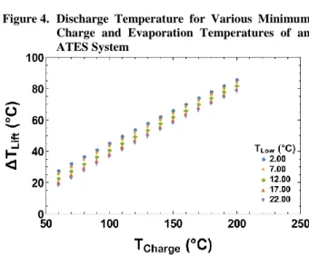
. (1)This equation is derived from the Dubinin-Astakhov isotherm equation by equating the uptake values using the relative pressures for the charging and discharging processes. Aristov stated that this equation can predict the minimum charging temperature with an accuracy of ±1°C, while Muttakin et al. highlighted that the equation is applicable to all IUPAC isotherms with reasonable accuracy [18],[32]. Figure 4 shows the available dis-charge temperatures from an ATES system at various minimum charged temperatures for several evaporation temperatures. The horizontal axis gives the minimum charging temperature for the system at a particular set of discharge and evaporation temperatures assuming con-densation is achieved at the discharge temperature. Thus, the above formulation for the minimum charging temperature is not suitable for energy storage systems.
Temperature lift is another important indicator for ther-mochemical energy storage systems, especially in the design process [33]. Temperature lift is defined as the temperature difference between the outlet and inlet air streams for an open ATES system [34],[35]; it is the temperature difference between the evaporation and the discharge temperatures [18]. However, Deshmukh et al. termed the temperature difference of the heat transfer
Figure 4. Discharge Temperature for Various Minimum Charge and Evaporation Temperatures of an ATES System
Figure 5. Temperature Lift for Various Minimum Charging
and Evaporation Temperatures of an ATES Sys-tem
medium across the adsorber bed as the temperature lift [36]. Due to the finite adsorption sites, it is natural that the temperature lift of ATES systems deteriorates as the adsorbent becomes saturated with the adsorbate. In practice, the temperature lift of an ATES system can be controlled by adjusting the vapor migration or the amount of the adsorbent materials. Aristov formulated the temperature lift for an ATES system based on the minimum charging temperature equation. The tempera-ture lift for a close ATES system is given as [18].
Discharge Discharge
Min,Charge
1
T
T
T
T
. (2)Figure 5 shows the temperature lift values calculated using equation (2) for various minimum charging tem-peratures and evaporation temtem-peratures. In contrast to the discharge temperature, the temperature lift increases with decreasing evaporation temperature.
3.
Energy density and heat of adsorption
often expressed in kWh/m3 of the adsorbent. In ATES systems, the discharge capacity is a function of the amount adsorbed and the heat of adsorption. Thus, the maximum theoretical energy density for a particular ATES system can be calculated as
max
max
d st
E
q w
. (3)Here, qst is the isosteric heat of adsorption, wmax is the maximum equilibrium uptake, and ρ is the apparent density of the adsorbent inclusive of the porosity. Note that qst depends on the amount of equilibrium uptake, which is a function of the temperature and pressure. For working pairs (adsorbent + adsorbate) with decreasing value of the isosteric heat of adsorption following the increase in uptake, the initial qst value from the dis-charge process should be adopted in the theoretical en-ergy density calculations. In fact, for such working pairs, the initial qst is equivalent to qdes [18]. Aristov compiled the maximum theoretical energy density val-ues for 14 types of adsorbents with water as the adsorb-ate. Notable energy density values were 430 kWh/m3 for CaCl2-impregnated silica gel, 230 kWh/m3 for zeo-lite 13X, and 215 kWh/m3 for Fuji RD silica gel [18]. Note that equation (3) is also applicable for open ATES systems.
4.
Selection of working pair
The performance of an ATES depends on the adsorption characteristics of the working pair. In principle, the charging and discharging conditions, and the energy density requirement determines the working pair selec-tion. The energy associated with the ATES systems is the heat of adsorption, and its value is comparable to the value of the latent heat of condensation for physisorp-tion. Thus, a working fluid with a high latent heat of condensation is preferable. Water has a very high latent heat, and it is an environmentally friendly fluid. Hence, many close and all open ATES systems utilize water as the working fluid [9],[37],[38]. Nevertheless, several refrigerants can be applied as the working fluid in an ATES system. Commonly used working fluids and their important thermophysical properties are reported in the work of Maeda et al. [39]. The same authors highlighted the volumetric capacity, the specific volume, and the operating pressure of these refrigerants. Despite pos-sessing an excellent latent heat, water has a rather low volumetric capacity and operating pressure; however, its specific volume is significantly large. Thus, the hard-ware, i.e., the evaporator and the vapor ducts for water-based ATES system, will be large, which in turn might lead to lower overall/system energy density.
Water is a commonly used working fluid, and hence, adsorbent selection is mostly compatible with the ther-mophysical properties of water. Thus, hydrophilic
ad-sorbent materials are majorly selected for energy stor-age systems, especially for low- to medium-temperature applications. Nevertheless, many adsorbents are eligible for ATES systems, and some adsorbents such as acti-vated carbon (particularly maxsorb III) can effectively realize adsorption in the presence of several working fluids [40]–[45]. Adsorbent selection is mainly influ-enced by thermophysical properties such as the specific surface area, the surface energy, heterogeneity, the pore size distribution, and pore diameter. An adsorbent with a large surface area is desirable for effective adsorption per unit mass of the material/system. However, the po-rosity characteristics of the adsorbent determines the adsorption performance for a specific adsorb-ate/fluid/refrigerant [46]. Maeda et al. compiled the po-rosity characteristics of several adsorbent materials, almost 100 adsorbents including MOFs [39], which are not repeated here.
5.
Cycle developments and performance
indicators
, ,
, ,
,
,
,
Dis Ed Dis Ed
Dis St Dis St
T p
d T p st
E
q
T p dw
(4)Here, the energy density is an integrated heat from the initial discharging conditions, i.e., the temperature and pressure at the end of the discharging process. In some cases, the heat of adsorption is assumed constant, and thus, the energy density is calculated considering the uptake difference [47]. For low-pressure adsorption, the adsorbed phase density and nonideality are rather insig-nificant, whereas these factors must be considered in calculating the isosteric heat of adsorption. Lehmann et al. assessed the influence of the adsorbate density on zeolite-based ATES systems [24]. The authors com-pared six different adsorbate phase density models. They concluded that the integral heat of adsorption is not significantly influenced by the adsorbed phase den-sity variation for the practical operation regime. Zeo-lite + water pair was studied while the pair operated under partial vacuum condition, and the contribution by the adsorbed phase density was found to be negligible. Azahar et al. developed improved models for the iso-steric heat of adsorption, addressing the nonideality and the effect of the adsorbed phase density for a wide range of operations [48]. These models are listed in Table 2. Aristov compiled the energy density values of several working pairs based on the charging and discharging conditions [18]. The author stressed that the working energy density (calculated by equation 4 with constant qst) is lower than the theoretical maximum values by a factor of 2–12 (calculated by equation 3).
The energy density of an ATES system is often calcu-lated using the energy balance equations [23,36,49,50]. This approach requires a numerical simulation of the system models or the conduction of experiments. Simi-larly, the temperature lift can be calculated from the energy balance equations, given by Hauer for an open system as [33].
Table 2. Isosteric Heat of Adsorption Models for Various Operation Regimes [48]
Condition Model Eqn. no.
Low pres-sure (par-tial vacu-um)
ln
s s g sdp
p
T
p v
p dT
p
(5)High pres-sure (T < TCrit)
1ln
ln
s s
s
n
g a n
s
dp p
T
p dT p
p v v
p E
T
n R p
(6) High pres-sure (T > TCrit)
1ln
ln s
n
g a n
s
p k
p
p v v
p E
T
n R p
(7)
, , stp air p eff
q
T
c
w c
(8)where ω is the humidity ratio and
c
p eff, is the effective heat capacity of the adsorbent + adsorbate.An ATES system is often assessed by the efficiency term. This is a performance indicator to assess the stor-age. Different authors have assigned different names to this indicator. Nevertheless, it is the ratio of the dis-charged (output) energy to the dis-charged or stored energy. The system efficiency terms are written as follows:
Dis Sys
Chg
Q
Q
(9)Dis Dis
Store
Q
Q
(10)6.
Investigation of open cycles
Open ATES cycles have been studied extensively because of their advantages such as the absence of hardware for the energy input and the rejection of the working fluids. Liu and Nagano numerically studied the performance of an open system where mesoporous composite was employed as the adsorbent. A one-dimensional transient model was developed addressing details on the coupled heat and mass transfer character-istics [51]. Wu et al. conducted a numerical analysis on an open ATES system with CaCl2-impregnated silica gel. A three-dimensional model with energy conserva-tion equaconserva-tions was developed for the adsorber heat ex-changer and the air stream. However, the model did not include the mass conservation [52]. Nagel et al. con-ducted a review on the numerical models and simulation techniques, including the platform for solving the systems of equations [53].
et al. presented the design and characterization of an open ATES system using zeolite 13X [56]. Tatsidjodoung et al. reported the experimental and numerical simula-tion of an open-cycle energy storage system. Zeolite 13X of 40 kg was utilized in the experimental system, while a one-dimensional numerical model was solved and validated with the experimental data [57]. It was reported that some test conditions were able to achieve a temperature lift of 40 °C for 8 h. Note, however, that some of the performance data presented in the work by Johannes et al., including the experimental unit, were repeated again in Ref. [57]. Zhu et al. studied the per-formance of composite silica gel coated with CaCl2 for low-grade heat storage [58]. The experimental results showed that the maximum temperature lift of 30 °C was recorded, while the inlet air stream temperature was about 15 °C. The working charging and discharging times were reported to be 5 and 12 h, respectively, while the durability tests were conducted for more than 500 cycles. Some researchers have introduced innovative designs and concepts for open ATES systems. For example, Mette et al. introduced a cascade system for the efficient regeneration process. An air drying unit (sorption system using adsorbent such as zeolite) was installed upstream, while the bottoming system was the reactor filled with the storage material [38]. The report states that the cascaded design was able to reduce the regeneration temperature to 130 °C from 180 °C at the expense of the additional energy input for the air drying unit. Alebeek et al. experimented on an open ATES system with zeolite 13X adsorber in modular configuration [59]. The re-ported storage efficiency was 76% to 91%. Zhang et al. investigated an open system using activated alumina/ LiCl composite sorbent [60]. A temperature lift above 10 °C was able to achieve more than 7 h, with an energy density value of 191 kWh/m3, while the system effi-ciency was recorded to be 84.5–96.9%. Gaeini et al. developed a seasonal heat storage system for a house-hold scale using zeolite 13X [61]. The targeted capacity was 4 kW, and a relatively high charging temperature (190 °C) was used. The same authors developed a one-dimensional transient model for the energy storage system using zeolite 13X with the emphasis on the dynamic behaviors [62]. They extended their model to a two-dimensional model and validated it using experiments [63]. The pressure drop in the packed bed was modeled using the well-known Ergun equation, in which the Darcy term accounts for the flow velocity and Forchheimer term for the flow inertia [64–66]. The validation of the model was interesting, where the MRI technique was employed to track the moisture content in the bed. Lefebvre et al. developed a one-dimensional transient model to predict the performance of an open ATES system as well as the parametric study for optimal aspect ratio of the column [67]. They discussed several aspects of the breakthrough behavior of an ATES system.
7.
Investigation of close cycles
Open ATES systems seem quite popular in the adsorp-tion-based storage industry. However, close ATES sys-tems are equally adopted for energy storage. Key ad-vantages of a close ATES are as follows: (1) the ability to convert to heat pump applications, (2) zero chance to contaminate the heating space or application, and (3) flexible choice of working pair. As with open systems, numerous reports on close systems are available in the literature. Fernandes et al. conducted a numerical and parametric study using silica gel + water pair [49]. A simple lumped parameter model was employed with some emphasis on the heat transfer characteristics. Us-ing a similar numerical model and workUs-ing pair, Deshmukh et al. studied a close ATES system, includ-ing an exergy analysis [45]. An average temperature lift of 25 °C, energy density of 40 kWh/m3, and exergy effi-ciency of 73% were obtained. Engel et al. simulated a zeolite + water system for seasonal storage using a simi-lar model, i.e., the lumped parameter model [25]. The system introduced the similar concept employed in a solar thermal hot water system for stratification [68–70]. Fernandes et al. simulated a domestic hot water system with an ATES device. The lumped model was used to-gether with component models for the evaporator and the condenser [71]. Duquesne et al. employed a two-dimensional transient model to study a close ATES sys-tem that utilized zeolite as adsorbent [72]. The model was solved using the Gear method-based prediction-correction solver. Dawoud et al. conducted experiments on an ATES system with an adsorber heat exchanger with 13.2 kg of zeolite 13X [73]. The performance of charging, storage, and discharging at various flow rates of the heat transfer fluid was investigated. The maxi-mum storage density was reported to be 144–165 kWh/m3. The temperature lift was as high as 100 °C at the beginning of the discharging phase for low fluid flow, and it was about 32 °C after 1 hour of discharge, while the charging temperature was 150 °C. Schreiber et al. experimentally analyzed the storage performance of a close ATES system using charging temperatures of 175 °C–250 °C [74]. The experimental unit utilized 10 kg of zeolite 13X, and the work focused on the heat losses from the system. The authors highlighted the strong dependency of the heat loss (leak in terms of the energy density) on the charging temperature: 9.5 kWh/m3 at 175 °C and 20.4 kWh/m3 at 250 °C. The same group reported a numerical model using the lumped parameter approach, where the heat leak terms were included [75]. The authors demonstrated the pre-diction accuracy of the calibrated model for various phases of operation.
8.
Conclusions and future prospects
via-bility of renewable energy sources have further in-creased the demand for energy storage. Sorption-based thermal energy storage systems offer some salient fea-tures such as high energy density, low heat leak, ability to store energy almost indefinitely, controllability of the discharge temperature, and environmental friendliness. Nevertheless, ATES systems still suffer from some ma-jor drawbacks such as bulkiness, the requirement of high charging temperature, and the limited choice of adsorbent + adsorbate pairs. Zeolite 13X seems to be the champion of the ATES system, but salt-impregnated silica gel has also gained some acceptance. The perfor-mance, especially the discharge performance in terms of the temperature lift, is a very important parameter. Such performance of an ATES system can be traced back to the “breakthrough curve” of a particular adsorbent + adsorbate pair. Hauer highlighted the nature of the at-tainable discharge temperature using thermal “break-through curves” of zeolite and silica gel [33]. Zeolite exhibited a constant outlet temperature for longer hours before collapsing, while the output temperature from the silica gel became lower after reaching the peak at the beginning of the discharge process. However, silica gel can maintain a higher outlet temperature much longer than zeolite. This classic example stresses the need for custom-tuned materials for specific applications. It can be said that the sorption-based energy storage industry lacks materials exclusively optimized for storage appli-cations. Currently, the industry borrows materials de-veloped for heat pump applications, where the nature of cycle operation, i.e., the kinetics of adsorption/desorption is almost opposite. Material development may be the bottleneck of the ATES technology. The charging tem-perature of these systems seems relatively high, and most of them require heat source above 100 °C. On the other hand, water seems to be stuck as the refrigerant selection, and hence, development and application of innovative refrigerants might elevate the widespread usage of close ATES systems. Nevertheless, research and development is progressing well due to the tremen-dous effort of the scientific community.
Acknowledgements
The authors gratefully acknowledge the Kyushu Univer-sity Program for Leading Graduate School, Green Asia Education Center for the financial support to conduct this study.
References
[1] M.J. Moran, H.N. Shapiro, D.D. Boettner, M.B. Bailey, Fundamentals of Engineering Thermody-namics, 7th ed., Wiley, New York, 2010, p.1024. https://books.google.co.jp/books?id=oyt8iW6B4aUC. [2] Renewable Energy Sources - Energy Explained,
Your Guide To Understanding Energy - Energy In-formation Administration, (n.d.). https://www.eia.
gov/energyexplained/?page=renewable_home (ac-cessed October 19, 2018).
[3] M.S. Whittingham, Science 192 (1976) 1126 LP-1127. http://science.sciencemag.org/content/192/ 4244/1126.abstract.
[4] B. Steffen, Energy Policy. 45 (2012) 420. doi:10.1016/j.enpol.2012.02.052.
[5] Y.-D. Kim, K. Thu, S.-H. Choi, Desalination. 367 (2015) 161. doi:10.1016/j.desal.2015.04.003. [6] Y.-D. Kim, K. Thu, K.C. Ng, Evergreen. 2 (2015)
50.
[7] K.E. N’Tsoukpoe, H. Liu, N. Le Pierrès, L. Luo, Renew. Sustain. Energy Rev. 13 (2009) 2385. doi:10.1016/j.rser.2009.05.008.
[8] L.B. Hyman, Sustainable thermal storage systems: planning, design, and operations, n.d.
[9] G. Alva, L. Liu, X. Huang, G. Fang, Renew. Sus-tain. Energy Rev. 68 (2017) 693. doi:10.1016/ j.rser.2016.10.021.
[10]A.L. Reed, A.P. Novelli, K.L. Doran, S. Ge, N. Lu, J.S. McCartney, Renew. Energy. 126 (2018) 1. doi:10.1016/j.renene.2018.03.019.
[11] J.F. Carneiro, C.R. Matos, S. van Gessel, Renew. Sustain. Energy Rev. 99 (2019) 201. doi:10.1016/j.rser.2018.09.036.
[12] K. Xie, Y.-L. Nian, W.-L. Cheng, Energy. 163 (2018) 1006. doi:10.1016/j.energy.2018.08.189. [13] Y. Jiang, Q. Gao, L. Wang, M. Li, Procedia
Envi-ron. Sci. 12 (2012) 659. doi:10.1016/j.proenv. 2012.01.332.
[14] P. Fleuchaus, B. Godschalk, I. Stober, P. Blum, Renew. Sustain. Energy Rev. 94 (2018) 861–876. doi:10.1016/j.rser.2018.06.057.
[15] B. Ugur, Thermal Energy Storage in Adsorbent Beds, Université d’Ottawa/University of Ottawa, 2013. https://ruor.uottawa.ca/bitstream/10393/ 24362/1/Ugur_Burcu_2013_thesis.pdf.
[16] D. Lefebvre, F.H. Tezel, Renew. Sustain. Energy Rev. 67 (2017) 116. doi:10.1016/j.rser.2016. 08.019.
[17] B. Michel, N. Mazet, S. Mauran, D. Stitou, J. Xu, Energy. 47 (2012) 553–563. doi:10.1016/j.energy. 2012.09.029.
[18] Y.I. Aristov, Futur. Cities Environ. 1 (2015) 10. doi:10.1186/s40984-015-0011-x.
[19] A. Hauer, E. L¨avemann, Open Absorption Sys-tems for Air Conditioning and Thermal Energy Storage, in: H.Ö. Paksoy (Ed.), Therm. Energy Storage Sustain. Energy Consum., Springer Neth-erlands, Dordrecht, 2007: pp. 429–444. doi:10.1007/978-1-4020-5290-3.
[20] L.F. Cabeza, A. Solé, C. Barreneche, Renew. En-ergy. 110 (2017) 3–39. doi:10.1016/j.renene. 2016.09.059.
https://doi.org/10.1016/B978-012598920-6/50002-6. [22] D.M. Ruthven, Principles of adsorption and ad-sorption processes, Wiley, 1984. https://books. google.co.jp/books?id=u7wq21njR3UC.
[23] C. Lehmann, S. Beckert, T. Nonnen, R. Gläser, O. Kolditz, T. Nagel, Water loading lift and heat storage density prediction of adsorption heat storage sys-tems using Dubinin-Polanyi theory—Comparison with experimental results, Appl. Energy. 207 (2017) 274. doi:10.1016/j.apenergy.2017.07.008. [24] C. Lehmann, S. Beckert, R. Gläser, O. Kolditz, T.
Nagel, Appl. Energy. 185 (2017) 1965. doi:10.1016/j.apenergy.2015.10.126.
[25] G. Engel, S. Asenbeck, R. Köll, H. Kerskes, W. Wagner, W. van Helden, J. Energy Storage. 13 (2017) 40. doi:10.1016/J.EST.2017.06.001. [26] K. Lim, J. Che, J. Lee, Appl. Therm. Eng. 110
(2017) 80. doi:10.1016/j.applthermaleng.2016.08.098. [27] M. Muttakin, S. Mitra, K. Thu, K. Ito, B.B. Saha, Int. J. Heat Mass Transf. 122 (2018) 795. doi:10.1016/j.ijheatmasstransfer.2018.01.107. [28] B.B. Saha, I.I. El-Sharkawy, A. Chakraborty, S.
Koyama, N.D. Banker, P. Dutta, M. Prasad, K. Srinivasan, Int. J. Refrig. 29 (2006) 1175. doi:10.1016/j.ijrefrig.2006.01.005.
[29] B.B. Saha, I.I. El-Sharkawy, A. Chakraborty, S. Koyama, K.C. Ng, Study on single-and multi-stage adsorption cooling cycles working at sub and above atmospheric conditions, in: 2008 ASME Int. Mech. Eng. Congr. Expo. IMECE 2008, Boston, MA, 2009: pp. 563–570. doi:10.1115/imece 2008-68616.
[30] Y.I. Aristov, M.M. Tokarev, V.E. Sharonov, Chem. Eng. Sci. 63 (2008) 2907. doi:10.1016/ j.ces.2008.03.011.
[31] R.E. Critoph, Sol. Energy. 41 (1988) 21. http: //www.scopus.com/inward/record.url?eid=2-s2.0-0023863493&partnerID=40&md5=5033b491f067 46306cc9a6cba24b9a68.
[32] M. Muttakin, S. Mitra, K. Thu, K. Ito, B.B. Saha, Int. J. Heat Mass Transf. 122 (2018) 795. doi:10.1016/j.ijheatmasstransfer.2018.01.107. [33] A. Hauer, Sorption theory for thermal energy
stor-age, in: Therm. Energy Storage Sustain. Energy Consum., Springer Netherlands, Dordrecht, 2007: pp. 393–408. doi:10.1007/978-1-4020-5290-3_24. [34] A. Hauer, Evaluation of adsorbent materials for
heat pump and thermal energy storage applications in open systems, in: Adsorption, 2007: pp. 399– 405. doi:10.1007/s10450-007-9054-0.
[35] S.P. Casey, D. Aydin, S. Riffat, J. Elvins, Energy Build. 92 (2015) 128. doi:10.1016/j.enbuild. 2015.01.048.
[36] H. Deshmukh, M.P. Maiya, S. Srinivasa Murthy, Appl. Therm. Eng. 111 (2017) 1640. doi:10.1016/ j.applthermaleng.2016.07.069.
[37] H. Zondag, B. Kikkert, S. Smeding, R. de Boer,
M. Bakker, Appl. Energy. 109 (2013) 360. doi:10.1016/j.apenergy.2013.01.082.
[38] B. Mette, H. Kerskes, H. Drück, H. Müller-Steinhagen, Appl. Energy. 109 (2013) 352. doi:10.1016/j.apenergy.2013.01.087.
[39] S. Maeda, K. Thu, T. Maruyama, T. Miyazaki, S. Maeda, K. Thu, T. Maruyama, T. Miyazaki, Appl. Sci. 8 (2018) 2061. doi:10.3390/APP8112061. [40] K. Thu, Y.-D. Kim, A. Bin Ismil, B.B. Saha, K.C.
Ng, Appl. Therm. Eng. 72 (2014) 200. doi:10.1016/j.applthermaleng.2014.04.076. [41] K. Thu, N. Takeda, T. Miyazaki, B.B. Saha, S.
Koyama, T. Maruyama, S. Maeda, T. Kawamata, Int. J. Refrig. (2018) In Press. doi:10.1016/ j.ijrefrig. 2018.06.009.
[42] M. Ghazy, K. Harby, A.A. Askalany, B.B. Saha, Int. J. Refrig. 70 (2016) 196. doi:10.1016/j.ijrefrig. 2016.01.012.
[43] S. Jribi, T. Miyazaki, B.B. Saha, A. Pal, M.M. Younes, S. Koyama, A. Maalej, Int. J. Heat Mass Transf. 108 (2017) 1941. doi:10.1016/ j.ijheatmasstransfer.2016.12.114.
[44] W.S. Loh, K.A. Rahman, A. Chakraborty, B.B. Saha, Y.S. Choo, B.C. Khoo, K.C. Ng, J. Chem. Eng. Data. 55 (2010) 2840. doi:10.1021/je901011c. [45] A. Bin Ismail, A. Li, K. Thu, K.C. Ng, W. Chun,
Appl. Therm. Eng. 67 (2014) 106. doi:10.1016/j.applthermaleng.2014.02.063. [46] A. Chakraborty, K.C. Leong, K. Thu, B.B. Saha,
K.C. Ng, Appl. Phys. Lett. 98 (2011) 221910. doi:10.1063/1.3592260.
[47] A. Frazzica, Renew. Energy. 110 (2017) 87–94. doi:10.1016/J.RENENE.2016.09.047.
[48] F.H.M. Azahar, S. Mitra, A. Yabushita, A. Harata, B.B. Saha, K. Thu, Appl. Therm. Eng. 143 (2018) 688. doi:10.1016/j.applthermaleng.2018. 07.131. [49] M.S. Fernandes, G.J.V.N. Brites, J.J. Costa, A.R.
Gaspar, V.A.F. Costa, Energy. 102 (2016) 83. doi:10.1016/j.energy.2016.02.014.
[50] D. Dicaire, F.H. Tezel, Int. J. Energy Res. 37 (2013) 1059. doi:10.1002/er.2913.
[51] H. Liu, K. Nagano, Int. J. Heat Mass Transf. 78 (2014) 648. doi:10.1016/j.ijheatmasstrans fer. 2014.07.034.
[52] H. Wu, S. Wang, D. Zhu, Y. Ding, Int. J. Heat Mass Transf. 52 (2009) 5262. doi:10.1016/ j.ijheatmasstransfer.2009.05.016.
[53] T. Nagel, S. Beckert, C. Lehmann, R. Gläser, O. Kolditz, Appl. Energy. 178 (2016) 323. doi:10.1016/j.apenergy.2016.06.051.
[54] P. Gantenbein, S. Brunold, F. Flückiger, U. Frei, Sorbtion materials for application in solar heat en-ergy storage, 2001. http://www.solarenergy.ch/ fileadmin/daten/publ/sorption01.pdf (accessed Oc-tober 19, 2018).
[56] K. Johannes, F. Kuznik, J.-L. Hubert, F. Durier, C. Obrecht, Appl. Energy. 159 (2015) 80. doi:10.1016/ j.apenergy.2015.08.109.
[57] P. Tatsidjodoung, N. Le Pierrès, J. Heintz, D. Lagre, L. Luo, F. Durier, Energy Convers. Manag. 108 (2016) 488. doi:10.1016/j.enconman.2015. 11.011.
[58] D. Zhu, H. Wu, S. Wang, Int. J. Therm. Sci. 45 (2006) 804. doi:10.1016/j.ijthermalsci.2005.10.009. [59] R. van Alebeek, L. Scapino, M.A.J.M. Beving, M.
Gaeini, C.C.M. Rindt, H.A. Zondag, Appl. Therm. Eng. 139 (2018) 325. doi:10.1016/j.applther maleng.2018.04.092.
[60] Y.N. Zhang, R.Z. Wang, T.X. Li, Energy. 141 (2017) 2421. doi:10.1016/j.energy.2017.12.003. [61] M. Gaeini, M.R. Javed, H. Ouwerkerk, H.A.
Zondag, C.C.M. Rindt, Energy Procedia. 135 (2017) 105. doi:10.1016/j.egypro.2017.09.491. [62] M. Gaeini, H.A. Zondag, C.C.M. Rindt, Appl.
Therm. Eng. 102 (2016) 520. doi:10.1016/j.appl thermaleng.2016.03.055.
[63] M. Gaeini, R. Wind, P.A.J. Donkers, H.A. Zondag, C.C.M. Rindt, Int. J. Heat Mass Transf. 113 (2017) 1116. doi:10.1016/j.ijheatmasstransfer.2017.06.034. [64] S. Mitra, M. Muttakin, K. Thu, B.B. Saha, Appl.
Therm. Eng. 133 (2018) 764. doi:10.1016/ j.applthermaleng.2018.01.015.
[65] S. Jribi, T. Miyazaki, B.B. Saha, S. Koyama, S. Maeda, T. Maruyama, Int. J. Refrig. 74 (2017) 345. doi:https://doi.org/10.1016/j.ijrefrig.2016.10.019.
[66] S. Ergun, A.A. Orning, Ind. Eng. Chem. 41 (1949) 1179. doi:10.1021/ie50474a011.
[67] D. Lefebvre, P. Amyot, B. Ugur, F.H. Tezel, Ind. Eng. Chem. Res. 55 (2016) 4760. doi:10.1021/ acs.iecr.5b04767.
[68] Y.-D.D. Kim, K. Thu, N. Ghaffour, K. Choon Ng, J. Memb. Sci. 427 (2013) 345. doi:10.1016/ j.memsci.2012.10.008.
[69] Y.-D. Kim, K. Thu, H.K. Bhatia, C.S. Bhatia, K.C. Ng, Sol. Energy. 86 (2012) 1378. doi:10.1016/ j.solener.2012.01.030.
[70] K.C. Ng, K. Thu, Y. Kim, A. Chakraborty, G. Amy, Desalination. 308 (2013) 161. doi:10.1016/ j.desal.2012.07.030.
[71] M.S. Fernandes, G.J.V.N. Brites, J.J. Costa, A.R. Gaspar, V.A.F. Costa, Energy Convers. Manag. 126 (2016) 548. doi:10.1016/j.enconman.2016. 08.032.
[72] M. Duquesne, J. Toutain, A. Sempey, S. Ginestet, E. Palomo del Barrio, Appl. Therm. Eng. 71 (2014) 469. doi:10.1016/j.applthermaleng.2014. 07.00. [73] B. Dawoud, E.-H. Amer, D.-M. Gross, Int. J.
En-ergy Res. 31 (2007) 135. doi:10.1002/er.1235. [74] H. Schreiber, F. Lanzerath, C. Reinert, C.


![Table 2. Isosteric Heat of Adsorption Models for Various Operation Regimes [48]](https://thumb-us.123doks.com/thumbv2/123dok_us/8074832.2139251/7.892.464.809.147.309/table-isosteric-heat-adsorption-models-various-operation-regimes.webp)
