Solar PV and Battery Storage Integration System
Using Three Level NPC Inverter
P Srinivas1,B Madhusudhan rao2, CH Sireesha3
Asst. Professor, Department of EEE, Raghu Engineering College, Vishakapatnam India1 B.Tech Student, Department of EEE,Raghu Engineering College, Vishakapatnam India.2 B.Tech Student, Department of EEE,Raghu Engineering College, Vishakapatnam India.3
Abstract-In this work, another setup of a three-level neutral point-clipped (NPC) inverter that can incorporate sun powered photovoltaic (PV) with battery stockpiling in a lattice associated framework is proposed. The quality of the proposed topology lies in a novel, expanded unbalance three-level vector tweak strategy that can create the right ac voltage under lopsided dc voltage conditions. This venture shows the plan investigation of the proposed arrangement and the hypothetical structure of the proposed adjustment system. Another control calculation for the proposed framework is additionally introduced keeping in mind the end goal to control the power conveyance between the sun powered PV, battery, and network, which at the same time gives most extreme power point following (MPPT) operation for the sunlight based PV. In this venture fuzzy controller used to lessened the harmonic distortion when contrasted with the PI controller. The viability of the proposed procedure is explored by the recreation of a few situations, including battery accusing and releasing of various levels of sun based light. The reenactment performed in MATLAB/SIMULINK condition.
List Terms—Battery stockpiling, sun powered photovoltaic (PV), space vector tweak (SVM), three-level inverter, fuzzy controller.
INTRODUCTION
Because of the world vitality emergency and ecological issues brought about by ordinary power era, sustainable power sources, for example, photovoltaic (PV) and wind era frameworks are ending up plainly all the more encouraging other options to swap traditional era units for power era. Propelled control electronic frameworks are expected to use and create sustainable power sources. In sun powered PV or wind vitality applications, using greatest power from the source is a standout amongst the most critical elements of the power electronic
furthermore the capacity of controlling the battery charging and releasing. This will bring about lower cost, better effectiveness and expanded adaptability of energy stream control.
II. STRUCTURE OF A THREE-LEVEL INVERTER
AND ITS CAPACITOR VOLTAGE
CONSIDERATIONS
A. Three-Level Inverter
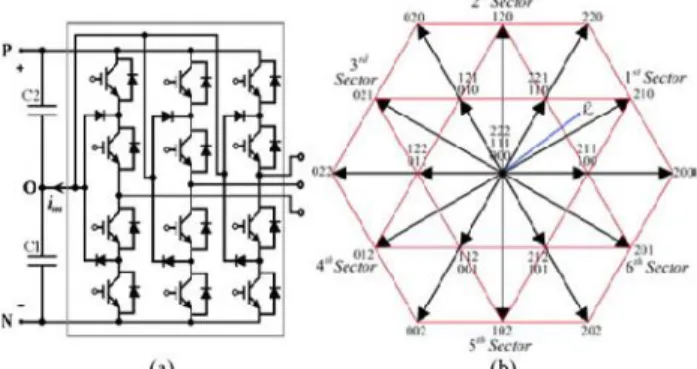
Since the presentation of three-level inverters , they have been generally utilized as a part of a few applications, for example, engine drives, STATCOM, HVDC, pulsewidth balance (PWM) rectifiers, dynamic power channels (APFs), and sustainable power source applications . Fig. 1(a) demonstrates a common place three phase three-level nonpartisan point-cinched (NPC) inverter circuit topology. The converter has two capacitors in the dc side to create the three-level air conditioning side stage voltages. Ordinarily, the capacitor voltages are thought to be adjusted, since it has been accounted for that unbalance capacitor voltages can influence the acside voltages and can create unforeseen conduct on framework parameters, for example, even-symphonious infusion and power swell . A few papers have talked about strategies for adjusting these capacitor voltages in different applications .
Fig. 1. Typical three-level inverter (a) structure of circuit, and (b) three-level inverter space vector diagram for balanced dc-link capacitors .
B. Balanced Capacitors Voltage
Different procedures have been proposed to adjust the capacitor voltages usingmodulation calculations, for example, sinusoidal carrierbased PWM (SPWM) or space vector pulsewidth regulation (SVPWM) . In SPWM applications, the majority of the systems depend on infusing the suitable zero-grouping signal into the
adjustment signs to adjust the dc-interface capacitors . In SVPWM applications, a superior comprehension of the impacts of the exchanging alternatives on the capacitor voltages in the vector space has brought about numerous systems proposed to adjust capacitors voltages in the three-level NPC inverter. These incorporate capacitor adjusting utilizing customary SVPWM, virtual SVPWM (VSVPWM) and their blend . In vector control hypothesis, in a perfect world, the inverter must have the capacity to produce the voltage yield momentarily, taking after the reference vector (_Vref ), created by the control framework. Be that as it may, as a result of the impediment of the switches in the inverter, it is impractical to ensure that any asked for vector can be created; indeed, just a predetermined number of vectors (27 vectors for three-level inverter) can be produced. To defeat such challenges, in any space vector adjustment (SVM) plan, for example, SVPWM and VSVPWM, the reference vector _Vref is created by choosing the fitting accessible vectors in each time span such that the normal of the connected vectors must be equivalent to the reference vector.
Fig. 2. Equivalent circuit and capacitors current with two different short vector. (a) Short vector—100. (b) Short vector—211.
Equation (1) shows the mathematical relation between the timing of the applied vectors and the reference vector
(1)
a normal vector will be numerically created amid this time length. Ti is the comparing time fragment for chose inverter vector _Vi and n is the quantity of connected vectors. By and large, the reference vector is produced by three distinctive vector (n = 3), and (1) can be changed over to three diverse condition with three factors T1, T2 , and T3 to be figured. A few vector PWM procedures introduced in [6], [7], [9]–[11], and [13]–[15] apply comparable method of timing figuring. Fig. 1(b) demonstrates the space vector chart of a three-level inverter for adjusted dc-interface capacitors [6]. It is comprised of 27 exchanging states, from which 19 distinctive voltage vectors can be chosen. The number related with every vector in Fig. 1(b) speaks to the exchanging condition of the inverter stages individually. The voltage vectors can be ordered into five gatherings, in connection to their amplitudes and their consequences for various capacitor voltages from the perspective of the inverter air conditioning side. They are six long vectors (200, 220, 020, 022, 002, and 202), three zero vectors (000, 111, and 222), six medium vectors (210, 120, 021, 012,102, and 201), six upper short vectors (211, 221, 121, 122, 112,and 212), and six lower short vectors (100, 110, 010, 011, 001, and 101). For creating _Vref , when one of the choices (_Vi), is a short vector, then there are two decisions that can be made which can deliver the very same impact on the air conditioner side of the inverter
in the three wire association (if voltages are adjusted). For instance, the short vector "211" will have an indistinguishable impact from "100" on the air conditioner side of the inverter. Nonetheless, this decision will have diverse impact on the dc side, as it will make an alternate dc capacitor be decided for the exchange of energy from or to the air conditioner side, and an alternate capacitor will be charged or released relying upon the exchanging states and the heading of the air conditioner side current. For instance, Fig. 2 demonstrates the association of the capacitors when "100"or "211" is chosen, exhibiting how diverse capacitors are included in the exchange of energy. Capacitor adjusting in most announced three-level NPC inverter applications is accomplished by the correct choice of the short vectors. So as to create the air conditioner side waveform, the vector chart of Fig. 1(b) is utilized, where the dc capacitor voltages are thought to be adjusted.
Fig. 1(b) can then be utilized to decide the fitting vectors to be chosen and to ascertain their relating timing (Ti) for executing the required reference vector in view of the expression given in (1). In spite of the fact that the control framework is attempting to guarantee adjusted capacitor voltages, ought to any unbalance happen amid a transient or a sudden operation, the above strategy will deliver an incorrect air conditioning side waveform which can be not the same as the genuine asked for vector by the control framework. This can bring about the creation of even-sounds, unequal present and unpredicted element
conduct. Notwithstanding, in a few applications, the prerequisite of having adjusted capacitor voltages might be excessively prohibitive. It is conceivable to work with either adjusted or unequal capacitor voltages. The strategy proposed in this paper depends on the flexibility of having equalization or uneven capacitor voltages. In such applications, it is critical to have the capacity to create an exact reference vector in light of (1), independent of whether the capacitor voltages are adjusted or not, to accomplish the coveted destinations of the framework.
C. Unequal Capacitor Voltages
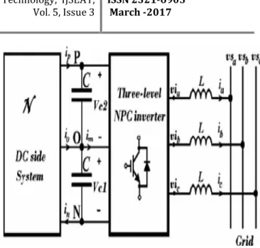
Fig. 3 demonstrates a general structure of a lattice associated threelevel inverter demonstrating the dc and air conditioning sides of the inverter. The
For example, the dc-side framework can be a sun oriented PV, a twist generator with an amending circuit, a battery stockpiling framework or a blend of these frameworks where the dc voltage over every capacitor can be distinctive or level with. One of the fundamental thoughts of this paper is to have a general perspective of the exchanging impacts on a three-wire association of a three-level NPC inverter with a blend of these frameworks on the dc side. Numerically, in a three-wire association of a two-level inverter, the dq0 field, vd, vq , and v0 of the inverter in vector control can be considered as having two degrees of opportunity in the control framework; in light of the fact that the zero grouping voltage, v0 will have no impact on the framework conduct in both the dc and the air conditioner side of the inverter. Be that as it may, in the three-level three-wire application outlined in Fig. 3, with settled vd and vq despite the fact that v0 will have no impact on the air conditioner side conduct, it can be valuable to exploit v0 to give another level of opportunity to control the sharing of the capacitor voltages in the dc transport of the inverter. By doing this, it is currently conceivable to work and control the inverter under both adjusted and unequal capacitor voltages while proceeding to produce the right voltages in the air conditioner side. This component is especially valuable in applications where the two capacitor voltages can be distinctive, for example, while associating two PV modules with various MPPT focuses, or interfacing a PV module over the two capacitors and including battery stockpiling at the midpoint of the two capacitors, or interfacing battery stockpiling to each of the capacitors with the capacity to exchange diverse power from every battery stockpiling.
Fig. 4. Vector diagram in the first sector of Fig. 1(b) showing the change of the vectors using balanced dc and unbalanced dc assuming Vc1 < Vc2.
D. Effect of Unbalanced Capacitor Voltages on the Vector Diagram
In the vector diagram shown in Fig. 1(b), capacitor voltage unbalance causes the short and medium vectors to have different magnitudes and angles compared to the case when the capacitor voltages are balanced. Fig. 4 shows the differences between two cases as highlighted in the first sector of the Fig. 1(b) for VC1 < VC2 . Vector related to the switching state _VI can be calculated from the reference paper[1].
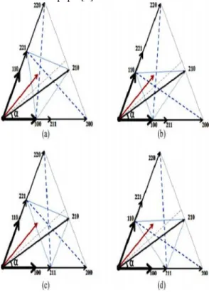
Fig. 5. Different possible vector selection ideas.
Generally, each combine of short vectors is thought to be repetitive, as the determination of any of the short vectors at any
occasion will have a similar impact on the air conditioner side. Notwithstanding, when the two capacitor voltages are distinctive, the short vectors
can't be thought to be excess any more. Accordingly, when h _= 0.5, each extraordinary short vector needs unique planning to
produce the asked for vector in light of (1).
To produce a reference vector in light of (1), distinct blends can be executed. Fig. 5 indicates distinctive conceivable vector choices to create a reference vector (_V∗) in the principal segment in light of the choices of various short vectors. For instance, to produce _V ∗ in view of Fig. 5(a), one of taking after blends can be chosen with legitimate planning in view of (1). The mixes are: (221–210–100), (221–220–100), (221– 200– 100), (221–200–Zero), (000–220–Zero), (220–200– Zero), where "Zero" can be "000" or "111" or "222". This shows there is adaptability in picking the right vector determinations. Albeit these choices with reasonable planning can produce a similar reference vector, they impactsly affect the dc and air conditioning side of the inverter in their prompt conduct. To explore the air conditioner side conduct, the exactness of the produced voltage must be inspected. To the extent the air conditioner side is concerned, in a perfect world the asked for voltage_V∗(t) ought to be precisely and at the same time created in the three periods of the inverter to have the right quick current in the air conditioner side of the framework. Be that as it may, as a result of the confinement of the inverter to create the correct estimation of the asked for voltage in each stage, in the brief span Ts , just the normal estimation of the asked for vector _V∗for the predetermined time window of Ts can be delivered. To research the consistent time conduct of the air conditioner side voltages, the mistake vector _e (t) can be ascertained keeping in mind the end goal to decide how far the created voltage veers off from the asked for vector as takes after:
(2)
where _Vapl(t) is the connected vector at the time "t". This mistake can bring about symphonious current over the impedance associated between the inverter and the framework. On the off chance that this impedance is an inductor then the swell in the inductors current _IrL can be communicated as To determine (13), it is expected that the asked for vector _V ∗ (t) will create sinusoidal current in the inductor, which is regularly satisfactory in the consistent time conduct of the framework. In light of (11) and (12), the outright estimation of blunder E(t) is specifically identified with the extent of the inductors current swell. Albeit in view of (1) and (11), E (Ts) = 0 or the whole of blunders amid the period Ts is zero; yet to lessen the greatness of high recurrence swells, it is critical to limit the mistake at each time moment. To accomplish this, the three closest vectors (TNV) are typically utilized. For instance, in Fig. 5(a), to create the
asked for vector _V ∗, in the TNV technique, the gathering (221, 210, 100, or 211) has all the earmarks of being the best three closest vectors to be picked. Likewise, to reduceE (t), a savvy timing calculation for every vector in the TNV technique has been proposed, for example, partitioning an opportunity to apply every vector into at least two shorter circumstances. Be that as it may, this will have the impact of expanding exchanging misfortunes. Separating by two is normal, adequate arrangement. In addition, decreasing Ts will diminish the blunder E (t) while enhancing the precision of the asked for vector produced by the control framework. Agreeing tothe essential administer of computerized control, exactness of the asked for vector count can be enhanced by decrease of the examining time and the vector figuring time.
F. Choosing Vectors Under Unbalanced DC Voltage Conditions and Their Effects on DC Side of the Inverter
To the extent the dc side is concerned, distinctive vectors effectsly affect the capacitor voltages which rely on upon the
whole of the approaching streams from the dc side and the inverter side. Fig. 3 demonstrates ip, io , and in as dc-side framework streams which are reliant on the dc-dc-side framework circuit topology and capacitor voltages. The streams originating from the inverter are identified with the inverter exchanging and the air conditioner side of inverter ebbs and flows which can be specifically influenced by the executed vectors in the inverter. Choosing distinctive vectors will exchange air conditioning side streams and power diversely to the capacitors .These vector choice conditions are depicted in the paper[1].
III .Fuzzy controller:
Fuzzy rationale has two unique implications. In a limited sense, fuzzy rationale is a coherent framework, which is an augmentation of multivalve rationale. In any case, in a more extensive sense fuzzy rationale (FL) is practically synonymous with the hypothesis of fuzzy sets, a hypothesis which identifies with classes of articles with unsharp limits in which enrollment involves degree. In this point of view, fuzzy rationale in its restricted sense is a branch of fl. Indeed, even in its more thin definition, fuzzy rationale varies both in idea and substance from customary multivalve intelligent frameworks.
wide sense. The essential thoughts hidden FL are clarified obviously and adroitly in Foundations of Fuzzy Logic. What may be included is that the essential idea hidden FL is that of a phonetic variable, that is, a variable whose qualities are words instead of numbers. Essentially, quite a bit of FL might be seen as a strategy for processing with words as opposed to numbers. In spite of the fact that words are innately less exact than numbers, their utilization is nearer to human instinct. Besides, registering with words abuses the resilience for imprecision and in this manner brings down the cost of arrangement.
Another essential idea in FL, which assumes a focal part in a large portion of its applications, is that of a fuzzy if-then run or, just, fuzzy run the show. In spite of the fact that govern based frameworks have a long history of utilization in Artificial Intelligence (AI), what is absent in such frameworks is an instrument for managing fuzzy consequents and fuzzy forerunners. In fuzzy rationale, this component is given by the analytics of fuzzy guidelines. The math of fuzzy principles fills in as a reason for what may be known as the Fuzzy Dependency and Command Language (FDCL).
IV.SIMULATION CIRCUITS AND RESULTS
FIG6: Control system diagram to integrate PV and battery storage.
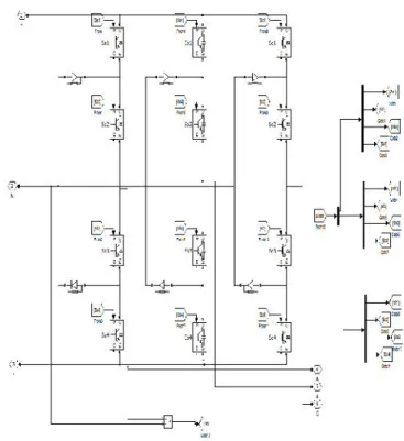
FIG7:NPC INVERTER
A. In the first place Theoretical Scenario
produced by the PV is deficient. After time t = 40 ms, the battery current is about–1.8 A, connoting that the battery is being charged from the additional energy of the PV module. Fig. 8(e) demonstrates the inverter air conditioning side streams, and Fig. 8(f) demonstrates the matrix side streams with a THD under 1.29% due to the LCL channel. The reproduction brings about Fig. 8
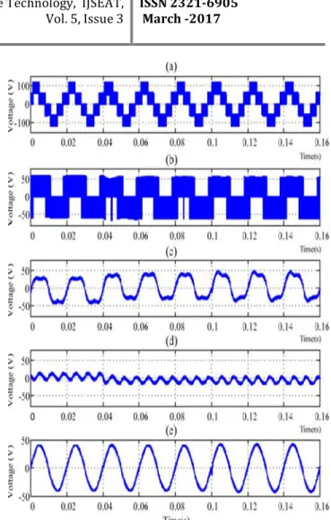
demonstrate that the entire framework delivers a decent element reaction. Fig. 10 demonstrates the inverter waveforms for a similar situation. Fig. 9(a) demonstrates the line-to-line voltage Vab , and Fig. 9(b) demonstrates the stage to midpoint voltage of the inverter Vao . Fig. 9(c) and (e) indicates Vao, Von, and Van after numerical sifting to decide the normal estimation of the PWM waveforms.
Fig. 8. Simulated results for the first scenario. (a) Active power injected to the grid. (b) Reactive power injected to the grid. (c) PV module DC voltage.
(d) Battery current. (e) Inverter AC current. (f) Grid current.
Fig. 9. Simulated inverter waveforms. (a) Vab-Phase to phase inverter voltage. (b) Vao-Inverter phase voltage reference to midpoint. (c) Filtered
Von-Filtered inverter phase voltage reference to midpoint. (d) Filtered Von-Filtered midpoint voltage reference to neutral. (e) Filtered Van-Filtered phase voltage reference to neutral.
B. Second Theoretical Scenario
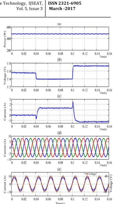
dynamic power. Fig. 10(b) demonstrates that the PV voltage was controlled precisely for various sun oriented illumination qualities to
acquire the important most extreme power from the PV modules. Fig. 10(c) demonstrates that the charging and releasing of the
battery are effectively performed. The battery has supplemented the PV control era to take care of the asked for demand by the network. Fig. 10(d) shows that the nature of the waveforms of the framework side streams are worthy, which means that the right PWM vectors are created by the proposed control system. By utilizing the proposed procedure, the inverter can give a quick transient reaction. Fig. 10(e) demonstrates the a-stage voltage and current of the framework, which are dependably in-stage connoting that the responsive power is zero at all circumstances.
Table1:comparison of PI and FUZZY controller thd for different scenario’s
THD FOR 1ST
SCENARIO 2ND
SCENARIO 3RD
SCENARIO INPUT
VOLTAGE
4.16% 4.13% 4.19%
INPUT CURRENT
3.58% 3.29% 7.66%
THD FOR 1ST
SCENARIO 2ND
SCENARIO 3RD
SCENARIO INPUT
VOLTAGE
0.38% 0.28% 0.30%
INPUT CURRENT
0.20% 0.18% 2.68%
Fig. 10. Simulated results for the second scenario. (a) Active power injected to the grid. (b) PV module DC voltage. (c) Battery currents. (d) Grid side currents. (e) Grid side Phase (a) voltage and its current.
V. CONCLUSION
based PV is accomplished all the while. The adequacy of the proposed topology and control calculation was tried utilizing recreations and results are introduced. The outcomes show that the proposed framework can control air conditioning side current, and battery charging and releasing streams at various levels of sunlight based illumination. In this venture fuzzy controller used to decreased the sounds when contrasted with the PI controller. The reproduction performed in MATLAB/SIMULINK condition.
REFRENCES
[1] Hamid R. Teymour, Student Member, IEEE, Danny Sutanto, Senior Member, IEEE, Kashem M. Muttaqi, Senior Member, IEEE, and P. Ciufo, Senior Member, IEEE” Solar PV and Battery Storage Integration using a New Configuration of a Three-Level NPC Inverter With Advanced Control Strategy” IEEE TRANSACTIONS ON ENERGY CONVERSION, VOL. 29, NO. 2, JUNE 2014.
[2] O. M. Toledo, D. O. Filho, and A. S. A. C. Diniz, “Distributed photovoltaic generation and energy storage systems: A review,”Renewable
Sustainable Energy Rev., vol. 14, no. 1, pp. 506–511, 2010.
[3] M. Bragard, N. Soltau, S. Thomas, and R. W. De Doncker, “The balance of renewable sources and user demands in grids: Power electronics for
modular battery energy storage systems,” IEEE Trans. Power Electron., vol. 25, no. 12, pp. 3049–3056, Dec. 2010.
[4] A. Yazdani and P. P. Dash, “A control methodology and characterization of dynamics for a photovoltaic (PV) system interfaced with a distribution
network,” IEEE Trans. Power Del., vol. 24, no. 3, pp. 1538–1551, Jul. 2009.
[5] A. Yazdani, A. R. Di Fazio, H. Ghoddami, M. Russo, M. Kazerani, J. Jatskevich, K. Strunz, S. Leva, and J. A. Martinez, “Modeling guidelines
and a benchmark for power system simulation studies of three-phase single-stage photovoltaic systems,” IEEE Trans. Power Del., vol. 26, no. 2,
pp. 1247–1264, Apr. 2011.
[6] M. A. Abdullah, A. H. M. Yatim, C. W. Tan, and R. Saidur, “A review of maximum power point tracking algorithms for wind energy systems,”
Renewable Sustainable Energy Rev., vol. 16, no. 5, pp. 3220–3227, Jun. 2012. TEYMOUR et al.: SOLAR PV AND BATTERY STORAGE INTEGRATION USING A NEW CONFIGURATION 365
[7] S. Burusteta, J. Pou, S. Ceballos, I. Marino, and J. A. Alzola, “Capacitor voltage balance limits in a multilevel-converter-based energy storage
system,” inProc. 14th Eur. Conf. Power Electron. Appl., Aug./Sep. 2011, pp. 1–9.
[8] L. Xinchun, Shan Gao, J. Li, H. Lei, and Y. Kang, “A new control strategy to balance neutral-point voltage in three-level NPC inverter,” inProc.
IEEE 8th Int.Conf. Power Electron.ECCEAsia, May/Jun. 2011, pp. 2593–2597.
[9] J. Rodriguez, S. Bernet, P. K. Steimer, and I. E. Lizama, “A survey on neutral-point-clamped inverters,” IEEE Trans. Ind. Electron., vol. 57,
no. 7, pp. 2219–2230, Jul. 2010.
[10] A. Lewicki, Z. Krzeminski, and H. Abu-Rub, “Space-vector pulsewidth modulation for three-level npc converter with the neutral point voltage
control,”IEEE Trans. Ind. Electron., vol. 58, no. 11, pp. 5076–5086, Nov. 2011.
Authors:
P Srinivas currently working as a Asst. Professor, in Department of EEE, Raghu Engineering College, Vishakapatnam India.He completed his M.TECH in the area of advanced power systems in JNTUK.His interested areas are power quality and power system analysis
.
B Madhusudhan Rao pursuing B.TECH in Raghu Engg.college ,vishakapatnam. His interested areas are power systems and power electronics.