TECHNICAL UNIVERSITY OF CLUJ-NAPOCA
ACTA TECHNICA NAPOCENSIS
Series: Applied Mathematics, Mechanics, and Engineering Vol. 60, Issue IV, November, 2017
THE ANALYSIS OF GEOMETRICAL ERRORS BASED ON POLYNOMIAL
INTERPOLATION FUNCTIONS FOR A 5 D.O.F. SERIAL ROBOT
Adina - Veronica CRIȘAN, Florina - Maria ȘERDEAN, Radu MORARIU - GLIGOR
Abstract: The paper deals with the experimental and numerical modeling of geometrical errors in case of a 5R serial
robot (Fanuc LR Mate 100iB), implemented in a working process which consists of manipulating different parts from the workspace, for the purpose of processing them. For each point from the working space covered by the end effector and included in the analysis, have been collected from the teach – pendant of the robot a series of data regarding the coordinates of the tool center point, the orientation angles and the value of the generalized coordinates for all driving joints. The trajectory errors that affect the optimal operation of the robot have been determined based on polynomial interpolation functions of 4 – 3 – 4 type.
Key words: serial robot, dynamic modeling, geometrical errors, polynomial interpolation functions.
1. INTRODUCTION
Robotic industrial applications have experienced a continuous development since the first robotic devices have emerged, to nowadays. These applications also include traditional manufacturing processes but of the late years they have extended to other interesting areas such as medical applications or entertaining industry. Thus, new capabilities have emerged, like robotic surgery where both the precision and the repeatability of robots are essential.
Applications based on manufacturing processes have to meet some requirements which undergo changes depending on the product type and quality level, thus imposing robots to adapt to a continuous changing environment. The performances of a robot can only be evaluated from the perspective of the applications for which it was designed or in which it is going to be used [3].
A very important technological barrier that has affected for a long period of time the robotic industry, was the problem of reducing or even eliminating the error that occurs between the work tool reference system and the reference system attached to the work piece. Forwards are going to be analyzed some aspects regarding the components of a robotic
cell, the reference systems attached, and the errors that these reference systems are introducing into the system [1]. In Fig.1 is represented a simple robotized cell and the systems attached to it.
Fig.1. Reference systems for a robotized cell
The locating (position and orientation) of the work piece, is usually defined with respect to the clamping or securing devices, conveyor belts or rotating platforms, from the robot workspace. From mathematically point of view, the locating of the work piece is represented by a transformation that takes place between the reference system attached to the work piece and the system attached to robotic cell. The work piece introduces a series of errors, mostly due to position deviations or deformations that occur during the work process [4], [5].
The errors that occur between the reference systems attached to the work tool and the work
Robot
TCP S
( )
Working space robotic cell
FL S
R S
P S
S P S−
C R S
Working piece Robot flange
piece’s reference system is largely due to the differences that occur between the analytical modeling of the robot and that of the controller, factors such as machining errors and mounting, influencing in a great deal this type of error [2]. In order to minimize this type of errors, have been provided different solutions that just offered a partial resolution to this problem, such as designing and building of more rigid structures or rigid fasteners characterized by good repeatability, or improving the manufacturing processes where the robot is used. Unfortunately, most of the solutions proved to be often unfeasible due to the difficult requirements or just because the costs involved were too high. [6]
In this paper are presented some aspects regarding the numerical and experimental modeling of locating errors, based on the transfer matrix of geometrical errors [8], in case of a five degrees of freedom mechanical robot strucure (Fanuc LR Mate 100iB) as well as the analysis of a working process which consists of manipulating different parts in the robot workspace for the purpose of processing them. The active component of the working process is the Fanuc LR Mate 100iB articulated robot whose performance characteristics are detailed in the following paragraph.
2. DESCRIPTION OF WORKING PROCESS
The industrial robot, Fanuc LR Mate 100iB that was integrated in the working process, has been specially designed to ensure operation in the industrial environment but it can be successfully used for didactic purposes in various laboratory applications. The Fanuc robot has a modular construction, the connection between the four basic modules being provided by means of the five rotation joints, driven by DC motors.
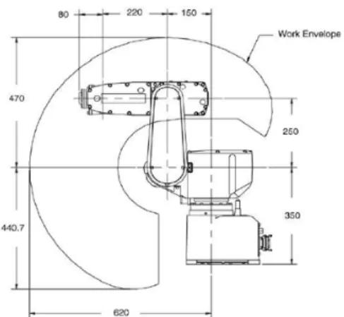
In Fig.2 is represented the mechanical structure of the Fanuc LR Mate 100iB robot, being highlighted the nominal dimensions and the work space / volume described by the robot in motion. Also, due to the sealed construction, encapsulated bearings, brushless servomotors and harmonic reducers mounted on all 5 axes, the structure has the advantage of minimizing maintenance, thus increasing operating time.
As a safety measure, the robot is equipped with fail-safe brakes mounted on axles 2 and 3 to enable emergency stopping when any object from the workspace is hit. The robot is recommended for use in dirty environments due to package IP54 that offers protection against dust and different types of liquids.
Fig. 2 Nominal dimensions and working envelope of Fanuc LR Mate 100iB
The mechanical structure of the robot is designed to be able to perform loading and unloading operations of machine tools, high precision manipulation operations, and when a work tool is attached to the end effector, it can be used for complex welding operations requiring high level of precision.
There is also a version of Fanuc LR Mate 100iB robot which is used predominantly in assembly applications that require operation in clean environments at high speeds and precision (assembly process of data acquisition boards, microprocessors, etc.). The robot used in the analyzed work process has a number of advantages that recommend it for use in most industrial applications.
Fig. 3 The mechanical structure of the robot
One of its main advantages is the relatively small footprint: 380 x 470 x 320 (mm) which facilitates the installation of this robot structure in the immediate proximity of machine tools.
Rotation J1 around zaxis
Rotation J2 around yaxis
Rotations J3, J4 around yaxis
In Fig. 3 is represented the mechanical structure of the Fanuc type robot, the position of each driving joint and the axis around which the rotation is performed.
The Fanuc LR Mate 100iB robot structure has been integrated into a complex technological process involving the cooperation with a mobile platform [K05].
In this paper it is presented only the first phase of a complex working process in which the robot is programmed to start from an initial configuration and then to bring the blank in a position that allows it to be processed. In the next phases, the processed part is manipulated from the manufacturing centre and positioned on the mobile platform from where it is transported to the warehouse. Another blank is brought in by the mobile robot and the process is resumed from the beginning.
Hereinafter are presented the work sequences considered in the analysis of the geometrical errors, starting with the initial configuration (Fig. 4) according to:
Table 1 Initial Configuration
n x
p pyn pnz αnz
n y
β n
x γ
[ mm ] [ º ]
595 0 250 0 0 0
The first phase of the work process that is going to be analyzed in the following consists of 3 different sequences (Fig.4 and Fig.5) which at their turn are divided into three trajectory segments, two end segments and an intermediate segment thus resulting into 9 configurations.
The study on robot movement in the working space was based on the position and orientation data from every driving joint which were provided by the robot teach - pendant. For each point covered by end effector in the working space and included in the analysis, a set of data comprising the coordinates of the tool center point, the orientation angles, as well as the generalized coordinates from each robot joint were collected from the robot teach- pendant.
The greater the number of intermediate segments in which the trajectory is divided, the higher is the accuracy.
The purpose of the following analysis is to determine the influence of geometric errors on the accuracy of the motion trajectory in case of a Fanuc serial robot.
Fig.4 The robot in the initial configuration and Sequence 1
Fig.5 Sequence 2 (left side) and Sequence 3 (right side)
The mechanical structures of the serial and the mobile robot, as well as the entire working space were modeled using Solid Works application. This allowed the gathering of accurate information regarding the nominal values of the generalized coordinates corresponding to the points that the robot had to go through during the working process.
The real value of the generalized coordinates (comprising errors) was collected from the robot teach-pendant.
Table 2
k
=
1
→
3 Input geometrical errors
[ mm ] [ º ]
x
p
∆ ∆py ∆pz ∆αz ∆βy ∆γx
1
0 0 0 0 0 0
0.45 0 -0.85 0 0 0
-0.64 0 -1.02 0 0 0
-0.21 0 -0.98 0 0 0
2
-0.21 0 -0.98 0 0 0
-1.15 0 -1.02 0 0 0
0.27 0 -1.13 0 0 0
0.73 0 -0.94 0 0 0
3
0.73 0 -0.94 0 0 0
-1.27 0 -1.32 0 0 0
-0.94 0 -1.12 0 0 0
0.22 0 -1.03 0 0 0
Using the informations provided by the robot teach-pendant were collected the real values (affected by errors) as well as the nominal values of the generalized coordinates from every driving joint, corresponding to all 9 robot configurations subjected to analysis.
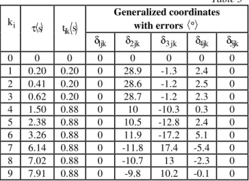
In the table bellow are presented the values affected by errors of the generalized coordinates, where kirepresents the number of analyzed configurations, τ the real time and
ik
t the time interval in which the robot reaches the required configuration.
Table 3
i k
s
τ t sik
Generalized coordinates with errors °
1jk
δ δ2jk δ3 jk δ4jk δ5jk
0 0 0 0 0 0 0 0
1 0.20 0.20 0 28.9 -1.3 2.4 0 2 0.41 0.20 0 28.6 -1.2 2.5 0 3 0.62 0.20 0 28.7 -1.2 2.3 0 4 1.50 0.88 0 10 -10.3 0.3 0 5 2.38 0.88 0 10.5 -12.8 2.4 0 6 3.26 0.88 0 11.9 -17.2 5.1 0 7 6.14 0.88 0 -11.8 17.4 -5.4 0 8 7.02 0.88 0 -10.7 13 -2.3 0 9 7.91 0.88 0 -9.8 10.2 -0.1 0
The generation of motion trajectory is done using polynomial interpolation functions, the degree of which depends on the restrictions imposed by the technological process in which the robot is implemented. For trajectories of type 4-3-4, the end segments are interpolated with polynomials of 4th degree and for the intermediate segments are used polynomials of 3rd degree (cubic spline functions).
3. THE MODELING OF GEOMETRICAL ERRORS USING THE 4-3-4 POLYNOMIAL INTERPOLATION FUNCTIONS
Next, the working process, involving the Fanuc LR Mate 100iB is modeled using 4-3-4 polynomial interpolation functions, thus obtaining the real interpolation functions for the error case, based on which is represented the time variation of generalized coordinate errors. The trajectory errors that affect the operation of the robot in the working space were determined using polynomial interpolation functions.
According to the theoretical aspects from the technical literature [7], [8], from this analysis will result two important groups of polynomial coefficients. In the first group are included the polynomial coefficients that are obtained directly by applying the initial conditions in each point of the motion trajectory.
The second group of polynomial coefficients is obtained from a linear and non-homogeneous system, which is also the result of applying the continuity conditions at all intermediate points of the motion trajectory. The latter were determined by using a simulation program,
SimMecRob [6], [8], which allows the numeric
and graphical solving of the generalized matrices, of nominal kinematics and dynamics allowing the determination of errors for any structure of serial robot.
By using this simulator SimMecRob were established the nominal and real values of the polynomial coefficients for all 9 robot configurations subjected to study.
Considering the polynomial coefficients previously determined, the expressions for normalized polynomial interpolation functions can be written in the following form:
( )
4 3 2ijk ijk4 k ijk3 ijk2 ijk1 ijk0
q t =a ⋅T ⋅∆ +a ⋅T +a ⋅T +a ⋅ +T a ; (1)
( )
(
)
ijk 3 2
ijk4 k ijk3 ijk2 ijk1
k k
q t 1
4 a T 3 a T 2 a T a
t =t ⋅ ⋅ ⋅∆ + ⋅ ⋅ + ⋅ ⋅ +
&
; (2)
( )
(
)
ijk 2
ijk4 k ijk3 ijk2
2 2
k k
q t 1
12 a T 6 a T 2 a
t t
= ⋅ ⋅ ⋅ ∆ + ⋅ ⋅ + ⋅
&&
;(3)
where:
.
t; k the first and intermediate segment
T
t ; k the last segment
−
=
−
k
1; k the end segment
0; k intermediate segment
−
∆ =
−
.
Substituting in the expressions for the polynomial interpolation functions the variable
k 1
k
t t
− τ − τ
= , will result the real polynomial
interpolation functions.
between the functions real ones that characterize nominal configurations and those that are including errors (Tables 4, 5, 6). The polynomial interpolation functions that characterize the errors from the active driving joints are presented in the following.
Table 4
S
eg
m
en
t
k
=
1
→
9
Polynomial interpolation functions for errors in the driving joint q2
1 66.23054663·τ −3 216.9079517·τ4 2 39.3382·τ −3 39.5249·τ +2 12.125·τ −0.976 3 −41.5607·τ +3 61.4369·τ −2 29.879·τ +4.85 4 −1.64826·τ +3 6.53339·τ −2 7.97513·τ +2.86299 5 0.429981τ −3 2.84969·τ +2 6.14615·τ −4.22106 6 0.0630841· 4 0.798042· 3 3.78172· 2
7.95546· 6.30802
τ − τ + τ
− τ +
−
7 0.501352· 4 11.1223· 3 92.2948· 2 339.606· 467.584
− τ + τ − τ
+ τ −
+
8 0.716635·τ −3 14.077·τ +2 91.7686·τ −198.489 9 0.727127· 4 22.1179· 3 251.889· 2
1272.71· 2406.95
τ − τ + τ
− τ +
−
Based on the polynomial functions presented in Table 4, is represented the time variation of the driving joint q2 as well as its error, for the considered phase of the work process.
Fig.6 The variation in time of q2 generalized coordinate and of its error for the first phase
Table 5
S
eg
m
en
t
k
=
1
→
9
Polynomial interpolation functions for errors in the driving joint q 3
1 115.3993·τ −4 37.33802·τ3
2 −14.7796·τ +3 15.8561·τ −2 5.3702·τ +0.444 3 10.0012·τ −3 15.0472·τ +2 7.4759·τ −1.336 4 0.601096·τ −3 2.22685·τ +2 2.45606·τ −0.911541
S
eg
m
en
t
k
=
1
→
9
Polynomial interpolation functions for errors in the driving joint q 3
5 −0.239853·τ +3 1.56995·τ −2 3.25918·τ +1.95669
6 0.00166010· 4 0.0382695· 3 0.481381· 2 1.68840· 2.0016
τ + τ − τ
+ τ −
+
7 0.401746 4 9.05168· 3 76.1555· 2 283.709· 395.137
− τ + τ − τ
+ τ −
+
8 3 2
0.131626·τ −2.74719τ +19.1238·τ −44.263 9 0.0298819· 4 0.905951· 3 10.2803· 2
51.7395· 97.5767
τ − τ + τ
− τ +
−
The data contained in Table 5 is very useful in establishing the time variation of the generalized coordinate q3and of its error.
Fig.7 The variation in time of q3 generalized coordinate and of its error for the for the first phase
Table 6
S
eg
m
en
t
k
=
1
→
9
Polynomial interpolation functions for errors in the driving joint q4
1 32.58961836·τ −4 6.778629772·τ3 2 −15.7797τ +3 14.0532·τ −2 3.504·τ +0.263 3 25.5587·τ −3 37.5833·τ +2 17.98·τ −2.716 4 1.02230·τ −3 3.84510·τ +2 4.53411·τ −1.50047 5 −19.6328·τ +3 98.5210·τ −2 173.940·τ +105.653 6 55.6617· 4 645.19· 3 2759.02· 2
5131.95· 3475.21
− τ + τ − τ +
+ τ −
7 0.174311· 4 3.91214· 3 32.8018· 2 121.828· 169.073
τ − τ + τ
− τ +
−
8 0.0438756·τ −3 0.635278·τ +2 2.7510·τ −3.25741
9 0.42498· 4 12.8100· 3 144.438 2 721.850· 1348.82 τ − τ + ⋅ τ
− τ +
−
Fig.8 The variation in time of q4 generalized coordinate
and of its error for the first phase
4. CONCLUSIONS
The error that occurs between the reference system attached to the work tool and of the working part is the effect of the differences that occur between the analytical modeling of the robot and that of the controller, factors such as machining or mounting errors having a great influence on this type of error. In order to highlight these errors, it was analyzed the performance of a Fanuc LR Mate 100iB five-degree serial robot. For this purpose, the robot has been implemented in a working process.
Thus, the kinematic command functions for the generalized coordinates and their errors could be established, by applying the polynomial interpolation functions of type 4-3-4. By using SimMecRob Simulator functions, have been obtained the expressions of polynomial interpolation functions for both, nominal generalized coordinates and real generalized coordinates (comprising errors).
In the final part of this paper there are presented in a graphical form the variation in real time of the generalized coordinate errors that characterize the studied process and which were obtained using the polynomial functions.
5. REFERENCES
[1]Borm, J.H, Meng, C.H., Determination of Optimal Measurement Configurations for Robot Calibration Basesd on Observability Measure. Int. Journal of Robotics Research, Vol.10 No.1, 1991.
[2]Craig, J.J., Introduction to Robotics, Addison-Wesley, Amsterdam, 1989.
[3]Gong, C., Yuan, J., Non Geometric Error Identification and Compensation for Robotic System, Int. J Mach. Tools Manuf., 2000. [4]Kurfess T.R., Robotics and automation
handbook, Edited by Thomas R. Kurfess, CRC Press, 2005.
[5]Kacso, K., Contribuții privind modelarea și simularea roboților mobili și roboților cu structură serială, teză de doctorat, febr., 2011. [6]Negrean, I., et al, Robotics - Kinematic and
Dynamic Modelling, Editura Didactică şi
Pedagogică R.A., ISBN 973-30-5958-7,
Bucharest, 1998.
[7]Negrean, I., Albeţel, D.G., The Generalized Matrices in the Robot Accuracy, Conferinţa
ştiintifică Internaţională TMCR 2003, Chişinău, Vol.3, ISBN 9975-9748-3-X, 2003.
[8]Negrean, I, Duca, A.V, Negrean, D.C., K. Kacso, Mecanica avansată în robotică, Editura UT Press, Cluj-Napoca, ISBN 978-973-662-420-9, 2008.
Analiza erorilor geometrice bazate pe functii polinomoiale pentru un robot serial cu 5 GDL
Lucrarea are drept scop modelarea experimentală și numerică a erorilor geometrice în cazul unui robot serial 5R (Fanuc LR Mate 100iB), implementat într-un proces de lucru care constă din manipularea unor piese din spațiul de lucru, în scopul prelucrării lor. Pentru fiecare punct din spațiul de lucru acoperit de efectorul final și inclus în analiză, au fost colectate prin intermediul teach-pendantului robotului o serie de date referitoare la coordonatele punctului caracteristic al efectorului final, unghiurile de orientare și valoarea coordonatelor generalizate pentru toate cuplele active ale robotului. Erorile de traiectorie care afectează funcționarea optimă a robotului au fost determinate prin aplicarea funcțiilor de interpolare polinomiale de tip 4 - 3 - 4.
Adina Veronica CRIȘAN, PhD, Lecturer, Technical University of Cluj - Napoca, Dept. of Mechanical Systems Engineering, [email protected], 0264/401 750, 0741 237 025.
Florina Maria ȘERDEAN, PhD, Lecturer, Technical University of Cluj - Napoca, Department of Mechanical Systems Engineering, [email protected], 0746 035 549.
![Table 1 Initial Configuration n x p p y n p nz α nz β n y γ nx [ mm ] [ º ] 595 0 250 0 0 0](https://thumb-us.123doks.com/thumbv2/123dok_us/7999028.2120802/3.892.481.834.224.352/table-initial-configuration-β-γ-nx-mm-º.webp)