Table of Contents
SECTION 1
Overview
... 5
Document Conventions...5
Audio Processor Features...6
DFR22 Software Minimum Requirements...7
Interface Modes...7
Design Mode... 7
Live Mode... 7
Preview Mode... 7
The Main Window...8
Title Bar... 8
Control Bar... 9
Signal Flow Diagram... 9
Status Bar... 11
The “Processor Toolbox”...11
SECTION 2
Start-up Guide
... 12
Install the Software...12
Establish Communication with the Device...12
Configure External Control...13
Create a Preset Template...14
Manage Your Presets...15
Establish Security...16
SECTION 3
Creating a Preset
... 17
Signal Flow Configuration...17
Gain Structure... 17
Muting Channels... 18
Labeling Inputs and Outputs... 18
Signal Routing... 19
Naming a Preset... 20
Processor Configuration... 20
Processor Types... 20
Adding Modular Processors... 21
Copy and Paste... 23
Deleting Processors from Slots... 23
Linking... 24
Bypassing... 25
Managing DSP Resources... 25
Default Presets...27
Preset One – [Dual Mono]... 27
Preset two – [Stereo]... 27
Table of Contents
SECTION 4
Preset and Device Management ...
28
Preset Files...28
Saving a New Preset to Your Computer ... 28
Revising Preset Files... 28
Device Presets...29
Store a Preset in the Device... 29
Rename a Preset... 30
Delete a Preset... 30
Device Backup...31
The Devices Menu...32
SECTION 5
Processor Features
... 33
Faders...33
Saving and Recalling Settings...34
Naming Processor Windows...34
Snapshots...35
Importing ASCII Files...36
Saving Files in ASCII Format... 36
Import Controls and Features... 37
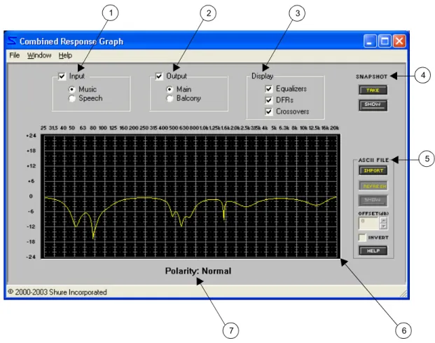
Combined Response Graph... 38
SECTION 6
Fixed Processors ...
40
Input Gain...40
Matrix Mixer...42
Output Gain...44
SECTION 7
Modular Processors
... 46
Automatic Gain Control (AGC)...46
Compressor/Limiter...50
Soft Knee Processors... 53
Stereo Processors... 54
Crossover/Splitter/Subwoofer...55
Keyboard Controls... 59
Cut and Shelf Filters...60
Fine Tuning Parameters... 62
Copy and Paste... 63
Delay...64
Digital Feedback Reducer (DFR) ... 66
Basic DFR Setup... 69
Filter Allocation... 69
Table of Contents
Ducker...73
Gate/Downward Expander ... 76
Graphic Equalizer...79
Parametric Equalizer...82
Working with Filters... 85
SECTION 8
Control Pins
... 87
Control Pins Overview...87
Control Pins Tutorial...88
The “Control Pins” Window...91
“Pin Configuration”...91
Preset Encoding Settings... 92
Connection Blocks... 93
“Processor Mapping”...95
Mapping Hardware Controls to Input and Output Channels ... 95
Gain Control Settings... 95
Creating a Processor Map... 96
SECTION 9
Security
... 98
Front Panel Lockout...98
Restricting Computer Access...98
Establishing Device Security... 99
Changing Device Security... 99
Individual Processor Security... 101
SECTION 10
Printing Reports
... 102
Device Information...102
Preset Information and Current Preset Information... 103
Processor Information...103
Report Samples...104
SECTION 11
Appendix A: Binary Encoding Tables
...108
SECTION 12
Appendix B: DSP Usage Per Processor
... 110
SECTION 13
Appendix C: File Extensions
... 111
SECTION 14
Appendix D: Troubleshooting Guide
... 112
Communication fails between the computer and the DFR22:... 112
DFR22 preset indicator displays the letter “E” followed by a number:... 112
Unable to switch device presets from the computer:... 113
SECTION 1
Overview
The DFR22 Audio Processor with Feedback Reduction is a 2-input, 2-output digital audio processor. It is ideal for installed sound reinforcement applications, such as houses of worship, theaters, and meeting facilities. The DFR22 is also a power-ful setup tool in live music applications. Using the DFR22's drag-and-drop graphical user interface, processors can be placed anywhere in the signal path. The 2-by-2 matrix mixer allows either or both inputs to be routed to either or both out-puts, with additional controls for levels and polarity.
Document Conventions
The DFR22 software interface is so intuitive and user friendly that you may be tempted to skip reading this document and immediately begin programming the unit. Before you do, however, you should at least skim this overview, then thoroughly read the Start-up Guide on page 12. Any questions you have about the software will be answered in the following sections of the document.
How this Guide is Organized
• Overview . . . .Introduces the main features of the Audio Processor, and discusses the operating modes of the interface and the main window.
• Start-Up Guide. . . .Covers the basic steps you need to follow with the software to set up the Audio Pro-cessor for an installation.
• Creating a Preset. . . . .Covers the elements of a DFR22 signal flow configuration, such as the gain structure of the device, routing signal from inputs to outputs, adding processors to the signal path, and working with them in the main window.
• Preset and Device Management . Explains how to save a preset to the computer, store it in the DFR22, and backup the contents of the device to computer. It also covers the features of the [Device] menu.
• Processor Features. . .Covers the features that are common among many of the signal processor modules, such as fader controls, taking snapshots of parameter settings, and saving and recalling settings to and from the computer.
• Fixed Processors . . . .Explains the features of the input and output gain blocks and the matrix mixer. • Modular Processors . .Explains the features specific to each of the drag-and-drop signal processors. • Control Pins. . . .Describes the internal architecture of the Audio Processor's external device control
feature and explains how to configure the DFR22's control pins with the software once the external hardware has been connected.
• Security . . . .Covers the security features of the Audio Processor that restrict user access to device settings and front panel controls.
Notation Conventions
• Text in [brackets]. . . Denotes literal text in the software interface, such as control labels, buttons, or menu commands.
• Keyboard keys. . . .Such as Shift,Ctrl, and Esc appear in bold face. When you need to press key combi-nations, or keys in combination with a mouse click, the plus sign is used like this: Ctrl + Click.
Audio Processor Features
Audio Processor Features
The DFR22 is a 2-input, 2-output digital audio processor with a software interface and simple front panel controls, which stores 16 presets. It provides 24-bit conversion, 48khz sampling and a minimum dynamic range of 100dB.
Drag and Drop Software Interface
The computer interface to the Audio Processor mimics the functional block diagrams used in sound system design. This makes the software incredibly easy to learn, because the interface seems immediately familiar to sound pro-fessionals. Presets can be built and edited entirely by clicking, dragging, and dropping with the mouse. You can configure the signal path with any combination of drag and drop signal processors.
Modular Signal Processors
Each signal processing module is encapsulated in a graphic block that you can manipulate with the mouse. After you place a processor in the signal flow diagram you can access the processor settings by double-clicking on the block to open its parameter window. Settings can be saved and recalled from the computer, and copied between similar modules. Processor settings can also be synchronized via the link feature. The DFR22 Audio Processor includes the following selection of signal processor modules.
External Device Control
After it is installed and programmed with the software interface, end users can control the DFR22 with a computer or an AMX or Crestron controller. In addition, the control pins on the rear panel can be connected to external hard-ware, so that the DFR22 will respond to contact closures, potentiometers, and wall-plate switches.
Security
The security feature gives the installer peace of mind that the device cannot be tampered with after it is installed. User access can be completely restricted so that the user cannot change any settings, or use the front panel con-trols. They will only be able to view the settings of the current preset from the software interface. End-user control can also be customized to allow access to certain settings, and not to others.
•
Shure’s Powerful Digital Feedback Reducer, in both Mono and Stereo Processors•
Automatic Gain Control and•
Combining and Non-Combining 10- and 30-Band Graphic Equalizers•
3- to 10-Band Parametric Equalizers with Cut and Shelf Filters•
2-Way Crossover and Splitter•
Subwoofer•
Gate/Downward Expander•
Mono and Stereo Compressor/Limiter with Soft-Knee Option•
DuckerDFR22 Software Minimum Requirements
DFR22 Software Minimum Requirements
The DFR22 Software Version 3 requires a PC with the following specifications to function properly:
•
20 MB available hard disk space•
CD-ROM drive•
VGA monitor with 640 x 480/256 color, or higher resolution•
Mouse or other pointing deviceProcessor speed and memory requirements vary, depending on the version of Windows and number of background applica-tions you are running. Operating the DFR22 software simultaneously with programs such as SIA-Smaart® or Gold Line TEF™ requires a faster processor and more RAM. The following table lists the minimum requirements for running the DFR22 soft-ware with no other applications in the background, including virus protection, firewall, instant messaging, or e-mail.
Interface Modes
The Interface features two primary modes of operation: Design Mode and Live Mode. This provides you with the option of creating configurations for the DFR22 regardless of whether or not the computer is connected to the device. There are cer-tain functions that are specific to each mode, which are explained throughout the manual.
Design Mode
When you launch the application, you always begin in Design Mode. This is the mode you use to create presets that are later stored in the DFR22. In this mode, it is not necessary for the computer to be connected to the device. You can save the presets you create to your computer, which may later be recalled and sent to the device through the RS-232 connection. This provides you with the capability to design presets in a location other than where the equipment is installed.
Live Mode
This mode allows you to make real-time adjustments to hardware presets while the computer is connected to the DFR22. This provides you with the means to instantly hear changes to signal processing as you alter settings, so you can easily refine your presets on site. Everything you do in Live Mode is written directly to the current live preset.
Preview Mode
When working in Live Mode with a device that contains multiple presets, you may recall them individually for real-time modification. When you select a preset to load into the signal flow diagram, the window enters preview mode to give you the opportunity to verify your selection before you designate it as the next live preset. The interface returns to Live Mode when you load the preset, or cancel the operation.
Windows Version Processor Speed RAM 98, Second Edition Pentium 166 MHz 48 MB
NT Pentium 233 MHz 64 MB
ME Pentium 300 MHz 64 MB
2000 Professional Pentium 300 MHz 96 MB XP Professional, Home Pentium 300 MHz 128 MB
The Main Window
The Main Window
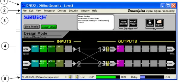
This window, shown below in Figure 1-1, is your primary work space in the software interface. You can size it propor-tionally larger, or maximize it to take up your entire screen. Closing this window exits the application.
1. Title Bar:Displays device-specific information in Live Mode. Refer to the section below for further description.
2. Main Menu:Provides access to menu commands spe-cific to the device and the signal flow diagram.
3. Control Bar:Displays controls specific to the device and the signal flow diagram. Refer to the section on the follow-ing page for more information.
4. Signal Flow Diagram: The space in which you create presets. Refer to the section on the following page for more information.
5. Status Bar:Displays controls and indicators for the signal flow diagram. Refer to the section on page 11 for more information.
Title Bar
The information on the title bar of this window changes depending upon the operating mode. In Design Mode the title bar reads, “DFR22: Offline,” and indicates the default security level. In Live Mode, it displays informa-tion specific to the unit to which you are connected, as illustrated below in Figure 1-2.
1. Device ID:The device ID is specified by setting the DIP switches on the back of the device. Refer to the Installation Guide for instructions.
2. Device Name:To name the device, in Live Mode select [Devices>Name Device] from the main menu. For more information refer to the Start-Up Guide, step 5 onpage 13.
3. Security Level:In Live Mode this indicates the current security level set for the device. For more information, refer to the Security section on page 98.
FIGURE 1-1: Main Window
1 2 3
4
5
FIGURE 1-2: Title Bar
The Main Window
Control Bar
This section of the window changes in appearance and function depending on the operating mode in which you are working, as illustrated below.
1. [Live Mode] Button:Click this button to switch to Live Mode, which enables you to preview and edit any preset currently stored in the hardware. Your computer must be connected to the DFR22 to enter this mode.
2. [Design Mode] Button: Click this button to switch to Design Mode. The preset you were working with in Live Mode remains loaded in the signal flow diagram.
3. Information Box:This displays details about the preset that is currently loaded on the screen, including name, date last saved, and description.
4. [Store Preset] Button: Click to store the current preset in the DFR22.
5. [Recall Preset] Button: Click to load a preset from the DFR22 into the signal flow diagram and work with it in Design Mode.
6. [Save As] Button:Click this button to save the current preset to your computer.
7. [Open] Button:Click to load a preset file from your com-puter into the signal flow diagram.
8. Preset Selector: Click this drop-down menu to select from the list of presets that are stored in the device.
9. LED Meters:These LED meters indicate the audio levels in the device. They can be toggled on and off by clicking on them or by selecting [View>Enable I/O Meters] from the main menu.
10. [Load] Button:Click to load the previewed preset into the signal flow diagram
11. [Cancel] Button:Click to return to the previous preset.
Signal Flow Diagram
The signal flow diagram graphically represents how audio signals pass through the gain structure of the Audio Processor and the processor blocks you put on the input and output channel strips. Each preset you create in the signal flow diagram stores the configuration of processor blocks and signal routing connections you have created. You can create presets in Live Mode or Design Mode and store them either in the device, or on your PC. In Live Mode the preset that is loaded in the signal flow diagram is the current live preset. To designate a different live preset use the drop-down preset selector in the information on box (#8 above).
1 2 3 4 5 6 7 9 10 11 Design Mode: Live Mode: Preview Mode: 8
The Main Window
Mode Indicator
This displays the current mode of the signal flow diagram, as illustrated below.
Input and Output Channel Strips
These strips are graphic representations of the input and output channels of the DFR22. They contain the gain and mix blocks that make up the gain structure of the device, as explained in the Gain Structure section on page 17. They also contain the slots in which you place the processor blocks, which you can drag and drop from the “Processor Toolbox” (seepage 11).
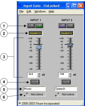
1. Input Gain Block:This is the initial stage of the Audio Processor's gain structure. Double-clicking this block opens the “Input Gain” window, which provides you with -10dBV/+4dBu scaling options, channel mute, polarity con-trol, and a +10/-infinity dB fader for each input channel. This is also where you name your input channels.
2. Input Channel Label: This displays the channel label that you specify in the “Input Gain” window.
3. Processor Slot:These slots are containers for the mod-ular processor blocks. You can populate them with proces-sors either by using the drag and drop method from the “Processor Toolbox,” selecting the [Processor>Add] option on the main menu, or by clicking the right mouse button and selecting the [Add Processor] option from the contex-tual menu.
4. Mix Points: Click on these points to route signal between input strips and output strips. Lines appear between points that are connected, representing the signal flow. Each input strip may be connected to either or both output strips.
5. Channel Numbers: These numbers correspond to each of the input and output channels.
6. Input Selectors:Click on these numbered input selec-tors at the mix point of each output strip to instantly route the signal from the corresponding input channel mix point.
7. Mix Block:This is the intermediate stage of the Audio Processor's gain structure. Double-clicking this block opens the “Matrix Mixer” window, where you can route sig-nal from either input channel strip to either or both output channel strips, and adjust levels with fader controls. This window has a separate tab for each output channel strip that displays gain, polarity, and mute controls for both input channels.
8. Output Gain Block:Double-clicking this block opens the “Output Gain” window, which provides you with -10dBV/+4dBu scaling options, channel mute, polarity con-trol, a -12dB and 18dB pad, and a +10/-infinity dB fader for each output channel. This is the final stage of the Audio Processor's gain structure. This is also where you name your output channels
9. Output Channel Label:This displays the channel label that you specify in the “Output Gain” window.
Design Mode Live Mode Preview Mode
1
2 3 4 6 7
8
9 5
The “Processor Toolbox”
Status Bar
This is the bottom section of the “Main Window.”
1. Mute Inputs:Click this control to instantly mute both input channels.
2. Mute Outputs: Click this control to instantly mute both output channels.
3. DSP Usage Meter:This indicates the percentage of the DFR22's digital signal processing resources that is used by the current configuration of processor blocks that you have
placed in the signal flow diagram. The meter displays a green bar that expands as DSP usage increases
4. Delay Memory Meter: This indicates the percentage of delay memory that is used by the delay processors you have placed in the signal flow diagram. The meter displays a blue bar that expands as usage increases.
The “Processor Toolbox”
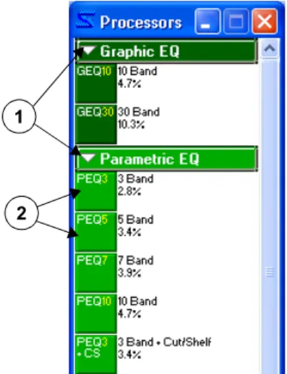
The “Processor Toolbox” appears next to the main window when you launch the application, as shown in Figure 1-6. This window displays the library of processors that you can drag and drop onto empty slots in the signal flow diagram. It can be resized vertically by dragging the top or bottom edge up or down. A scroll bar appears on the right-hand side so you can access every processor block, regardless of the height of the window.
Showing and Hiding
You can close the “Processor Toolbox” by clicking on the [X] in the right-hand corner of the title bar, or by selecting [View>Show Processor Tool-box] from the main menu. To re-open the “Processor Toolbox,” select [View>Show Processor Toolbox] again. A check mark appears next to the menu option when the “Processor Toolbox” is open.
Features
1. Drop-Down Buttons: A drop-down button appears over each proces-sor category in the “Procesproces-sor Toolbox.” Click on a drop-down button to show or hide all processor blocks within that category.
2. Processor Blocks: Processor blocks are the graphical representation of processor modules. After you place them on the signal flow diagram, you can access their settings by double-clicking on each block to open its parameter window. The percentage of digital signal processing re-sources that each processor module uses is displayed to the right of the blocks in the “Processor Toolbox.”
1 2 3 4
FIGURE 1-5: Status Bar
1
2
SECTION 2
Start-up Guide
The Start-Up Guide covers the basic steps required for complete set up of the Audio Processor. Before attempting to follow these instructions, you should familiarize yourself with the Overview section, which introduces some basic features of the software interface.
You can perform many of these steps without actually being connected to the device, by saving your presets to the com-puter and transferring them to the hardware at a later time. In order to acquaint you fully with the features of the DFR22, these instructions are written presuming the following conditions:
•
You are working while connected to the device.•
The installation includes external device control.•
Device security is required.You may find steps in the instructions that do not apply to your immediate installation. However, we suggest that you follow along through the entire Start-Up Guide, in order to acquaint yourself with the recommended workflow of setting up the device, for future reference.
Install the Software
If you have not already installed the software, follow these instructions to install the application from the CD-ROM.
To install the software from the CD-ROM:
1. Insert the CD into the CD-ROM drive of your computer.
2. The installation program will start automatically. Follow the on-screen instructions.
If installation does not begin automatically:
1. Click on the [Start] button on the Windows Taskbar and select [Run...] from the pop-up menu
2. Type “D:\setup” (where “D” is your CD-ROM drive).The installation program will start automatically. Follow the on-screen instructions.
3. Click [OK] and follow the instructions of the installation program.
If you have downloaded a copy of the software, locate the “.exe” file in the Windows Explorer and open it. Follow the instructions of the installation program.
Establish Communication with the Device
This is the procedure to use when you initially connect the computer to the device. It is your first opportunity to verify that your computer and the DFR22 are communicating properly. For more information on connecting your computer to the device and setting the device ID, see the Installation Guide.
1. Connect the Computer to the DFR22 Audio Processor
Connect your computer’s COM port to the RS-232 port on the front or rear panel of the DFR22.
2. Launch the Software Application
3. Select the COM Port
a) Select [Devices>Select COM Port] from the main menu. b) The “COM Port” dialog opens, as pictured in Figure 2-1.
c) Choose the COM port to which the RS-232 cable is connected and click [OK].
Configure External Control
4. Click the [Live Mode] button on the Control Bar
5. Name the Device
a) Select [Devices>Name Device] from the main menu.
b) The “Name Device” dialog appears, as pictured in Figure 2-2. c) Enter a device name up to fifteen characters long and click [Name].
d) The device name appears on the title bar of the main window when you are in Live Mode, and is listed in the [Devices] menu.
Configure External Control
If there are external devices connected to the control pins, you need to configure the DFR22 to recognize the external controllers. This configuration is stored at the device level and should be established before you create any presets. If you are not connected to the device, you can create a configuration and save it on the computer to be later trans-ferred to the DFR22 through the RS-232 connection. Refer to the Control Pins section on page 87 for complete step-by-step instructions.
1. Enter Design Mode
You must be in Design Mode to configure external control. If you are in Live Mode, click the [Design Mode] button on the control bar of the main window.
2. Configure Control Pins
Select [Devices>Control Pin Configuration] from the main menu, which opens the “Control Pins” window. a) Specify the number of presets you will be selecting via external control in the [# Presets] field.
b) Select the type of encoding the DFR22 must use to recognize the external hardware messages in the [Encod-ing Type] field.
c) If necessary, specify the other hardware connected for channel muting and gain control, such as potentiome-ters and switches.
3. Save the Configuration to the Device or to PC
Select the [Configuration>Store to Device] or [Configuration>Save to PC] menu option.
Note: By default you can select presets with the preset selector on the front panel of the DFR22.
Note: If you need to switch presets from the computer after you have configured the control input connec-tions, you must disable the connections in the “Control Pins” window before proceeding further. Click the arrow on the right side of the preset control block and select [Disable] from the drop-down menu.
Create a Preset Template
Create a Preset Template
This can be done in either Live Mode or Design Mode. When you are storing multiple presets in the Audio Processor, you will save considerable time by creating a preset template that contains the attributes that will be common among them. This template can then be recalled from the device or opened from a PC, revised as necessary, then stored in the device each time as a new preset.
1. Select a Preset Template
When you start the DFR22 application there is a blank preset in the signal flow diagram. If you would like to use one of the other default presets as a template, select [File>New] from the main menu and then select [Dual Mono], [Stereo], or [Dual Mono Split]. You can also go to Live Mode and select one of the pre-loaded presets to edit. For more information, refer to the Default Presets section on page 27.
2. Name Input and Output Channels
Double-click on the input and output gain blocks to open the processor parameter windows, and edit the channel labels that appear underneath the gain controls. For more information, refer to the Labeling Inputs and Outputs section on page 18.
3. Populate the Signal Flow Diagram
Drag and drop signal processor blocks from the “Processor Toolbox” onto the signal flow diagram. If you are using a crossover, it should be the first type of processor that you place in the configuration, followed by limiters, in order to prevent loudspeaker damage. For more information, refer to the Adding Modular Processors section on page 21.
4. Create Link Groups
Ctrl+ Click to select multiple processors of the same type that you would like to control as a group, for stereo pairs, loudspeaker clusters, zones, etc. You can also link gain blocks in order to control overall system level. Select [Processor>Link] from the main menu. For more information, refer to the Linking section on page 24.
5. Engage Pads on Outputs
You may need to engage the 12dBor 18dB pad to better align the output clipping level of the DFR22 with the input clipping level of the equipment to which it is connected. Double-click on an output gain block to open the “Output Gain” window and click to activate each pad as needed.
6. Route Signal From Inputs to Outputs
Click and drag from input strip connection points to output strip connection points to route the signal through the matrix mixer. For more information, refer to the Signal Routing section on page 19.
7. Adjust Processor Settings
Double-click on each processor block to open its parameter window. If you are working off-line in Design Mode, you can set preliminary levels and tweak them later when you are connected to the device. For more information on working with processors, refer to the Processor Features section on page 33, as well as the reference section for each processor.
8. Map the Preset to Control Connections
This step is applicable only when you are controlling gain and/or channel muting via the control pins. Select [Devices>Control Pin Configuration] from the main menu to open the “Control Pins” window. Select [Configura-tion>Recall From Device] to populate the window with the current pin configuration. The input and output channels
Manage Your Presets
are listed in a column under each connection block. Click the checkbox next to each input or output channel you wish to map to the control connections. For more information, refer to the “Processor Mapping” section on page 95.
9. Lock Processors for Read-Only Access
This step is applicable only when you are customizing security for end users accessing the DFR22 from the soft-ware. This type of security is stored with each processor, at the preset level. Select the processors that the user should not be able to modify, and select [Security>Level 2>Lock Selected] from the main menu. For a complete explanation and further instructions, refer to the Individual Processor Security section on page 101.
10. Name the Preset
Click once with the left mouse button anywhere in the information box in the center of the control bar to open the “Preset Information” dialog, as pictured on the right in Figure 2-3. Enter a name for the preset, up to 15 characters long, and a description, then click [OK]. For more information, refer to the Naming a Preset section on page 20.
Manage Your Presets
1. Store the Finished Preset in the Device
If you are working in Live Mode, the preset is already stored in the
device. If you are working in Design Mode, click the [Store Preset] button on the control bar of the main window. For more information, refer to the Device Presets section on page 29. To duplicate this preset you need to be in Design Mode. Simply continue to click the [Store Preset] button, creating duplicates until you have stored as many presets in the device as you require.
2. Delete Unused Presets from the Device
The device comes pre-loaded with three presets. If you are not going to use them, you should delete them from the device so end users cannot access them. (If you need them again later, you can recall them from the [File>New] menu.) See the Delete a Preset section on page 30 for instructions.
3. Enable External Control
Once you are finished creating and editing presets, if you previously disabled control connections in order to con-trol the Audio Processor via the computer, open the Concon-trol Pins window and re-enable them. See the IMPOR-TANT NOTE ON PRESET SWITCHING: section on page 88 for more information.
Establish Security
Establish Security
This is the final step in setting up the device. Before continuing, you should thoroughly read the Security section on page 98. These instructions are intended only as an overview of the process.
1. Go Live with the DFR22
You must be in Live Mode to set device security. If you are in Design Mode, click the [Live Mode] button on the control bar of the main window.
2. Set the Front Panel Lockout
Select [Security>Front Panel Lockout] from the main menu, which opens the “Front Panel Lockout” dialog. Select the checkbox next to each front panel feature for which you wish to lockout end user access. Use this software fea-ture to selectively lock out front panel controls. To lock out all front panel controls you can also set the fifth DIP switch on the back of the device to the down position.
3. Set a Password
Select [Security>Set Password] from the main menu, which opens the “Create Password” dialog. Type in a pass-word, press Tab, and then type it again to confirm. Click [OK].
4. Set the User Access Level
Select [Security>Set Level] from the main menu, which opens the “Set Security” dialog. Select the appropriate user access level. Click [OK].
SECTION 3
Creating a Preset
A preset is a unique combination of signal routing connections, the variety and placement of modular processors, and the processors’ settings. You create the configuration in the signal flow diagram of the main window, and either save it as a preset in the device, or save it to the computer as a file that you can send to the device later.
Signal Flow Configuration
In order to pass audio through the device, you must route signal from the inputs to the outputs by connecting mix points. This section explains the basics of signal flow design in the DFR22 user interface.
Gain Structure
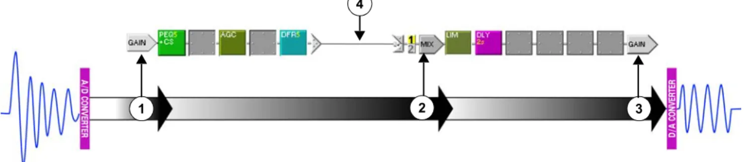
The DFR22 Audio Processor provides gain control at three stages of the signal flow: input gain, matrix mixer, and output gain. It is essential to obtain an understanding of this gain structure before passing audio through the unit, in order to avoid damaging equipment that is in line after the Audio Processor with excessive gain levels. The follow-ing illustration provides an overview of the DFR22 gain structure.
1) Input Gain
Double-clicking on either input gain block will open the “Input Gain” processor window, which displays controls for both channels. It provides input sensitivity, gain and polarity control for each channel, and allows you to specify custom names for your input channel strips.
This is a signal's point of entry to the signal flow diagram. After the input gain processor, the signal passes sequentially through the processor slots on its input channel strip. At the end of the channel strip, the signal arrives at a mix point, where it can be routed to either or both outputs via the matrix mixer.
2) Matrix Mixer
Once a signal has been routed to the mix point of an output channel strip, it enters the matrix mixer stage of the gain structure. Double-click on any mix block to open the “Matrix Mixer” processor window, which displays a pane for each output channel strip. When the crossover or splitter is placed over both output channels, the mixer panes for those channels will combine into one. Use this window to adjust the polarity and relative levels of the input(s) routed to the selected output channel.
After the matrix mixer, the signal passes sequentially through the processor slots on the designated output strip. At the end of the channel strip, the signal arrives at the output gain block.
Note: Signal levels exceeding the input threshold of the Audio Processor must be adjusted externally to prevent clipping at the A/D converters.
1 2 3
4
Signal Flow Configuration
3) Output Gain
This is the final stage of gain control in the Audio Processor. Double-click on any output gain block to open the “Output Gain” processor window. It provides output sensitivity, gain, polarity control, and an optional 12 dB and 18 dB pad for each channel. This window also allows you to specify custom names for your output channel strips. After the output gain processor the signal passes through the D/A converter, then through the analog pads (if engaged), to the audio output.
4) Signal Routing Connection
This can be created in the signal flow diagram by clicking and dragging between mix points, by clicking on an input selector directly to the left of the MIX block, or by opening the “Matrix Mixer” window and selecting the input. For more information see the Signal Routing section on page 19.
Muting Channels
There are several ways to mute the input and output channels of the Audio Processor. Muted channels are flagged in the signal flow diagram, as illustrated in the following table.
Muting all Inputs or Outputs
•
Click either the Mute All Inputs or Mute All Outputs control located on the status bar of the main window.•
Select either the [Processor>Mute All Inputs] or the [Processor>Mute All Outputs] menu option.•
Power off the device to automatically mute all outputs.Muting Individual Channels
1. Open the “Input Gain,” “Matrix Mixer,” “Crossover,” or “Output Gain” window by double-clicking the appro-priate processor block.
2. Click the mute button for the appropriate channel.
3. The block will be flagged with a red “M” to indicate that it is muted.
Labeling Inputs and Outputs
Inputs and outputs are untitled when you create a new preset, but they are easily changed using the “Input Gain” and/or “Output Gain” windows. Channel labels are saved along with the preset, so you can customize input and output labels for every preset.
To change a channel label:
1. Double-click on the channel's gain block.
2. In the processor window, locate the channel's label box.
Gain Block Matrix MixerInputs to Crossover Output Channels
Signal Flow Configuration
4. Type in a new label of no more than fifteen characters.
5. Apply the changes by clicking on another control or closing the window.
Signal Routing
The DFR22 allows you to route signal from either of the two inputs to either or both of the outputs. In order for sig-nal to pass from the input channel strips to the output channel strips, it must be routed through the matrix mixer. You can connect inputs to outputs using any of the methods described below.
Making Connections in the Signal Flow Diagram
For simple system configurations, the easiest way to connect inputs to outputs is to use the mouse in the sig-nal flow diagram.
Click on Mix Points:
1. Click on an input mix point.
2. The cursor will change to indicate it’s waiting for you to specify an output connection: 3. Click on an output mix point.
Click and Drag Between Mix Points:
1. Click and drag from an input mix point to an output mix point.
2. A connection line will appear along the signal path. It turns green when the connection is valid. 3. Release the mouse button to make the connection.
Click on the Input Selectors:
1. Click on an output channel's numbered input selector for the corresponding input channel.
2. A connection line will appear in the signal flow diagram between the mix points, and the numbered input selector will be highlighted.
Making Connections in the “Matrix Mixer” Window
For more complex configurations with many crossing connection lines, the “Matrix Mixer” window can provide an easier method of connecting inputs to outputs.
To make connections in the “Matrix Mixer” window:
1. Double-click on the mix block for the output you wish to connect. 2. The “Matrix Mixer” window opens.
3. In the left side of the window, click the input button for each input channel you wish to connect to the selected output. The input button lights green when a connection is made.
4. A connection line will appear in the signal flow diagram between the mix points, and the numbered input selector will be highlighted for each active connection.
Deleting Connections
•
Click on a connection line and press the Delete key.•
Click on the input selector corresponding to the connection. This toggles the connection off.Tip! You can use the Esc key to cancel a connection if you change your mind after you have clicked on an input mix point, before you click on an output mix point.
Processor Configuration
Naming a Preset
Since you can store up to 16 different presets in the DFR22, it can be helpful to differentiate them with a name and a brief description. The information box in the center of the control bar of the main window displays these details, as pictured below in Figure 3-2.
The name you enter here becomes both the name of the preset when you store the configuration to the device, and the name of the file when you save it to PC. The description will also be displayed in all the dialog boxes that list presets. You can revise these details at any time in either Live Mode or Design Mode.
To name a preset:
1. Click once with the left mouse button anywhere in the information box.
2. The “Preset Information” dialog opens.
3. Enter a name with a maximum of 15 characters and a description with a maximum of 80 characters.
4. Click [OK]
5. The information box updates to reflect your changes.
Processor Configuration
There are two levels of working with processors: at the configuration level in the signal flow diagram, and within each processor's individual parameter window, which is accessed by double-clicking on the processor block. This section covers working with processors in the signal flow diagram, and explains the differences between the two main catego-ries of processors.
Processor Types
You will be working with two main types of processors in the signal flow diagram: fixed and modular. The primary distinction between them is that fixed processors are part of the gain structure of the DFR22, and are therefore part of every signal flow configuration. Modular processors are the processor blocks that are listed in the “Processor Toolbox,” and that you can select and position to suit your particular system requirements.
Fixed Processors
The gain and mix blocks are called fixed processors because their locations on the channel strips are perma-nent. They cannot be deleted, moved, copied, or pasted. However they can be linked, and their settings can be saved and recalled.
Modular Processors
The modular processor blocks are called modular because they can be placed on any empty slot (excepting the crossover, splitter, subwoofer and the ducker), and freely moved, copied, pasted and deleted. Each pro-cessor block on the signal flow diagram functions independently. When you open the parameter window of a modular processor, you are changing settings for that block only, except under the following conditions.
•
It is half of a stereo pair.FIGURE 3-2: The Information Box
Processor Configuration
Adding Modular Processors
Each channel strip has a row of empty slots that can contain any of the modular processor blocks. Except for the crossover, subwoofer, splitter, and ducker, there are no restrictions on where processors can be placed on the sig-nal flow diagram, or how many times you can use a given processor on the same channel strip. Empty slots between processors do not affect the signal flow, so blocks do not have to be adjacent on the channel strips. When processor blocks are first added to the signal flow diagram, they contain factory default settings. You can individually change each processor's settings by opening its parameter window. The blocks will retain their settings even when copied or moved to a different slot.
Processor blocks can be added to the signal flow diagram either by using the “Processor Toolbox,” or by menu command. Each method is described below.
Using the “Processor Toolbox”
You can use the mouse to grab a processor block from the “Processor Toolbox.” The mouse cursor will change to alert you that your next mouse action will place the block in the signal flow diagram. The cursor's appearance depends on its location, as illustrated in the following table.
To add a processor block from the “Processor Toolbox:”
1. Point and click on a processor block in the “Processor Toolbox.” 2. Hold the mouse button down and drag the block to the signal diagram. 3. Release the mouse button to place the block at the current cursor location. OR
-1. Point and click on a processor block in the “Processor Toolbox.” 2. Click on the appropriate empty slot in the signal flow diagram.
Using a Menu Command
You can add processors to the signal flow diagram without opening the “Processor Toolbox,” by using either the main menu or the right-click contextual menu, as described below.
To add a processor block using the menu:
1. Click to select an empty slot.
2. Use the right-click contextual menu to select a processor. OR
-Use the [Processor>Add] option on the main menu bar.
Another advantage to using a menu command to place your processor blocks is that you can place the same type of processor in multiple slots with a single menu command.
Location where processor can be placed.
Inappropriate location for that processor.
Tip! If you change your mind after you have clicked on a processor block in the “Processor Toolbox” win-dow, you can use the Esc key to cancel this operation before you place the processor in the signal flow diagram.
Processor Configuration
To add multiple processor blocks at once:
1. Ctrl + Click to select multiple empty slots.
2. Use the right-click contextual menu to select a processor. OR
-Use the [Processor>Add] option on the main menu bar. 3. The processor will populate all the slots that you selected.
Stereo Processors
Stereo processors are placed in the signal flow diagram in much the same way as the other modular processor blocks. However, each of the stereo channels appears as a separate block. Double-clicking on either block will open the parameter window for both channels.
Each of the following processors operate as a stereo pair:
To add a stereo processor block from the “Processor Toolbox:”
1. Click on a stereo processor block in the “Processor Toolbox.”
When you select a stereo processor from the “Processor Toolbox,” the cursor will appear somewhat differ-ently than it does for other processors, as pictured in the following table.
2. Add the first channel of the stereo pair using one of the following methods.
a) Click and hold the left mouse button to drag a processor block from the “Processor Toolbox” to the sig-nal flow diagram.
b) Release the mouse button to place the first processor channel at the current cursor location. OR
-a) Click once on a processor block in the “Processor Toolbox.”
b) Click again on the appropriate empty slot in the signal flow diagram.
3. The cursor changes to indicate you must place the second channel of the processor. 4. Click on the appropriate slot to add the second stereo channel.
To add a stereo processor using the menu:
1. Ctrl + Click to select empty slots on two different channels.
2. Use the right-click contextual menu to place both channels of the stereo pair. OR
-Block Name Description ST DFR 5 Stereo 5-Band DFR ST DFR 10 Stereo 10-Band DFR ST DFR 16 Stereo 16-Band DFR ST COMP Stereo Compressor
Sft ST COMP Stereo Soft-Knee Compressor ST LIM Stereo Limiter
Sft ST LIM Stereo Soft-Knee Limiter
Location where the first channel of the stereo processor can be placed.
Location where the second channel of the stereo processor can be placed.
Processor Configuration
Replacing Processors
Only one processor block at a time can occupy a given slot. To replace an existing processor with another, first delete it from the slot then add the new processor using any of the methods described above.
The Crossover, Splitter, and Subwoofer
Since they are output processors, the crossover, splitter, and subwoofer can only be placed on output chan-nel strips. They can be added to output strips like any other processor block, but you must take into account the following:
•
The crossover extends downward to span both outputs, so you must place it on channel one.•
The mix point will disappear from the second channel after the crossover is placed above it.•
Processor slots will disappear from the second channel, to the left of the crossover block.•
The splitter will affect the signal diagram as listed above for the crossover.The Ducker
The ducker should be placed only on the input channel strip that carries the paging signal. You are restricted from placing a ducker on an output strip.
Copy and Paste
The traditional copy, cut and paste commands function only on the modular processor blocks. This is a convenient way to duplicate processor blocks along with their settings across multiple channels.
To copy and paste a processor block:
1. Point and click to select a processor block.
2. Select the copy command using one of the following methods:
•
Use the right-click contextual menu.•
Select [Edit>Copy] from the main menu.•
Press Ctrl + C on the keyboard. 3. Point and click to select an empty slot.4. Select the paste command using either the main menu, the right-click menu, or press Ctrl +V.
Deleting Processors from Slots
Modular processor blocks can easily be removed from a configuration without affecting any other aspect of the signal flow.
To delete a processor block:
1. Point and click to select a processor block.
2. Select the delete command using one of the following methods:
•
Note: If your configuration calls for a crossover or splitter, it should be added to the signal flow diagram before you connect mix points or add other processors to the output channel strips.
Processor Configuration
Linking
You can link multiple processor blocks of the same type in order to control them as one. Changes made in the pro-cessor parameter window of any block in a link group will simultaneously change the settings of every other block in that group. There are a few activities, however, that will still function independently on linked blocks:
•
Delete, Copy, Cut and Paste,•
Moving the block to a different slot or channel strip,•
Naming the processor parameter window.Fixed processors at the same stage of the gain structure can also be grouped, which will synchronize the level controls for all of the grouped channels. For example, you can group two input channel gain blocks in order to con-trol them as a stereo pair. You can also link both output gain blocks, in order to adjust the output channel levels overall from a single control.
Creating a Link Group
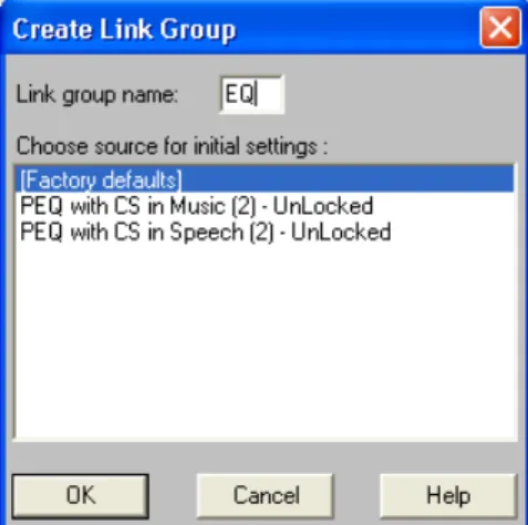
When you first create a link group, all of the processors in that group will synchronize to the same settings. If you have already specified settings for one of the processors prior to creating the link group, you can desig-nate it as the source when you first create the group, causing the other processor blocks to inherit those set-tings. Alternately, if you would like to discard any previous processor settings, you can select the factory default settings as the initial source. After the link group is created, changes to settings of any of the linked blocks will affect all blocks in that group.
To create a link group:
1. Ctrl + Click to select multiple processor blocks.
2. Select [Processor>Link>New Link Group from the main menu, or [Link>New Link Group] from the right-click contextual menu. 3. The “Create Link Group” dialog appears, as pictured to the right
in Figure 3-4.
4. Enter a two-character name for the link group. 5. Choose a source for the initial link group settings. 6. Click [OK] to accept the settings.
The two-character link group name appears both on the processor block in the signal flow diagram, and in the link indicator at the lower right-hand corner of the processor parameter window, as illustrated in the following table.
Adding to a Link Group
Processor blocks can be added to an existing link group, if they are the exact same type of processor and they are currently unlinked. Any processor added to a link group will inherit the group's current settings.
Note: Only processors of precisely the same type can be linked.
Processor Parameter Window Signal Flow Diagram
Note: Processors can belong to only one link group at a time.
Processor Configuration
To add blocks to an existing link group:
1. Click to select a processor block, or Ctrl + Click to select multiple blocks.
2. Select [Processor>Link>Add To] from the main menu, or [Link>Add To] from the right-click contextual menu.
3. The “Add to Link Group” dialog appears, as shown in Figure 3-5. It lists only the link groups that contain processors identical to the selected block.
4. Select a link group. 5. Click [OK]
Unlinking Processor Blocks
Processor blocks can be removed from a link group without affecting other linked blocks. You can also dis-solve a link group by unlinking all the blocks in the group.
To remove blocks from an existing link group:
1. Click to select a processor block, or Ctrl + Click to select multiple blocks.
2. Select [Processor>Link>Unlink] from the main menu, or [Link>Unlink Selected] from the right-click contex-tual menu.
Bypassing
From the main window, you can bypass any modular processor block. This lets you evaluate the signal path while temporarily excluding a processor. Bypassed blocks in the signal flow diagram display a yellow flag, as shown in Figure 3-6.
To toggle bypass on or off:
1. Click to select a processor block, or Ctrl + Click to select multiple blocks. 2. Activate bypass with any of the following methods:
•
Press Ctrl+B on the keyboard.•
Select [Processor>Bypass Selected] from the main menu.•
Select [Bypass Selected] from the right-click contextual menu.Managing DSP Resources
Although the DFR22 has sufficient processing power for many applications, it is possible to populate the signal flow diagram with more processor blocks than the device's DSP (digital signal processing) resources can handle. This section explains in general terms how the Audio Processor manages the signal processing requirements of a configuration, and gives you some hints on how to get the most out of the DSP resources.
Resource Allocation
By placing a processor block on a channel strip, you are allocating the DSP resources necessary for it to run at its maximum capacity. This is why so many varieties of the same type of processor blocks are provided; so that you can select only the amount of processing you actually need for a given module. When you are designing a simple configuration, it is not critical to pay attention to how much DSP is being utilized. However, the more
Note: A link group must contain at least two processor blocks. Removing all but one block from a link group will delete the group.
FIGURE 3-5: “Add to Link Group” Dialog
FIGURE 3-6: Bypassed Processor Block
Processor Configuration
For example: when you place a ten-band parametric EQ on a channel strip, you will instantly allocate the pro-cessing power required by all ten filters, even if you are only using four of them. The PEQ5 would be the best choice, in this instance.
Delay Memory
The DFR22 has a memory buffer that will hold up to 10 seconds of delay time, which you can divide among any combination of delay processors. Like DSP resources, delay memory is allocated to each processor block according to the maximum delay time indicated in the block name.
For example, if you need 45 ms of delay, don't use the 2-second delay when the 150ms delay will do just as well. Even though both processors may be set to the same values, the DLY 2s block still occupies a full two seconds of delay memory.
DSP Usage Meters
These meters, located on the status bar at the bottom of the main window, indicate the amount of DSP resources and delay memory utilized by the current configuration. Knowing the amount of DSP resources and delay memory you have left enables you to manage your processor choices efficiently. When you add or remove a processor block from the signal flow diagram the DSP meter instantly compiles the results, and indi-cates the system resources that are being utilized by the current processor configuration.
DSP Optimization Hints
If the message box shown in Figure 3-7 appears when you attempt to add a processor, optimize your configuration to free up DSP resources, then add the processor. The following hints will help you optimize DSP resources.
•
Replace DFRs with parametric EQs after you are finished ringing out the system.For example: in a configuration where multiple DFRs are needed on multiple inputs for better gain before feedback performance, you could initially use a DFR on each input for ringing out the sys-tem. After the filters are deployed, copy the DFR filters and paste them in a PEQ, then delete the DFR. You can repeat this for the other input, then leave only the DFRs that are necessary for
auto-matic feedback detection after the system has been configured. For more information on copying and pasting filters between processors, see the Copy and Paste section on page 71.
•
Consolidate multiple EQs on the same signal path into a single module, if possible.Example: two PEQ3s consume more DSP than a PEQ7. Note that all PEQ's are available with cut and shelf filters in order to conserve DSP. If you don't require the additional slope choices of the CUT/SHELF processor, it is not necessary to include cut and shelf filters in a separate module on the same signal path.
•
Consolidate multiple delays on the same signal path into a single module, if possible. Using two DLY5ms blocks to achieve 7 ms of delay uses twice as much DSP than a single DLY150ms block, even though it conserves Delay memory.•
Remove processors from any unused channels.•
Use the splitter to consolidate identical signal processing on both output channels.•
Use a PEQ10 instead of a GEQ30. In most cases, you will not use all thirty filters on the GEQ30, and the PEQ10 uses less than half as much DSP.Note: Do not confuse delay memory with DSP resources. Each delay utilizes the same amount of DSP, regardless of its maximum delay time.
Default Presets
Default Presets
To help you get started with basic configurations, the DFR22 comes loaded with three default presets. These presets are also listed in the [File>New] sub-menu, so you can use any of them as a template to create a new preset.
Preset One – [Dual Mono]
In this configuration input one is routed to output one and input two is routed to output two. Each input strip is pop-ulated with the following processors:
•
DFR16 - assigned to the front panel controls•
PEQ10+CS•
GEQ30•
LIMIn addition, each output strip has a 2-Second Delay, set to 0ms by default.
Preset two – [Stereo]
In this configuration input one is routed to output one and input two is routed to output two. The input channels are linked, as are the output channels, so you can control gain on both channels simultaneously at both the input and output stages of the gain structure.
The input strips are populated with the following processors:
•
Stereo DFR16 - assigned to the front panel controls•
Linked PEQ10+CS’s•
Linked GEQ30’s•
Stereo LimiterIn addition, the output strips are populated with linked 2-Second Delays, set to 0ms by default
Preset Three – [Dual Mono Split]
In this configuration input one and input two are each routed to both output one and output two. The input strip is populated with the following processors:
•
DFR16 - assigned to the front panel controls•
PEQ10+CS•
GEQ30•
LIMIn addition, each output strip has a 2-Second Delay, set to 0ms by default.
Note: You should either lock out the front panel preset selector or delete the default presets in the device that you are not using so end users do not access them by mistake.
SECTION 4
Preset and Device Management
In Design Mode after you create a preset, you can save it either to the computer, or to the device, depending on whether or not you are connected to the DFR22. At any time, one and only one preset is active in the DFR22. This preset is referred to as the live preset. When you are in Live Mode, the preset you are viewing or modifying is the current live preset. You can save it to the PC at any time by clicking the [Save As] button on the control bar of the main window.
Preset Files
You can design an entire library of presets with the DFR22 software without being connected to the device. Presets saved to PC can be later recalled, revised, and then sent to the device. They are saved with a “.d22” file extension.
Saving a New Preset to Your Computer
If you are not connected to the device, you will be saving each new preset to the computer.
To save a new preset to the computer:
1. In the main window, select [File>Save As] from the main menu or click the [Save As] button on the control bar.
2. The “Save As” dialog will appear.
3. Navigate to the drive and directory location for the new file. 4. Type in a file name and, optionally, a description.
5. Click [Save].
Revising Preset Files
When you make changes to an existing preset, you can either save it to PC with a different file name, or overwrite the previous version.
To revise a preset stored on the computer:
1. In the main window, select [File>Open File] from the main menu or click the [Open] button on the control bar. 2. The “Open” dialog will appear.
3. Navigate to the drive and directory location of the preset file you wish to open. 4. Click on the file to select it, then click the [Open] button.
5. Make the necessary changes.
6. Select [File>Save As] from the main menu or click the [Save As] button on the control bar. 7. The “Save As” dialog will appear.
8. Click on the original file name to select it, then click [Save].
9. A dialog box will appear that prompts you to verify that you want to overwrite the previous preset file. 10. Click [Yes] to overwrite the file.
Note: The first fifteen characters of the file name and the first 80 characters of the description appear in the information box on the control bar.
Device Presets
Device Presets
The DFR22 can store 16 presets in its device memory. Once presets are stored in the device, they can be renamed, deleted, or backed up as a set.
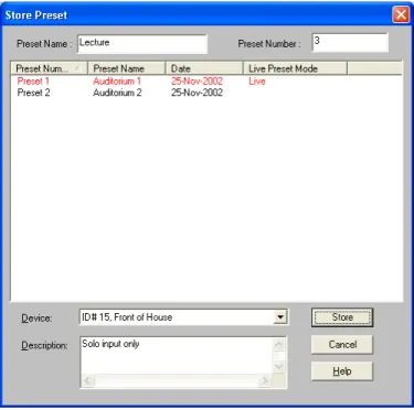
Store a Preset in the Device
When you are connected to the device, in Design Mode you can store new presets in the device, or open existing preset files and store them to the device.
To store a preset in the device:
1. In the main window, select [File>Store As Preset] from the main menu, or click the [Store Preset] button on the control bar.
2. If the “Select Devices” dialog appears, as pictured in Figure 4-1, select a device from the list and click [Connect]. 3. The “Store Preset” dialog will appear, as pictured below in
Figure 4-2.
4. Type in a preset name of no more than fifteen characters. 5. Type in a preset number, or accept the default.
6. Type in a description (optional), which will help identify the contents of the preset for further operations.
7. Click [Store].
FIGURE 4-1: “Select Devices” Dialog
Device Presets
Rename a Preset
After you have stored a preset in the device, you can change its name and description in Live Mode. You can also change the name of a preset stored to PC in Design Mode.
To rename a preset stored to the device:
1. Click on the [Live Mode] button on the control bar.
2. Select the preset you wish to rename from the pull-down menu in the informa-tion box on the control bar.
3. The main window will enter preview mode for the selected preset. 4. Click the [Load] button on the control bar to make it the live preset. 5. Click once anywhere in the information box.
6. The “Preset Information” dialog will appear, as pictured to the right in Figure 4-3.
7. Type in the new name and/or description. 8. Click [OK].
To rename a preset stored to PC:
1. Go to Design Mode. 2. Open the preset file.
3. Click once anywhere in the information box.
4. The “Preset Information” dialog will appear, as above. 5. Type in the new name and/or description.
6. Click [OK].
7. Resave the preset to PC.
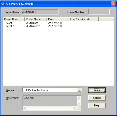
Delete a Preset
The current live preset will not be available for deletion. If you need to delete this preset, you must first select a different live preset.
To delete a preset:
1. Click on the [Design Mode] button on the control bar.
2. Select [File>Delete Preset].
3. If the “Select Devices” dialog appears, select from the list of available devices and click [Connect]. 4. The “Select Preset to delete” dialog will appear, as
pictured in Figure 4-4.
5. Select the preset you wish to delete, or
Shift + Click to select multiple presets. 6. Click [Delete].
FIGURE 4-3: “Preset Information” Dialog