Visio Tutorial
1BB50 Data and Object Modeling (DOM) How to make a UML Class Diagram
2004/2005
Table of Contents
1. Starting up Visio ... 1
2. Add a class to your diagram ... 2
3. Set the display options for class rectangles ... 4
4. Define attributes for a class ... 5
5. How to choose or define data types for attributes ... 6
6. How to add objects ... 9
7. Add associations ... 11
8. Add associations ... 12
9. Generalization ... 14
10. Association Classes ... 16
11. Defining uniqueness constraints and standard identifiers ... 18
12. Add associations ... 21
Starting up Visio
1. Startup Microsoft Visio (2000, 2002 or 2003)
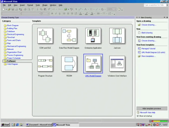
2. Now you have to choose your Drawing type. First select the 'Software' folder and then click on the 'UML mod-el Diagram' icon and/or choose "UML Static Structure Diagram" (see Figure 1).
3. For this course we use 'UML Static Structure' (this is another term for class diagram). When you choose this, you will see the various shapes for building a UML class diagram on the right of the main window. (When you place your cursor on one of the shapes you will see a short description of it.)
4. Before making a UML diagram you'll may want to change the paper orientation in the main window to land-scape by going to File > Page Setup.
Add a class to your diagram
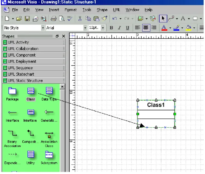
5. Click on the 'Class'-shape (this represents an object class) and drag it to the main window as shown in Figure 2.
Figure 2. Drag and drop a class rectangle.
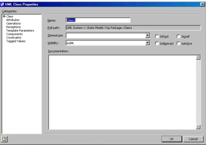
6. To change the name of the class you will have to double click on the class. A window 'Class properties' will ap-pear (see Figure 3). You can change its name in the name field. Change the name from 'Class1' into 'Patient'.
Figure 3. Give a class a name
Set the display options for class rectangles
7. You'll see that a class rectangle generally has three compartments. In most cases we need only one or two com-partments (one for the name of the class and possibly one for its attributes). For changing the display settings of a class you first have to put your cursor on the class. Then click on the right mouse button and select 'Shape Display Options'. The window like in Figure 4 will appear. Now you can suppress the third compartment by se-lecting 'Operations' (see arrow 1). Under "General Options", unmark all settings except "Name". Under "Attrib-ute", generally unmark all settings (later you may mark "Attribute types" or "Attribute multiplicity" if you want to see this in your diagram). Make sure that your settings will apply to each class you draw by marking the field to which arrow 2 points.
Figure 4. Changing UML Shape Display options
Define attributes for a class
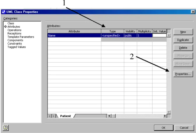
8. You can add attributes to a class by clicking on the category 'Attributes' on the right side of the 'Class proper-ties' window. You can now add the following attributes of the class 'Patient': Name, Gender, Birthdate, and Ad-dress.
Figure 5. Adding attributes to a class
How to choose or define data types for attributes
9. After adding an attribute to a class, you can specify the data type of the respective attribute in the column "Type" (see arrow 1 in Figure 5). When you click on this compartment, you can choose various data types from a scroll-down list. For this course we use the Visual Basic attributes in most occasions. These are indicated with a VB in front of the type, for example VB::Char, VB::Decimal, VB::Integer. (You don't have to use the rest of the columns (Visibility, Multiplicity, Int. Value)). Now include the following data types for the attrib-utes of the Patient-class.
• Name: Char • Gender: Char • Birthdate: Date • Address: Char
When you return to the main window you will see the data types appearing in front their respective attribute. 10. However it is also possible to define your own data types. You can do this by defining a new data type -
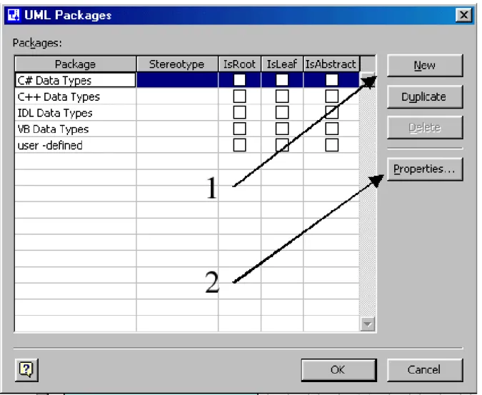
pack-age. On the main window, click on the UML > package option. The window given in Figure 6. will appear. Here, choose the 'New' option as indicated with arrow 1.
Figure 6. Click on the 'New' button
11. Now a new package, named 'Package1', will appear on the list. Change this name by going to its properties (arrow 2 on Figure 6). A window like in Figure 7. will appear; here you can change its name. Now change this name into 'User-defined', and click on OK.
Figure 7. Changing the name of anew data type package
12. When returning to the main window you can see on the bottom-left window, named the 'Model Explorer', a new 'User-defined' folder (see Figure 8.). Now, you can add new data types by clicking the right button while having the cursor on the 'User-defined' folder. Then choose New > Data type.
Figure 8. Adding a new data type
13. In the window 'UML data type properties' you can define a new data type by entering its name in the "Name" field. For example, enter the SQL data type "Char(30)" in the name field. After that, go back to the data type scroll-down list of an attribute (see point 9). You can see that the data type Char(30) is added to the list. 14. Now try to make/define the following data types in the same way explained above: Char(1), Char(255). Then
make the following class in Figure 9. As an exercise for you try to make 'Consultation' as indicated in Figure 10.
Figure 9. Attributes with user defined data types
How to add objects
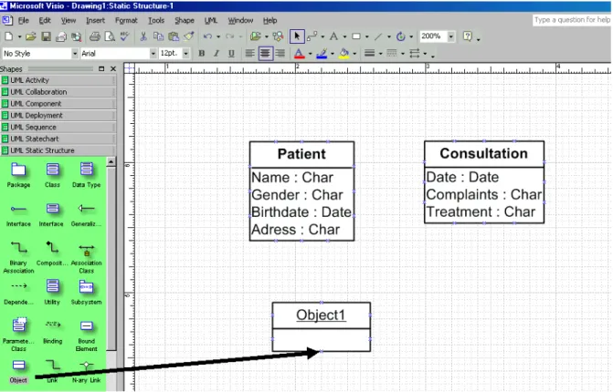
15. You can draw object in the same as class rectangles by dragging the 'object'-shape to the main window (see Figure 10).
Figure 10. Drag and drop an object rectangle
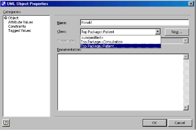
16. Like a class you will have to double click on the object for changing its properties. The window given below will appear. In the name field you can change the name of the object. Under the name field you can specify the class to which the object belongs. When you do this the object inherits all the attributes of its class.
Figure 11. Add an object to a class
Add associations
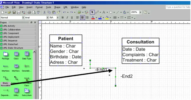
17. Now that we have two classes we can draw an association between them. You can do this by dragging the 'Bin-ary Association' shape to the main window (see Figure 12). A line will appear then. You have to drag both ends of the line to the two classes. When you drag an end of a line to a class rectangle it will turn red when.
Figure 12. Drag and drop an association
Add associations
18. You see in Figure 12 that the name of the association doesn't appear on the screen. Instead of tat you see names 'end1' and 'end1' appearing on both ends of the association. You can use these end names to specify a role of a certain class. However, we can change these display settings by moving the cursor above the association and clicking the right button. Then select 'Shape Display Options' (like in point 7). Mark 'Name' in the General Op-tions. Also, unmark the 'first end name' and the 'second end name' in the end options (make sure that this will apply to subsequently dropped UML shapes by marking this). Returning to the main window you will see the name 'Association1' written above the association.
Figure 13. The name of an association
19. Double click on the association to specify it. Then a window like Figure 14 will appear. In this window you can give the association a name and/or enter role names in the column "End Name" (when this option is marked in the Shape display options, see point 18). Now write 'has' in the name field and add the multiplicity symbols "1" at the association end 1 and "0..*" at association end 2.
Figure 14. Adding a name and multiplicity constraints
20. Returning to the main window your class diagram will look like Figure 15.
Figure 15. Class diagram
Generalization
21. Generalizations can be expressed with the help of generalization arrows. Drag this arrow to the main window, and then connect both ends to connection points at the class rectangles concerned (see Figure. 16). (Make sure that you connect the arrow end to the superclass 'Employee' and the other end to the subclass 'Nurse.')
Figure 16. Drag and drop a generalization arrow
22. You can simply add multiple subclasses to a superclass. In Figure 17 you can see how the subclass 'Doctor' is added to the superclass 'Employee'. (Make sure that the arrow ends overlap each other.)
Association Classes
23. Like a class, an association can also have properties. Whenever one or more properties of an association are to be included in a model, the association has to be turned into an association class. To make one you have to se-lect and drag the 'Association Class'-shape to the main window (see Figure 18). Make sure you connect both ends to the participating class rectangles.
Figure 18. Drag and drop an association class.
24. Double click on the association class and its property window (Figure 19.) will appear. Now you can give the association class a name and add multiplicities. You can add attributes by going to the attributes window. 25. You can suppress the appearance of the 'end names' in the Shape display options. Like in point 7, you have to
hold the cursor above the association class and click on the right mouse button. Then unmark the 'first end name' and the 'second end name' in the end options.
Figure 19. Naming the association class
Defining uniqueness constraints and standard identifiers
26. For including a uniqueness {unique}or standard identifier {stdid} constraint to an attribute you have to go the properties window of that attribute (see arrow 2 of Figure 5). Now go to the properties of the attribute 'Name' of the patient class. Then the window given below will appear. Now you have to add {unique}or {stdid}in the 'Suffix' field with a leading blank space (see arrow in Figure 20.). When returning to the main window you will see the text you entered appearing behind the attribute (See Figure 21.).
Figure 20. Adding an uniqueness constraint to an attribute
Figure 21. Uniqueness constraint added
27. For the situation that uniqueness constraint is defined by a combination of two attributes (like Name and Birth-date) we use another method. Now we choose a line above and connect this line to the attributes (See Figure 22.). Then select a text box and write {unique}. Make sure that you will change the line into a dashed line (Format-> Line).
Figure 22. Drag lines and text box to main window
Add associations
28. You can add a new page to your model package ('top package') by clicking with the right mouse button on the tab that shows your current page and selecting the item 'Insert Page' (see Figure 23.). Alternatively, you can do it through the main menu: Insert >New Page.
29. To navigate easier through your objects, classes, etc. you can use the UML Model Explorer. This tool is espe-cially useful when you want to reuse classes (or other elements) in different pages of your project. You can re-use the already defined elements, by dragging them from the Model Explorer to your current page. Rere-use an element only if you want to refer to the same element (class, object, etc.)! The screenshot (Figure 24) shows how to invoke the UML model explorer if it does not appear at start up. By default, your project will appear as the item "Top package" in the Model Explorer. All elements that you define in your project will belong to the "Top package".