Secure High Definition Video Conferencing
Master of Science Thesis
Guillem Cabrera Añón
Stockholm / Kista June 2008 Telecommunication System Laboratory KTH Microelectronics and Information Technology
Preface
This job was carried out as part of a final degree project in the Telecommunication Systems Laboratory (TSLab), Royal Institute of Technology (KTH), Stockholm and was developed in the framework of the HDVIPER Celtic project, in collaboration with Fundació i2Cat.
I would like to thank the following people either for their contribution to this study or for the opportunity they gave me to make it:
• Erik Eliasson
My project advisor, for all the knowledge about SIP and network security he transmitted me. Also for all his practical advice, his stimulating ideas and his help on the C++ implementation using miniSIP libraries.
• Björn Pehrson, Jesús Alcober and Flaminio Minerva
TSLab director and i2cat HDVIPER coordinators, for giving me the opportunity to work in this project at the TSLab in collaboration with i2cat.
• Xavier Calvo and Javier López
i2cat HDVIPER developing team, for all their advice on the video conferencing environment and their work in the RTP Packet Reflector.
Abstract
The aim of this review is to study technologies involved in a video conference through Internet. Some security issues and solutions to them are also covered in this report.
At first, several video conference environments are presented to clarify concepts. Also some commercial solutions are mentioned. Secondly, signalling protocols, specially SIP, are studied to be used in the set up of a video conference. Possibilities to secure SIP are also covered in the theoretical study.
Thirdly, the Secure RTP protocol is presented to be used to protect the media flows. Then a key agreement mechanism, MIKEY, is stated to make the key agreement needed to establish a crypto session for SRTP.
After the background study, an implementation of a secure video conferencing platform using miniSIP and RTP Packet Reflector is proposed.
Then, the final implementation is detailed, showing up the problems appeared during this process and possible solutions to them. Possible new features for the system are also proposed. Finally, some measurement results taken using the new software are presented and analyzed.
Table of Contents
1. Introduction ... 1 2. Background ... 2 2.1. Video conferencing ... 2 2.1.1. History... 2 2.1.2. Videoconferencing architectures... 3 2.1.3. Current solutions... 72.2. Signalling protocols for Internet conferences ... 8
2.2.1. H.323 ... 8
2.2.2. The Session Initiation Protocol (SIP) ... 8
2.3. Dealing with media in video conference environments ... 17
2.3.1. Real-time Transport Protocol (RTP)... 17
2.3.2. Delays and Video coders ... 19
2.4. Security issues ... 20
2.4.1. Security definitions... 20
2.4.2. Securing SIP ... 22
2.4.3. Securing Media: Secure RTP (SRTP)... 25
2.4.4. Key Agreement: MIKEY ... 28
3. Background study conclusions... 34
3.1. Video conferencing ... 34 3.2. Signalling protocol... 34 3.3. Security ... 34 4. Implementation proposal ... 36 5. Implementation... 38 5.1. SIP layer ... 38 5.1.1. Conferences... 38 5.1.2. SIP calls... 39 5.1.3. SDP media dealing ... 39
5.1.4. SIP State machine ... 40
5.1.5. Key exchange: MIKEY ... 41
5.2. Packet Reflector... 43
5.2.1. Integration with the SIP Layer ... 43
5.2.2. Securing media flows: SRTP ... 45
5.3. Alternative implementation... 46
5.3.1. Calling process ... 46
5.3.2. Configuring rooms... 47
5.3.3. Signalling the conference... 47
5.3.4. Media parameters negotiation... 47
5.3.5. Announcing new participants ... 48
5.3.6. SRTP key generation for new flows ... 50
6. Tests and Measurements... 52
6.1. Testbed ... 52 6.2. Measuring tools... 53 6.3. Measurements ... 53 6.4. Measurement results... 54 6.4.1. Unsecured flows ... 54 6.4.2. SRTP secured flows ... 55
6.4.3. Alternative measurements with unsecured flows ... 56
8. References... 62
9. Appendix A – miniSIP... 64
9.1. miniSIP libraries used by the MCU... 64
9.2. Getting miniSIP ... 64
9.3. Compiling miniSIP... 65
10. Appedix B – Using the new MCU application ... 66
Table of Figures
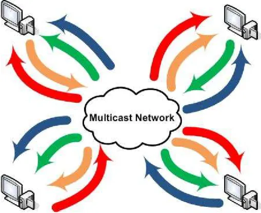
Figure 1 Video conferencing in a Multicast Network... 3
Figure 2 Full Mesh video conferencing... 4
Figure 3 MCU forwarding all flows... 5
Figure 4 MCU forwarding one flow ... 6
Figure 5 Media mixing MCU ... 7
Figure 6 SIP packet schema ... 9
Figure 7 SIP packet with SDP ... 12
Figure 8 Video phone call establishment SIP dialog ... 13
Figure 9 RTP packet schema ... 18
Figure 10 Video conferencing delays ... 19
Figure 11 Secure SIP dialog using TLS ... 22
Figure 12 SIP digest challenge authentication ... 23
Figure 13 Securing the whole SIP message ... 24
Figure 14 SRTP schema ... 25
Figure 15 AES counter-mode ... 26
Figure 16 SRTP HMAC generation ... 27
Figure 17 SRTP crypto context creation... 27
Figure 18 MIKEY operation ... 28
Figure 19 MIKEY PSK key agreement ... 30
Figure 20 MIKEY PKE key agreement ... 31
Figure 21 MIKEY Signed DH key agreement ... 32
Figure 22 SIP and MIKEY ... 33
Figure 23 MCU layer proposed design ... 36
Figure 24 SRTP capable MCU ... 37
Figure 25 Director Functionality... 37
Figure 26 SDP media dealing... 40
Figure 27 Implemented SIP state machine ... 40
Figure 28 Dynamic SRTP key generation ... 42
Figure 29 Packet Reflector orders in a SDP negotiation ... 44
Figure 30 Flow result... 44
Figure 31 MCU operating with SRTP flows ... 45
Figure 32 MCU as a server ... 46
Figure 33 MCU as a caller... 46
Figure 34 MCU re-Inviting operation ... 49
Figure 35 MCU re-Inviting operation with sendonly attributes ... 50
Figure 36 Testbed topology... 52
Figure 37 Flow result... 53
Figure 38 Flow result in a secure scenario ... 55
Figure 39 Alternative testbed... 57
Figure 40 Flow result... 58
1. Introduction
In a global situation, where companies and institutions operate all over the world and Internet is present in almost all countries, video conferencing is becoming an essential tool to communicate people in very far locations. It is a clear example of how technology can be applied to solve real needs of the society.
Nowadays, video conferencing can be used in business meetings, telemedicine or medical councils and even in distant education. To all these reasons can be added that, since video conferences suppress the need to travel in order to have a meeting, it also contributes to environmental preservation-care.
In order to increase the feeling of the participants in a video conference to be in the same room, new media technologies can be used. High Definition video technologies can improve the user experience, since details can be noticed. The quick development underwent by Internet technologies in last years increased the bandwidth available for user applications. This fact, linked with the growth of the SIP protocol and the H.323 specifications in the VoIP environment, has allowed the manufacturers to build simple-to-use video conference solutions.
Finally, the use of Internet to transmit the media of a video conference shows some security issues to be solved. Doctors and businessman of any corporation probably would like to be sure only authorized people can watch and listen the conference, so some security measures must be implemented to protect this information.
2. Background
This section presents a theoretical study about technologies and products involved in secure High Definition video conferencing.
Firstly, current solutions in video conferencing are analyzed. It is also presented the concept of a centralized solution for multi point conferences.
After that, signalling protocols to control media sessions and media issues (basically video coders) are studied.
Finally, security solutions for media and signalling are discussed, making several proposals to provide different security levels to video conferences.
2.1. Video conferencing
A video conference is usually defined as a meeting of three or more people placed in different locations using any technology that enables them to see and to hear each other almost as if they were in the same room.
The difference between a video conference and a video call is the number of participants in the meeting: two people would be considered just a video call (mainly because it can be done as a peer-to-peer call), whereas three or more people would be considered as a video conference.
A video conference could also include file sharing, white board sharing and instant messages, which helps to have the feeling of being in a real meeting. Thanks to all these functionalities, video conferencing is a very valuable tool for telemedicine, distance education and business, because it allows to communicate people at different and very far locations without the need to travel.
2.1.1.
History
The first approach for a video conference was made using two different UHF radio channels to send the signal obtained from television cameras. This system was used in the first space flights by the NASA and some television channels in the 60s and the 70s [1].
Few years after, television channels moved to mobile links to satellites using special trucks for their live connections outdoors. This was a very expensive technology, so it was not common in uses such as education, medicine or business.
For that reason, during the 70s, the American operator AT&T developed the Picturephone, which was a telephone able to send low quality video and a telephone audio channel in a 6Mbps bit rate. Unfortunately, the equipments and the line costs were very high so the system did not succeed [1].
In the 80s, Integrated Services Digital Network (ISDN) links deployed a digital telephony network, so operators started selling few models of videophones. Those devices were used to compress the video and the audio and to transfer that data to another videophone through the digital telephony line [1].
It was in the 90s, with the Internet Protocol (IP) networks deployment and the appearance of new standard based technologies when video calls or video conferencing became popular. Low quality video and audio channels were used as part of most the instant messaging platforms. Also, dedicated and expensive devices were made for big companies, in order to allow their people to meet with no time loose and avoiding travelling costs.
Nowadays, video conferencing is used very often in big corporations, telemedicine and some educational environments. The research efforts in that area are focused on the use of High Definition (HD) video or high quality media, offering secure solutions and the combination of both.
2.1.2.
Videoconferencing architectures
Depending on the way the media flows are treated and sent, several solutions have been proposed in videoconferencing environments through IP networks. Videoconferencing seems to be a perfect scenario to use multicast, since media flows generated by one source must be delivered to several destinations (see Figure 1). Unfortunately, in many situations multicast will not work between users so alternative solutions must be considered in case it is not available [2] [3].
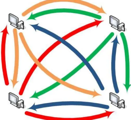
Full Mesh
In this architecture, each participant in a virtual meeting is sending his or her media flows to all other people in the meeting, as shown in Figure 2. It can also be understood as individual video phone calls between all participants in the conference.
The weakness of this architecture is that each participant would need a lot of bandwidth to send the flows to all other participants. Also, a lot of bandwidth would be needed to receive all media flows coming from other participants. These reasons would limit the number of people on a meeting to the number of flows that can be fit in the Internet link bandwidth.
The biggest strength of this solution is that no centralized architecture is needed, so it is inexpensive, no delays are introduced in the communication and all signalling is done as a peer-to-peer communication between the clients. It is clear that this could be a good solution for low quality video and audio flows, but it is unaffordable with high quality or High Definition flows because of their high bit rate.
Figure 2 Full Mesh video conferencing
Forwarding
Another possible solution is to establish a centralized architecture, with a main node receiving all flows and replicating them to all other participants [2] [3] [4]. This central node is called Multipoint Control Unit (MCU) and it simulates a multicast network, since each participant is just sending one flow to the MCU but it could be finally delivered to all other participants. Users could be receiving
several flows too, as if they were in a multicast group with more than one media source.
There are two operational ways to perform the media forwarding, depending if all flows are sent again to all participants or if just one flow is forwarded.
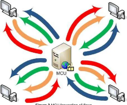
In the first case, the MCU is certainly imitating a multicast network, since the topology will look like as if all participants were in the same multicast group (see Figure 3).
The strength of this possibility is that each participant is only sending his or her media flow once, but it is finally delivered to all other participants. Anyway, all the flows from others must be received, so the download link must be also quite big. However, this situation seems perfect for asymmetric Internet links, such as ADSL.
The biggest weaknesses of this system are the delays added by the central node and that it could become a bottleneck of the system, since it is a centralized element. Nevertheless, the delay can be minimized by using fast software and equipment and high speed lines.
Figure 3 MCU forwarding all flows
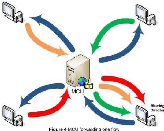
The second possibility using an MCU is to forward only one of the flows received from participants (see Figure 4). This helps to reduce the bandwidth needed to get the flows from other participants, but just allows seeing one of them.
The most practical thing would be that the MCU was able to forward all audio flows and just the video one with the highest volume in the audio channel.
However, this is quite slow because the audio flow must be analyzed, so the delay added by the MCU could be high.
A solution that has been proposed by forwarding-solution developers is to have a meeting director, who is able to switch the media flow forwarded by the MCU. He or she can see and hear media flows coming from all participants, but the other participants just receive the one the director chooses. This is a good solution for chaired meetings with a director giving speech turns.
Figure 4 MCU forwarding one flow
Another smart solution would be to analyze the audio stream and show the one with the highest sound volume.
In some situations, like debates between two people, it would be interesting to forward more than one flow but not all of them. This could be performed the same way is done when forwarding just one.
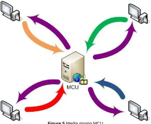
Media mixing
The last architecture presented is also based on a central node to deal with media flows, but this one is not forwarding media as it comes from the participants.
In these systems, the MCU should be able to create a new media flow compounded of all or some of the flows sent by the people in the meeting (see Figure 5). This will allow all participants to see and to hear each others by receiving just one flow.
However, the mixing process could be very slow and the delays added in the MCU process too long for a video conference.
Moreover, thinking about High Definition conferences, it would make no sense for the users to send HD video flows if the MCU is downscaling them to create a new flow, since details will be lost.
Figure 5 Media mixing MCU
2.1.3.
Current solutions
Nowadays, video conferences over IP are very popular, mainly because of the low cost of high speed Internet lines.
On one hand, video phone calls are still made inside of the instant messaging platforms (MSN Messenger, Yahoo! Messenger, AOL IM) or some specific software (NetMeeting, Skype), although some manufacturers are selling IP video phones (D-Link eye2eye videophone).
On the other hand, there are several options for video conference calls. Closed solutions based on specific devices still exist, although most of them are based on open standards for signalling protocols and media transfers (Polycom, Tandberg or Cisco Unified Videoconferencing products). Also, some software solutions are available (NetMeeting).
Even though most of these solutions offer a good security level (some of them use cipher, authentication and integrity standards), none of them is ready to work with high bit rate media flows, such as High Definition flows.
Also, some High Definition systems are present, but they are based on closed and private solutions and often can not work at the same time as secure systems.
2.2. Signalling protocols for Internet conferences
In order to establish a video conference over Internet, a signalling protocol must be used. In this area, lots of solutions have been implemented by manufacturers, but the most interesting ones are those based in open standards.
There are two main standard protocols thought to be used in the establishment of media sessions over an IP network, such as phone calls or conferences: H323 and SIP [5].
2.2.1.
H.323
H.323 is a standardized protocol from the International Telecommunication Union (ITU). Its first version was released in 1996 and several revisions have
been made on it. It was quickly adopted by operators as a signalling protocol used for VoIP and video conferences [5] [6].
Since the companies from the ITU are mostly phone operators and big telecommunications companies, H.323 describes very well defined rules to operate and it is oriented to be used in all kind of networks, like IP, PSTN or ISDN.
However, their main weaknesses are that it is not flexible, it is difficult to provide different services with it and it is a very heavy protocol, what makes it non-scalable.
2.2.2.
The Session Initiation Protocol (SIP)
The Session Initiation Protocol is an application-layer control protocol for creating, modifying and terminating sessions with one or more participants, including multicast sessions [7]. It was defined by the Internet Engineering Task
Force (IETF) in the RFC 2543 from 1996 and it is used in VoIP solutions and
3GPP mobile technology. It was updated in 2002 in the RFC 3261.
SIP can be delivered over any transport-layer protocol, such as UDP, TCP or SCTP, although it is commonly transported over UDP. It is a text-based protocol, as HTTP, so it can easily be read by humans. This make it a little inefficient in comparison to H.323, but at the same time gives it the possibility to interact with other Internet technologies, like web sites (using SIPlets), and reuse components from other IETF protocols, like HTTP or SMTP [7].
As a signalling protocol, SIP does not care about the media transfers, so it is often used together with RTP/RTCP. However, SIP can also be used in Event Subscription and Notification, Session Mobility and Instant Message solutions.
Whereas H.323 is a very well defined protocol with strong rules, the main strength of SIP is its flexibility and that allows developers to easily design new services using it. Also, the SIP philosophy is to give the clients the intelligence, so the network core can be very simple and the system becomes very scalable [5].
SIP Actors
The Session Initiation Protocol is based on the operation of several actors that will exchange messages in order to establish a session. These actors are the ones listed and explained below [2] [5] [7]:
• User Agent Client: applications that generates SIP requests
• User Agent Server: applications that processes SIP requests and generates SIP responses
• User Agent: applications that interact with the final user. They are usually made of a User Agent Client (UAC) to generate requests and a User Agent Server (UAS) to process requests and generate responses.
• SIP Proxy: these elements help to route requests and responses to the current location of the receiver of a message
• SIP Registrar: these elements are a special type of proxy. They are the responsible to inform the callers for the actual location of the users of that domain, by resolving to a network address. All SIP users in the domain which the registrar is responsible for would have to register on them
SIP messages
SIP is based in the message exchange between the initiator of the session and the receiver or receivers. These messages are divided in a first line, a header and a body (see Figure 6) [7].
Figure 6 SIP packet schema
The first line of a SIP message is reserved to indicate the main purpose of the packet, the destination of the message and the protocol version. An example of a first line of a SIP message could be the following:
INVITE sip:[email protected] SIP/2.0
In this example, the caller would be inviting [email protected] to establish a session using version 2 of the SIP protocol.
In the protocol definition, there is a set of SIP methods defined. The most used ones are the following:
• INVITE is used to request the start of a session to another user
• REGISTER is used to get registered into the client’s registrar
• ACK is used to acknowledge the receipt of a message
• BYE is used to end the session
• OPTIONS is used to request client or server capabilities
• CANCEL is used to cancel a request
• INFO is used to exchange control info once the session is established Apart from these messages, there is a code defined for the responses to the messages. It is similar to the code defined for responses in HTTP and is based on a number and an optional explanation sentence [7]:
• Codes 100 to 182: informational messages, such as 100 Trying or
180 Ringing
• Code 200: success message, 200 OK
• Codes 300 to 302: redirection messages, like 301 Moved Permanently
• Codes 400 to 486: client error messages, such as 401 Unauthorized • Codes 500 to 505: server error messages, like 500 Not
Implemented
• Code 600 to 606: global failure messages, as 603 Decline
Also, any message could be added. This is one of the most important features of SIP and what gives its flexibility. By adding new messages, it is possible to perform different behaviours in the User Agents (sending instant messages, sending files, sending XML parameters, …), so then SIP can be used as a signal protocol for lots of applications.
The second parameter in the first line is called the SIP Uniform Resource
Identifier (SIP-URI). This is the identifier of a user or a device and it is like the
phone number in the traditional phone networks or the email address in the email system. Its structure is very similar to email addresses, using @ symbol to separate the user name from the domain name or the network address. The main structure of the SIP-URI would be this:
sip:[user:password@]hostname|ipv4addr|ipv6addr[:port; params]
Some examples of SIP-URIs could be the following:
• sip:[email protected]
• sip:[email protected]:5060
• sip:user:[email protected]
• sip:[email protected];user=Dave
To enable everybody to contact with a SIP-URI, a mechanism to translate a SIP-URI to the current location network address of the user must be performed.
For that reason, every user should register to the SIP registrar of his or her domain.
To find a user given his or her SIP-URI, a client should find first his or her SIP registrar. To achieve this, the process is similar to the one done in SMTP mail exchanges and it usually involves a Domain Name Server (DNS) request to get the SRV entry for that domain. This operation can also be done by a SIP proxy on behalf of the original client.
After the first line of the SIP packet, a structured header of the packet is enclosed. It is very similar to HTTP or SMTP headers and it describes the caller, the callee, the path and the message type. There are 37 different headers and they can be divided into 4 main groups [5] [7]:
• General headers: used both in request and response messages
• Request headers: used in request messages to add extra information
• Response headers: used in response messages to add extra information
• Entity headers: indicates the length and the content type in the body of the message
The most important and most used headers are explained below:
• Via: indicates the path (SIP proxies) the message took to arrive to the destination
• Max-Forwards: indicates the number of hops the message can do before to arrive to destination. Each proxy server that forwards this message would decrease by one this parameter
• To: indicates the name and the SIP-URI of the destination of the message
• From: indicates the name and the SIP-URI of the source of the message
• Call-ID: unique identification number of the session
• Command-sequence: sequence number of the message and SIP method
o Incremented by one for each new message
o The same number for the responses to a message
• Subject: indicates the subject of the session established
• Contact: indicates the SIP-URI to contact directly the source of the message
• Content-type: indicates the type of content in the message body
• Content-length: indicates the length of the body of the message
• Accept: indicates if the message body is accepted by the client
• Accept language: indicates the preferred language of the user to receive messages
• Date: time of the first request
• Encryption: indicates the preferred algorithm to encrypt the body of the messages
• Require: indicates the functionalities the client needs to be performed to accept the session
• Supported: indicates the features supported by a server
• Timestamp: used by the clients to calculate the round trip time delay Finally, a SIP message can also include a body. It is optional and it usually carries information about the session established or non-SIP parameters to be exchanged.
Session Description Protocol (SDP)
In order to use SIP to establish a media session (i.e. a phone call), it is necessary to agree upon parameters for the session. The caller and the callee must agree which CODEC and which protocols to use, where to send the media flows and where to receive them.
These parameters are not agreed in the SIP message exchange, so another protocol should be used in the SIP message body to do so (see Figure 7). This protocol is the Session Description Protocol (SDP), which is another IETF protocol designed to define media session initialization parameters [8] [9].
Figure 7 SIP packet with SDP
Using SDP, participants can define information related to the type of media (audio, video, …), the CODEC (MPEG, PCM, GSM, …), the transport protocol (UDP, RTP, SCTP, …) and port numbers.
Nowadays, the protocol is described in the RFC 4566 and it defines the following list of attributes to define media sessions:
Session description
• v: protocol version
• o: originator and session identifier
• s: session name
• i: extra session information
• u: URI of description
• e: email address
• p: phone number
• c: connection information
• b: bandwidth information
• z: time zone adjustments
• a: session attribute Time description
• t: time the session is active
• r: repeat times Media description
• m: media name and transport address
• i: media title • c: connection information • b: bandwidth information • k: encryption key • a: media attributes SIP dialog
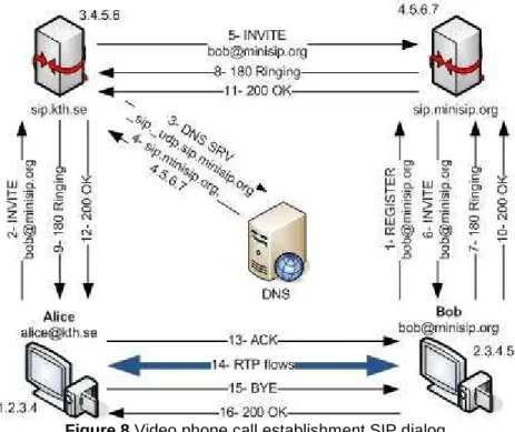
As said above, SIP is a protocol based in the message exchange between SIP User Agents in the clients. Attending to this and taking into account all explained about SIP, an example of a SIP dialog to establish a video phone call is presented.
Imagine two users, Alice and Bob, with their SIP-URIs, [email protected] and
[email protected]. Alice wants to make a video phone call to Bob and she knows about Bob’s SIP-URI but not about his IP address, his location nor his SIP Proxy Registrar. The dialog to establish a call will be the one shown in Figure 8.
Figure 8 Video phone call establishment SIP dialog
• Message 1: Bob is registering in the SIP Proxy Registrar responsible for the domain minisip.org, which is sip.minisip.org. The content of the SIP message would be this:
REGISTER sip:sip.minisip.org SIP/2.0
Via: SIP/2.0/UDP 2.3.4.5:5060 From: sip:[email protected]
Contact: Bob <sip:[email protected]:5060> CSeq: 1 REGISTER
Call-ID: [email protected] Expires: 7200
• Message 2: when Alice wants to contact Bob, she sends an INVITE message through her SIP Proxy. This message contains an SDP message in the body, in order to offer Bob several options to establish the media session.
INVITE sip:[email protected] SIP/2.0
Via: SIP/2.0/UDP 1.2.3.4:5060 From: sip:[email protected] To: sip:[email protected] Call-ID: [email protected] CSeq: 1 INVITE Content-type: application/sdp v=0
s=Video phone call [email protected] c=IN IP4 1.2.3.4 t=0 0 m=audio 10000 RTP/AVP 0 8 a=rtpmap:0 PCMU/8000 a=rtpmap:8 PCMA/8000 m=video 10001 RTP/AVP 34 a=rtpmap:34 H263/90000
In this SDP, Alice is offering Bob to use either PCMU or PCMA audio codec in her UDP port 10000 over RTP and H263 video codec in her UDP port 10001 also over RTP for the video phone call.
• Message 3: since Alice SIP proxy (sip.kth.se) does not know about Bob’s SIP Proxy, it makes a DNS Request in order to get its address. The proxy would ask for the SRV entry and it would indicate to find a SIP and UDP capable server.
• Message 4: the DNS response would include the name of the SIP proxy for minisip.org domain as well as its IP address.
• Message 5: now, sip.kth.se can forward the Alice INVITE message to sip.minisip.org, adding a Via header in the SIP header:
INVITE sip:[email protected] SIP/2.0
Via: SIP/2.0/UDP sip.kth.se:5060 Via: SIP/2.0/UDP 1.2.3.4:5060 From: sip:[email protected] To: sip:[email protected] Call-ID: [email protected] CSeq: 1 INVITE Content-type: application/sdp v=0
s=Video phone call [email protected] c=IN IP4 1.2.3.4 t=0 0 m=audio 10000 RTP/AVP 0 8 a=rtpmap:0 PCMU/8000 a=rtpmap:8 PCMA/8000 m=video 10001 RTP/AVP 34 a=rtpmap:34 H263/90000
• Message 6: the INVITE message would be finally delivered to Bob by his SIP Proxy, adding another Via header:
INVITE sip:[email protected] SIP/2.0
Via: SIP/2.0/UDP sip.kth.se:5060 Via: SIP/2.0/UDP 1.2.3.4:5060 From: sip:[email protected] To: sip:[email protected] Call-ID: [email protected] Cseq: 1 INVITE Content-type: application/sdp v=0
s=Video phone call [email protected] c=IN IP4 1.2.3.4 t=0 0 m=audio 10000 RTP/AVP 0 8 a=rtpmap:0 PCMU/8000 a=rtpmap:8 PCMA/8000 m=video 10001 RTP/AVP 34 a=rtpmap:34 H263/90000
• Messages 7, 8 and 9: Bob’s User Agent would send a 180 Ringing to Alice in order to inform her User Agent the INVITE message was received. This message is going to be forwarded back to Alice through the SIP Proxies, each one of them adding a Via Header.
SIP/2.0 180 Ringing Via: SIP/2.0/UDP 2.3.4.5:5060 From: sip:[email protected] To: sip:[email protected] Call-ID: [email protected] Cseq: 1 INVITE Content-length:0
• Messages 10, 11 and 12: as soon as Bob picks up the phone, his User Agent would send a 200 OK response to Alice. This message is also going to be delivered through the proxies, since Bob does not know yet Alice’s address. SIP/2.0 200 OK Via: SIP/2.0/UDP 2.3.4.5:5060 From: sip:[email protected] To:sip:[email protected] Call-ID: [email protected] Cseq: 1 INVITE Content-type: application/sdp v=0
s=Video phone call [email protected] c=IN IP4 2.3.4.5 t=0 0 m=audio 20000 RTP/AVP 0 8 a=rtpmap:8 PCMA/8000 m=video 20500 RTP/AVP 34 a=rtpmap:34 H263/90000
In the SDP message, Bob chooses to use PCMA over RTP in his 20000 UDP port for the audio flow and H263 over RTP in his 20500 UDP port for the video flow.
• Message 13: when Alice gets the 200 OK message from Bob, she sends an acknowledgement for this message to tell Bob she accepts the parameters Bob chose. At this moment and thanks to the Via headers, Alice knows Bob’s location, so this message is sent directly to Bob.
ACK sip:[email protected] SIP/2.0
Via: SIP/2.0/UDP 1.2.3.4:5060 From: sip:[email protected] To: sip:[email protected] Call-ID: [email protected] Cseq: 1 ACK Content-length: 0
If Alice did not accept Bob’s SDP offer (either for the CODEC, the port or anything else), she would send a CANCEL message instead. Then, the connection would be closed.
• Message 14: Alice and Bob will be sending each other 2 RTP flows containing audio and video information. They should use the CODECs and the ports they agreed in the SIP dialog, thanks to the SDP protocol.
• Message 15: when the video phone call ends, Alice would hang up and media flows would stop sending. At this moment, her User Agent is going to send a BYE message to Bob’s User Agent, so it notices the call is over.
BYE sip:[email protected] SIP/2.0
Via: SIP/2.0/UDP 1.2.3.4:5060 From: sip:[email protected] To: sip:[email protected] Call-ID: [email protected] Cseq: 345 BYE Content-length: 0
• Message 16: finally, Bob would accept the end of the call by sending a
200 OK message to Alice. SIP/2.0 200 OK Via: SIP/2.0/UDP 2.3.4.5:5060 From: sip:[email protected] To: sip:[email protected] Call-ID: [email protected] Cseq: 345 BYE Content-length: 0
2.3. Dealing with media in video conference environments
Once the signalling protocol agrees the parameters to establish a media session, data flows containing audio, video or other kind of information can be sent by participants.
However, it is necessary to define some protocols to allow participants to read correctly these media flows.
2.3.1.
Real-time Transport Protocol (RTP)
The Real-time Transport Protocol (RTP) is a standardized packet format designed to deliver media contents (mostly video and audio, but also images) over an IP network [10]. It was first defined in 1996 as RFC 1889, which was replaced by RFC 3550 in 2003.
It was originally thought as an add-on for the UDP protocol in media environments, although it can be also delivered over a TCP layer. It has no defined port to be delivered, so it is usually delivered in the wide area of non-defined ports. However, it is said in the standard that RTP must use an even port and the Real-time Transport Control Protocol (RTCP) use the next odd port.
An RTP packet is divided into a 12-bytes header and a payload (see Figure 9). The payload would carry the data of the packet and in the header the following information is provided [5]:
• RTP Version [V] (2 bits): indicates the version of the protocol. Current version is 2
• Padding [P] (1 bit): indicates if there is extra information at the end of the packet, in order to exactly fit on an 8 bit alignment
• Extension [X] (1 bit): indicates if any extension of the protocol is used in the packet
• Contributors [NCSRC] (2 bits): indicates the number of contributors to that session. It is used to read the CSRC optional headers
• Marker bit [N] (1 bit): it is used to inform the application that something special is in that packet. Usually is always off in audio streams and 1 in video packets containing the last information of a frame
• Payload type [PT] (7 bits): identifier of the type of data in the payload of the packet. Usually it is an identifier of the codec used in the media transported, defined in the RFC 3551
• Sequence number [SN] (8 bits): sequence numbers increased by one at each packet
• Timestamp [TMP] (16 bits): time of the acquisition of the first sample carried by the packet
• Synchronization source identifier [SSRC] (16 bits): identifier of the source of the packet
• Contributing source identifier [CSRC] (16 bits): identifier of the contributors to the media session. It is optional and it will be one for each participant when the media goes through a mixer
Figure 9 RTP packet schema
The RTCP protocol was designed as a brother protocol of RTP in the same RFC 3550. It is usually transmitted periodically together with an RTP flow and provides quality of service feedback and control information to the source and
the receiver of the media flow, like timestamps linking to Network Time Protocol (NTP) times or changing CODEC requests.
2.3.2.
Delays and Video coders
In a video conference, video flows should be treated in a special way. In these environments the delay must be as small as possible, in order to give the participants the feeling that they are in front of each other.
Attending to the interactivity ITU recommendation, the maximum delay between each part should not be longer than 150ms (Round Trip Time <= 300ms). This means that a participant should see and listen what happened in the other participants’ rooms 150ms before. This is really difficult to achieve with nowadays technologies if one consider using HD video, but gives the idea on how the delay should be considered.
To measure the delay, several times must be taken into account: acquisition time, compression time, packetizing time, network transmission time, unpacketizing time, decompression time and jitter-control display buffer time (Figure 10).
Figure 10 Video conferencing delays
Regarding to this time schema, it is easy to realize that the less is the compression/decompression time, the less is the total delay of the system. So then, it is a good idea to use media CODECs that do not take too much time to compress media or even not to compress it, always trying to compromise compression time and network transmission time.
Digital Video (DV)
This format of video is the one used by most of the domestic video cameras. It consists in raw PAL/NTSC images usually obtained through the Firewire interface (IEEE 1394). It mixes in a single 25Mbps flow video and audio signals. Since no compression is applied and the output bit rate seems quite reduced, it could be valid for a first approach in video conferencing. However, having the
analyzed to decide which flow is being showed. Moreover, the quality of the video flow is just PAL/NTSC, which means is no High Definition.
High Definition Digital Video (HDV)
This format is the High-Definition evolution of the Digital Video format. It offers the possibility to fit in a 25Mbps flow an audio and a HD video flow [12]. However, MPEG-2 compression is applied, so the delay is increased.
Because of the compression introduced by HDV cameras, this seems not to be a right format for High-Definition video conferencing.
MPEG4/H.264
The MPEG4 or H.264 codec is the newest video coder from the Moving
Pictures Experts Group (MPEG) and the ITU. It uses several techniques to
compress the image flow, such as backward and forward movement prediction, wavelet transform (like JPEG200 standard) and adaptive quantifiers.
These techniques make possible to obtain high-quality results with a contained bit rate, which is what is looked for High Definition video conferencing.
This standard was designed to be delivered through a packet network, so it was defined also as an RTP encapsulation for it in order to improve the efficiency. Most of the current commercial video conferencing solutions offered by manufacturers support and take advantage of this standard, usually implementing a proprietary profile of it. However, and specially because of the delay introduced by the forward movement prediction used in most of H.264 implementations, the delay introduced when using them is long enough not to be used in video conferencing environments.
Several studies are being done in this area at the moment, most of them focused on reducing the compression time avoiding the forward movement prediction.
2.4. Security issues
Until this part of the document, several protocols and solutions have been studied. However, no security aspects have been taken into account.
There are several ways to secure these protocols and different security levels for each one, so they must be analyzed.
2.4.1.
Security definitions
First of all, it is necessary to define what means that the different subjects that can be secured in a communication through a packet network.
Confidentiality
In a packet switched network and especially in Internet, there is no possibility to control the path our packets will take. This means that anybody could be listening on the network and looking at the information inside our packets or the packets sent to us.
Confidentiality means that only authorized people can read the information in a message. This is usually achieved by encrypting all the information transferred through the network.
Integrity
As said above, there is no chance to control our packets along their path to the destination. Anybody could modify the information on them and the receiver would not notice.
To avoid that, some procedures must be done in order to ensure that the receiver is getting exactly what the sender sent, without modifications. This is often done by hash codes of some information the sender and the receiver know and some information in the message.
Authentication and non-repudiation
Authentication is needed in order to make sure somebody is who he or she claims to be. It is absolutely necessary to be sure the receiver of the information is the right one to provide full-secured communications.
Usually, authentication is merged with non-repudiation. This means that a party in a dispute cannot refuse he or she did something
Both properties are usually achieved by a digital signature procedure, using a
Public Key Infrastructures (PKI), and also provide integrity.
Availability
It is important for a service to be available for as much time as possible. In order to avoid down times, it is necessary to think about different techniques to prevent Denial of Service (DoS) attacks.
Public Key Infrastructure
A Public Key Infrastructure is a set of technologies, policies and procedures that allow the secure use of cryptographic methods, such as ciphering or digital signature [13].
Usually, a PKI is based on the operation of one or more Certificate Authorities (CAs). These authorities are responsible of several user certificates and can assure to anybody that who is using a certificate is who he or she says. However, it is necessary to trust the CA.
A certificate contains a pair of public-private keys that can be used in asymmetrical cryptography procedures, like digital signature or data authentication.
2.4.2.
Securing SIP
Although of its diverse advantages, SIP shows a severe disadvantage since it does not provide any security measure to secure the protocol itself. To do so, it relies on other generic protocols, such as Transport Layer Security (TLS) or
IP-Security (IPSec) [7].
Several things can be protected in a SIP communication, so it is important to offer solutions for all the issues.
Securing communications
As seen in the SIP dialog above, SIP was designed as a non-encrypted protocol, so its messages are transmitted as plain text. This is a very important security problem because anybody could see user activities, such as in or out calls or instant messages sent using SIP. To solve this, SIP offers the solution to use TLS, establishing hop by hop TLS links between all nodes in the dialog [14] [17].
In order to require this security measure, a new SIP-URI has been created, the SIPS-URI. The format of the new address is the one below:
sips:[user:password@]hostname|ipv4addr|ipv6addr[:port ;params]
By using a SIPS-URI, intermediate nodes will be forced to establish secure links between them using TLS [7]. All connections will be then secured, except the one between the destination proxy and the destination user, which could be secured or not depending on the policy of the SIP proxy [14]. If one of the hopes can not be secured, the connection should fail.
Using the example of the SIP dialog above, the blue areas over SIP messages in Figure 11 would be the TLS secured connections:
Nevertheless, before creating the TLS links between the proxies, they will need to authenticate each other, so a PKI will be needed. Since it could be useful to provide security in other aspects of video conferencing, the use of a PKI seems to be a logical solution.
Securing register
When a user is registering to his or her SIP Registrar, some security measures must be taken into account. The SIP Registrar must assure the user is who he or she claims to be by authenticating them before they can register.
To do so, SIP offers two authentication schemas, similar to the ones offered by HTTP:
• Basic authentication: this schema is very weak because it is based on sending as clear text user and password. For this reason, it has been deprecated.
• Digest challenge: the user tries to get registered in the SIP Registrar with no authentication and the server denies the request and attaches a nonce to the CANCEL message [7]. Then, the user would make another REGISTER request, by adding to the packet the result of the MD5 hash function over the nonce, the user and the password. If everything goes right, the user gets registered (see Figure 12).
Figure 12 SIP digest challenge authentication
Though it seems the digest challenge method could be enough, the user is not authenticating the server, so a fake server could impersonate him or her. The solution for that is again the use of a PKI to authenticate the client and the server and the TLS protocol to protect network communications.
Securing the body message
Another possibility would be to secure only the body of the SIP messages. This will not protect the signalling information but SDP messages or any other information contained in the body message (like instant messenger texts) could be at least protected.
SIP specifies the use of the Secure/Multipurpose Internet Mail Extension (S/MIME) to provide confidentiality, integrity and authentication to the body of SIP messages by using a PKI [13] [14] [15].
Securing the whole SIP message
By using S/MIME it is also possible to protect the whole SIP packet, including the headers. This technique copies the whole SIP message (headers and body) inside the body (Figure 13) [16] [17].
Then, S/MIME is used to provide confidentiality, integrity and authentication to the body of the SIP message, which contains the whole original packet. The receiver of the message should decrypt the body and compare the copied message inside with the whole packet.
If both messages are equal, no changes had been made on them. However, if not, some changes had been made in the packet.
This system should take into account that some proxies could add headers to the SIP message, like Via headers. This makes it difficult to be implemented and adds computational complexity to the SIP message dealing process.
Figure 13 Securing the whole SIP message
Another problem of this procedure is that the resultant UDP message would probably be bigger than the network MTU so UDP packets will be fragmented. This is a problem because the standard configuration of the most spread SIP proxy (SIP Express Router) [26] discards all fragmented packets. A solution for that could be using a reliable transport protocol (such as TCP or TLS) to deliver these messages, as the standard says.
2.4.3.
Securing Media: Secure RTP (SRTP)
There are several options to secure the content of the media flows, depending of which level of the TCP/IP stack is protected.
One option is to use IPSec tunnels between participants [18], which is a very heavy solution because it is protecting the network layer. Another possibility is to use Secure RTP to protect the RTP flows carrying media, which is a smart solution for communications over Internet because only application layer is protected.
Attending to previous studies in this area [16] [18], the use of SRTP seems more convenient for video conferencing environments, since it is a close environment to VoIP.
The Secure Real-time Transport Protocol (SRTP) is a profile to secure the RTP media transport protocol specified by the proposed standard in the RFC 3711 [19].
The protocol is thought to provide confidentiality, authentication and integrity to the packets of an RTP flow, although only encryption is mandatory. The security is applied to the packet as Figure 14 shows.
Figure 14 SRTP schema
Several security issues, such as confidentiality, authentication and integrity, can be solved by using SRTP to protect RTP media flows.
Confidentiality: AES
In the SRTP draft, confidentiality is achieved by encrypting only the payload of the RTP packets. The encryption is provided by the Advanced Encryption
Standard (AES) algorithm used in the cipher-stream mode, instead of the block
cipher performed usually by AES [13].
The use of AES instead of some other algorithms is not a coincidence. The main reason to choose AES in front of other algorithms is its low computational requirements and that it is often implemented in hardware. These characteristics allow this algorithm to be used in low computational devices [14], such as mobile phones or PDAs, and give it the possibility to encrypt high bit rate flows using powerful machines.
AES describes three different procedures to work under the cipher-stream mode, but only two of them are used in SRTP:
• NULL cipher: it can be used to disable encryption, when authentication and integrity protection are needed, but not confidentiality.
The operation of this mode is very simple: it just copies the input to the output, with no changes in the payload of the RTP packet.
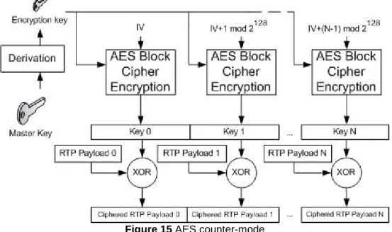
• Segmented Integer Counter Mode: this mode is based in typical counter mode behaviour, using one-time-pad keys to cipher the plaintext. The main advantage of this mode is that one-time-pad keys can be pre-computed and then used in the XOR with the plaintext [13].
This is the default algorithm for SRTP and it uses a 128 bits default encryption key and a 112 bits default session salt key.
In the below schema (Figure 15), it is shown how the default AES Block Cipher is used in counter-mode. The Initialization Vector (IV in the figure) depends on the source identifier (SSRC), the packet index (Sequence Number) and the salting key.
Figure 15 AES counter-mode
Authentication and Integrity: HMAC
Although the RTP packets were ciphered, anybody in the network could manipulate them or even replace them. This could be a big security hole, because reply attacks can be done against a receiver, making impossible to him or her to receive any media.
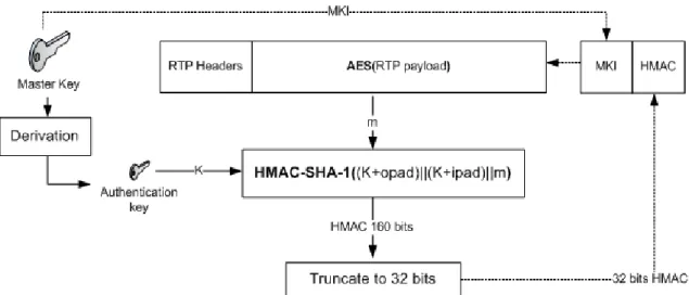
To solve these issues, authentication and integrity protection must be provided. This is achieved by a keyed-Hash Message Authentication Code (HMAC) based on a Security Hash Algorithm 1 (SHA-1) hashing function. This function returns a Message Authentication Code (MAC), which is added to the RTP packet with a ciphered payload.
A keyed-Hash Message Authentication code is obtained applying a hash function to the content to be protected, an authentication key and two defined padding (opad, ipad) [13]. Note that the hash is applied after the encryption is done and it protects also the RTP headers.
The default authentication key should be 128 bits and the HMAC-SHA-1 algorithm will generate a 160-bit hash code. In SRTP this hash code is truncated to the last 32 bits (4 bytes) [19], in order not to add too much overhead to the media flow (Figure 16).
Finally, a 4-byte Master Key Identifier is also added to the packet, in order to inform the receiver which crypto context (encryption key, authentication key and salt key) was used to protect that packet (Figure 16).
Figure 16 SRTP HMAC generation
SRTP cryptographic issues
As stated, SRTP uses a master key to obtain the other keys used to protect the RTP packets, but the draft says nothing about how to share this master key between the source and the destination.
In order to get an encryption key, an authentication key and a salt key from the same master key, a derivation function is used to generate this crypto context (Figure 17) [19]. By this way, only a master key needs to be exchanged.
Moreover, SRTP could become insecure if the same key is used to cipher more than 248 packets, a number fixed because of the rollover counter and the sequence number lengths. With this amount of ciphered data, the possible attacker could obtain information and break the cryptographic session. In order to avoid this, a re-keying protocol to generate a new crypt context is needed too.
2.4.4.
Key Agreement: MIKEY
There are some existing key agreement implementations, such as the Internet
Security Association and Key Management Protocol (ISAKMP) framework and the Internet Key Exchange (IKE) protocol [14]. Both of them provide several levels of security.
However, there is a very specific option for protecting multimedia exchanges: the Multimedia Internet Keying (MIKEY) [20]. It is been revealed as the best option when using SIP to establish secured multimedia sessions [14] [18].
The purpose of MIKEY is to exchange cryptographic parameters in the media negotiation process. This, when using SDP over SIP to establish media sessions, means that MIKEY should be able to perform a mutual authentication and agree a master key in just one roundtrip.
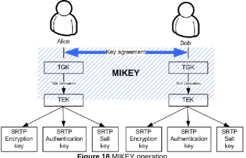
MIKEY defines a way to exchange a master key, called Transport Generation Key (TGK). From this TGK, MIKEY is able to get a Transport Encryption Key (TEK), which will be the one used as the SRTP master key (see Figure 18) [14] [20]. The protocol also provides a mechanism to exchange other security parameters.
Figure 18 MIKEY operation
Solved security issues
Several security issues can be protected by using MIKEY. The most important ones are the following:
• Mutual authentication: it allows the authentication of both parts in the media session by the use of a challenge/response scheme.
To fit the challenge/response scheme in the offer/answer model, basically reducing by one the number of exchanged messages, MIKEY uses timestamps as challenges.
Using timestamps in combination with an authentication key, allows the participants to verify the identity of each other.
• Replay protection: it prevents the use of the same timestamp to authenticate for twice.
When a timestamp is received, it is stored locally and every new MIKEY message should use a later timestamp than the stored ones.
• Perfect forward secrecy: using Diffie-Hellman agreement schema, it is possible to assure that even if a private key is revealed, there is no chance to compromise the keys used in a crypto session.
This is possible because a completely new and random TGK is agreed every time a connection starts.
Key agreement types
Depending on the computational resources and the authentication procedures available, MIKEY describes three types of key agreements [20]:
• Pre-shared key (PSK): in this type of agreement, Alice and Bob must share a secret in advance.
Assuming K as the pre-shared secret, RAND as random generated string, ID as the user identifier, constant1 and constant2 as two well-known byte strings and f() as a pseudo-random function defined in the MIKEY draft, the key agreement would work as shown in Figure 19.
Figure 19 MIKEY PSK key agreement
Alice generates an encryption key and an authentication key. Then she sends a Timestamp, a random string, her user identifier, the MIKEY TGK key encrypted with the generated encryption key and a MAC to protect the whole message using the generated authentication key.
Then, Bob generates the encryption key and the authentication key with the parameters he received from Alice. These keys should be the same as Alice generated, since the parameters used to generate them are the same. So then, Bob can decrypt the TGK key and can check the MAC Alice sent.
After that, Bob answers with a Timestamp, his user identifier and a MAC to protect the message with the generated authentication key.
Finally, Alice checks the MAC to make sure that Bob is the one who sent this message.
• Public-key encryption (PKE): in this type of agreement, Alice and Bob must have each a pair of public/private keys. It is also needed a PKI in order to validate user keys in front of other users.
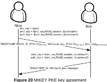
Assuming rand() as a random function that generates a random byte stream, RAND as random generated string, ID as the user identifier, constant1 and constant2 as two well-known byte strings and f() as a pseudo-random function defined in the MIKEY draft, the key agreement would work as shown in Figure 20.
Figure 20 MIKEY PKE key agreement
Alice generates an envelope key with a random function. With the result of that function, an encryption key and an authentication key are generated. Then she sends a Timestamp, a random string, her user identifier, the MIKEY TGK key encrypted with the generated encryption key, a MAC to protect the whole message using the generated authentication key and the envelope key encrypted with Bob’s public key. Then, Bob decrypts the envelope key using his private key. With the clear envelope key, he generates the encryption key and the authentication key with the other parameters he received from Alice. These keys should be the same as Alice generated, since the parameters used to generate them are the same. So then, Bob can decrypt the TGK key and can check the MAC Alice sent.
After that, Bob answers with a Timestamp, his user identifier and a MAC to protect the message with the generated authentication key.
Finally, Alice checks the MAC to make sure that Bob is the one who sent this message.
• Signed Diffie-Hellman (DH): in this type of agreement, Alice and Bob must have each a pair of public/private keys. It is also needed a PKI in order to validate user keys in front of other users and complicate man-in-the-middle attacks, since the attacker would need both Alice an Bob private keys.
Figure 21 MIKEY Signed DH key agreement
Alice generates a random number (x) and sends to Bob a Timestamp, a random byte stream, her user identifier or her certificate, gx mod p, a set of parameters used in the Diffie-Hellman algorithm (basically g and p, defined by a DH_group identifier) and a signature of the message.
Bob generates a random number (y) and answers Alice with a Timestamp, his user identifier or his certificate, gy mod p, gx mod p, the DH_group and a signature of the whole message.
Then, both Alice and Bob can calculate a TGK as gxy mod p. This TGK is generated randomly, so that is why is said that Signed Diffie-Hellman key exchange preserves the perfect forward secrecy, since a new key agreement would generate a completely different TGK [13] [20].
MIKEY in the SIP dialog
One of the main design goals of MIKEY is to fit the key agreement in the media negotiation process, usually done by SIP. The reason why MIKEY should perform the key agreement and the mutual authentication in just one roundtrip is that the SIP call establishment is done in just one roundtrip.
To achieve that, MIKEY key agreement is performed in the INVITE transaction, by adding a new SDP attribute: key-mgmt. This attribute can be set as a session attribute or as a media attribute (see Figure 22) [14].
In the first case, the exchanged TEK will protect all the streams agreed in that session. In the second, a TEK will be exchanged for every flow described and it will be used only to protect only media in that flow.
Figure 22 SIP and MIKEY
In case re-keying is needed, it should be performed by a RE-INVITE
transaction, conducted the same way as the INVITE transaction did.
Dealing with non-secured SIP UAs should also be considered. If a secured UA invites a non-secured UA, the latter is going to omit the key-mgmt attribute in the SDP of the 200 OK message. In that case, the first UA should give the user the option to fall back to an unsecured session initiation (adding another SDP media descriptor in the INVITE message) or to cancel the communication. In the last case, when the callee UA does not accept a non-secure call and the caller policy is do not accept unsecured calls, the receiver could suffer from ghost ringing. Since the 200 OK message is not sent until the callee accepts the call, he doesn’t know if Alice will reject the non-secure session and close the establishment.
The solution to this problem is achieved by using the 1XX SIP responses, provisional responses, to carry the MIKEY response. If the 180 Ringing is used to carry the MIKEY response, the ringing delay could be big, since the callee should process all the crypto session. The solution for that is to use a
183 Session in Progress message, sent after the 180 Ringing but before the 200 OK [16].
3. Background study conclusions
After looking at the state of the art of several technologies linked to the area of this study, several conclusions in the different subjects covered can be proposed.
3.1. Video conferencing
Looking at the current video conference solutions, their problems and some solutions proposed in other studies and the lack of multicast capabilities of most networks, I conclude that a Multi-point Conference Unit is nowadays the best option for video conferencing over Internet.
This system allows the users to send their media flows just once, but these are finally delivered to all other participants in the video conference.
However, most of the commercial solutions are based in proprietary systems integrated in dedicated devices. Although most of them use standard protocols (such as H.323 and SIP), solve some security issues and can deal with High Definition media, they are closed solutions.
Also, it is necessary to work in the video CODEC issue in order to minimize the delay introduced in the compression process.
Finally, the need of a High Definition video conference system comes up to give the user the feeling he or she is in a real meeting with other participants. Adding other capabilities such as sharing files or digital shared blackboards could really make the difference in front of traditional video conference systems.
3.2. Signalling protocol
In this study I dealt with the signalling of a media session establishment, looking at the two main protocols used for that, H.323 and SIP.
After my analysis, I come to the conclusion that because of its flexibility and its simplicity, SIP is the right protocol to use in the development of a new video conference environment.
Moreover, SIP offers several options to secure the signalling messages and to perform user authentication, even though it is done using other protocols, and the possibility to establish a secure media session using SRTP and MIKEY.
3.3. Security
Several studies [18] show that using SRTP is the best option to secure a media session. This option does not add too much overhead and the security standards used on it are quite fast. Also, security is added at the application layer and can be platform-cross, since other options such as IPSec are usually linked to the operating system.
These reasons make me think that SRTP should be a very good solution for video conferencing, where minimizing the delays is one of the most important issues to solve. Also, thinking about High Definition or high quality media flows and their high bit rate, reducing the overhead is also important in order to save network bandwidth.
SRTP needs an external mechanism to perform the key exchange, and previous studies at TSLab were focused on the use of MIKEY to do so.
Since MIKEY is thought to be used over SIP and I stated that SIP is the best option for video conference signalling, I see no reason not to use also MIKEY as the exchange mechanism for SRTP master keys.