72E-124801-05 Revision A March 2011
© 2011 Motorola Solutions, Inc. All rights reserved.
No part of this publication may be reproduced or used in any form, or by any electrical or mechanical means, without permission in writing from Motorola. This includes electronic or mechanical means, such as photocopying, recording, or information storage and retrieval systems. The material in this manual is subject to change without notice.
The software is provided strictly on an “as is” basis. All software, including firmware, furnished to the user is on a licensed basis. Motorola grants to the user a non-transferable and non-exclusive license to use each software or firmware program delivered hereunder (licensed program). Except as noted below, such license may not be assigned, sublicensed, or otherwise transferred by the user without prior written consent of Motorola. No right to copy a licensed program in whole or in part is granted, except as permitted under copyright law. The user shall not modify, merge, or incorporate any form or portion of a licensed program with other program material, create a derivative work from a licensed program, or use a licensed program in a network without written permission from Motorola. The user agrees to maintain Motorola’s copyright notice on the licensed programs delivered hereunder, and to include the same on any authorized copies it makes, in whole or in part. The user agrees not to decompile, disassemble, decode, or reverse engineer any licensed program delivered to the user or any portion thereof.
Motorola reserves the right to make changes to any software or product to improve reliability, function, or design.
Motorola does not assume any product liability arising out of, or in connection with, the application or use of any product, circuit, or application described herein.
No license is granted, either expressly or by implication, estoppel, or otherwise under any Motorola, Inc., intellectual property rights. An implied license only exists for equipment, circuits, and subsystems contained in Motorola products.
MOTOROLA, MOTO, MOTOROLA SOLUTIONS and the Stylized M Logo are trademarks or registered trademarks of Motorola Trademark Holding, LLC and are used under license. All other trademarks are the property of their respective owners.
This media, or Motorola Product, may include Motorola Software, Commercial Third Party Software, and Publicly Available Software. The Motorola Software that may be included on this media, or included in the Motorola Product, is Copyright (c) by Motorola, Inc., and its use is subject to the licenses, terms and conditions of the agreement in force between the purchaser of the Motorola Product and Motorola, Inc.
The Commercial Third Party Software that may be included on this media, or included in the Motorola Product, is subject to the licenses, terms and conditions of the agreement in force between the purchaser of the Motorola Product and Motorola, Inc., unless a separate Commercial Third Party Software License is included, in which case, your use of the Commercial Third Party Software will then be governed by the separate Commercial Third Party License.
The Publicly Available Software that may be included on this media, or in the Motorola Product, is listed below. The use of the listed Publicly Available Software is subject to the licenses, terms and conditions of the agreement in force between the purchaser of the Motorola Product and Motorola, Inc., as well as, the terms and conditions of the license of each Publicly Available Software package. Copies of the licenses for the listed Publicly Available Software, as well as, all attributions, acknowledgements, and software information details, are included below. Motorola is required to reproduce the software licenses, acknowledgments and copyright notices as provided by the Authors and Owners, thus, all such information is provided in its native language form, without modification or translation. The Publicly Available Software in the list below is limited to the Publicly Available Software included by Motorola. The Publicly Available Software included by Commercial Third Party Software or Products, that is used in the Motorola Product, are disclosed in the Commercial Third Party Licenses, or via the respective Commercial Third Party Publicly Available Software Legal Notices.
Publicly available software list:
Name: Regular Expression Evaluator Version: 8.3
Description: Compiles and executes regular expressions
Software Site: http://www.freebsd.org/cgi/cvsweb.cgi/src/lib/libc/regex/
Source Code: No Source Distribution Obligations. Motorola will not provide nor distribute the Source Code for the Regular Expression Evaluator.
License: BSD Style License © 1992 Henry Spencer.
© 1992, 1993 The Regents of the University of California. All rights reserved.
This code is derived from software contributed to Berkeley by Henry Spencer of the University of Toronto. Redistribution and use in source and binary forms, with or without modification, are permitted provided that the following conditions are met:
1. Redistributions of source code must retain the above copyright notice, this list of conditions and the following disclaimer.
2. Redistributions in binary form must reproduce the above copyright notice, this list of conditions and the following disclaimer in the documentation and/or other materials provided with the distribution.
3. All advertising materials mentioning features or use of this software must display the following acknowledgement: This product includes software developed by the University of California, Berkeley and its contributors.
4. Neither the name of the University nor the names of its contributors may be used to endorse or promote products derived from this software without specific prior written permission.
THIS SOFTWARE IS PROVIDED BY THE REGENTS AND CONTRIBUTORS ``AS IS'' AND ANY EXPRESS OR IMPLIED
WARRANTIES, INCLUDING, BUT NOT LIMITED TO, THE IMPLIED WARRANTIES OF MERCHANTABILITY AND FITNESS FOR A PARTICULAR PURPOSE ARE DISCLAIMED. IN NO EVENT SHALL THE REGENTS OR CONTRIBUTORS BE LIABLE FOR ANY DIRECT, INDIRECT, INCIDENTAL, SPECIAL, EXEMPLARY, OR CONSEQUENTIAL DAMAGES (INCLUDING, BUT NOT LIMITED TO, PROCUREMENT OF SUBSTITUTE GOODS OR SERVICES; LOSS OF USE, DATA, OR PROFITS; OR BUSINESS INTERRUPTION) HOWEVER CAUSED AND ON ANY THEORY OF LIABILITY, WHETHER IN CONTRACT, STRICT LIABILITY, OR TORT (INCLUDING NEGLIGENCE OR OTHERWISE) ARISING IN ANY WAY OUT OF THE USE OF THIS SOFTWARE, EVEN IF ADVISED OF THE POSSIBILITY OF SUCH DAMAGE.
Motorola Solutions, Inc. One Motorola Plaza
Holtsville, New York 11742-1300 http://www.motorola.com.
Warranty
For the complete Motorola Solutions hardware product warranty statement, go to: http://www.motorola.com/enterprisemobility/warranty.
Revision History
Changes to the original manual are listed below:
Change Date Description
-01 Rev A 09/2009 Initial release. -02 Rev A 11/2009 Update:
- Presentation Mode Field of View’ bar codes - Supported baud rates for RS232.
-03 Rev A 02/2010 Add UID.
Update DPM information.
-04 Rev A 04/2010 Remove reference to Synapse (not supported); remove Regulatory information as the complete Regulatory requirements appear in the Quick Start Guide; update IEC definition in Glossary.
-05 Rev A 03/2011 Add: Decode Pager Motor Duration, Fuzzy 1D Processing, PDF Prioritization, Prioritization Timeout, LCD Read Mode, CDC USB Com Port Emulation, Cute, PDF417, Data Matrix, QR Codes, Aztec/Aztec Rune, Micro PDF, Maxicode, Polling Interval, Quick Emulation, OCR, Coupon Report, Korean 3 of 5, Australian Post Format, Databar Limited Security Level.
Update: Nixdorf Mode A and B columns, Inverse 1D defaults, Inverse Data Matrix defaults.
Warranty ... iii
Revision History ... iii
About This Guide
Introduction ... 11
Configurations... 11
Chapter Descriptions ... 12
Notational Conventions... 13
Related Documents ... 13
Service Information... 14
Chapter 1: Getting Started
Introduction ... 1-1
Interfaces ... 1-2
Unpacking ... 1-2
Setting Up the Digital Scanner ... 1-3
Installing the Interface Cable ... 1-3
Removing the Interface Cable ... 1-4
Connecting Power (if required) ... 1-4
Configuring the Digital Scanner ... 1-4
Accessories ... 1-5
Required Accessories ... 1-5
Optional Accessories ... 1-5
Chapter 2: Scanning
Introduction ... 2-1
Beeper Definitions ... 2-2
LED Definitions ... 2-4
Scanning ... 2-5
Presentation Mode ... 2-5
Hand-Held Scanning ... 2-6
DS3508-SR/HD/DP Hand-Held Scanning ... 2-6
Aiming ... 2-6
Imager Aiming ... 2-6
Decode Ranges ... 2-8
Chapter 3: Maintenance & Technical Specifications
Introduction ... 3-1
Maintenance ... 3-1
Troubleshooting ... 3-2
Technical Specifications ... 3-5
Digital Scanner Signal Descriptions ... 3-7
Chapter 4: User Preferences & Miscellaneous Digital Scanner Options
Introduction ... 4-1
Scanning Sequence Examples ... 4-2
Errors While Scanning ... 4-2
User Preferences/Miscellaneous Options Parameter Defaults ... 4-2
User Preferences ... 4-5
Set Default Parameter ... 4-5
Parameter Bar Code Scanning ... 4-6
Decode Pager Motor Enable ... 4-7
Beep After Good Decode ... 4-9
Beeper Volume ... 4-9
Beeper Tone ... 4-10
Beeper Duration ... 4-11
Suppress Power-up Beeps ... 4-11
Hands-Free Mode ... 4-12
Presentation Performance Mode ... 4-12
Digital Scanner Activity Modes ... 4-12
Active Mode ... 4-13
Idle Mode ... 4-13
Sleep Mode ... 4-13
Low Power Mode ... 4-13
Time Delay to Presentation Idle Mode ... 4-14
Time Delay to Presentation Sleep Mode ... 4-16
Low Power Mode ... 4-18
Time Delay to Low Power Mode ... 4-19
Trigger Mode ... 4-21
Fuzzy 1D Processing ... 4-22
Picklist Mode ... 4-23
PDF Prioritization ... 4-24
PDF Prioritization Timeout ... 4-25
DPM Scanning ... 4-26
Continuous Bar Code Read ... 4-27
Decode Session Timeout ... 4-27
Timeout Between Decodes, Same Symbol ... 4-28
Timeout Between Decodes, Different Symbols ... 4-28
Hand-Held Decode Aiming Pattern ... 4-29
Hands-Free Decode Aiming Pattern ... 4-30
Presentation Mode Field of View ... 4-31
LCD Read Mode ... 4-32
Decoding Illumination (Hand-Held Mode only) ... 4-33
Multicode Mode ... 4-34
Multicode Expression ... 4-35
Multicode Expression Syntax ... 4-35
Notes ... 4-36
Multicode Mode Concatenation ... 4-40
Multicode Concatenation Symbology ... 4-41
Multicode Troubleshooting ... 4-42
Troubleshooting Multicode Expression Programming ... 4-42
Troubleshooting Multicode Mode Scanning and Decoding ... 4-42
Miscellaneous Scanner Parameters ... 4-44
Transmit Code ID Character ... 4-44
Prefix/Suffix Values ... 4-45
Scan Data Transmission Format ... 4-46
FN1 Substitution Values ... 4-47
Scan Data Transmission Format (continued) ... 4-47
Transmit “No Read” Message ... 4-48
UID Parsing ... 4-49
UID Parsing Output ... 4-50
UID Error Mode Options ... 4-51
Sample ADF Rule for UID ... 4-52
UID Sample Bar Codes ... 4-53
Chapter 5: Imaging Preferences
Introduction ... 5-1
Scanning Sequence Examples ... 5-2
Errors While Scanning ... 5-2
Imaging Preferences Parameter Defaults ... 5-2
Imaging Preferences ... 5-4
Operational Modes ... 5-4
Decode Mode ... 5-4
Snapshot Mode ... 5-4
Image Capture Illumination ... 5-5
Gain/Exposure Priority for Snapshot Mode ... 5-6
Snapshot Mode Timeout ... 5-7
Snapshot Aiming Pattern ... 5-7
Image Cropping ... 5-8
Crop to Pixel Addresses ... 5-9
Image Size (Number of Pixels) ... 5-10
Image Brightness (Target White) ... 5-11
JPEG Image Options ... 5-11
JPEG Target File Size ... 5-12
JPEG Quality and Size Value ... 5-12
Image Enhancement ... 5-13
Image File Format Selector ... 5-14
Bits Per Pixel ... 5-15
Signature Capture ... 5-16
Output File Format ... 5-16
Signature Capture File Format Selector ... 5-17
Signature Capture Bits Per Pixel ... 5-18
Signature Capture Width ... 5-19
Signature Capture Height ... 5-19
Signature Capture JPEG Quality ... 5-19
Video View Finder ... 5-20
Video View Finder Image Size ... 5-20
Chapter 6: USB Interface
Introduction ... 6-1
Connecting a USB Interface ... 6-2
USB Parameter Defaults ... 6-3
USB Host Parameters ... 6-4
USB Device Type ... 6-4
... 6-5
Symbol Native API (SNAPI) Status Handshaking ... 6-5
USB Country Keyboard Types - Country Codes ... 6-6
USB Keystroke Delay ... 6-8
USB CAPS Lock Override ... 6-8
USB Ignore Unknown Characters ... 6-9
Emulate Keypad ... 6-9
Emulate Keypad with Leading Zero ... 6-10
USB Keyboard FN 1 Substitution ... 6-10
Function Key Mapping ... 6-11
Simulated Caps Lock ... 6-11
Convert Case ... 6-12
USB Static CDC ... 6-12
USB Polling Interval ... 6-13
Quick Keypad Emulation ... 6-15
ASCII Character Set for USB ... 6-16
Chapter 7: RS-232 Interface
Introduction ... 7-1
Connecting an RS-232 Interface ... 7-2
RS-232 Parameter Defaults ... 7-3
RS-232 Host Parameters ... 7-4
RS-232 Host Types ... 7-6
Baud Rate ... 7-8
Parity ... 7-9
Data Bits ... 7-9
Stop Bit Select ... 7-10
Check Receive Errors ... 7-10
Hardware Handshaking ... 7-11
Software Handshaking ... 7-13
Host Serial Response Time-out ... 7-15
RTS Line State ... 7-16
Beep on <BEL> ... 7-16
Intercharacter Delay ... 7-17
Nixdorf Beep/LED Options ... 7-18
Ignore Unknown Characters ... 7-18
ASCII Character Set for RS-232 ... 7-19
Chapter 8: IBM 468X / 469X Interface
Introduction ... 8-1
Connecting to an IBM 468X/469X Host ... 8-2
IBM Parameter Defaults ... 8-3
IBM 468X/469X Host Parameters ... 8-4
Port Address ... 8-4
Convert Unknown to Code 39 ... 8-5
Chapter 9: Keyboard Wedge Interface
Introduction ... 9-1
Connecting a Keyboard Wedge Interface ... 9-2
Keyboard Wedge Parameter Defaults ... 9-3
Keyboard Wedge Host Parameters ... 9-4
Keyboard Wedge Host Types ... 9-4
Keyboard Wedge Country Types - Country Codes ... 9-5
Ignore Unknown Characters ... 9-7
Keystroke Delay ... 9-7
Intra-Keystroke Delay ... 9-8
Alternate Numeric Keypad Emulation ... 9-8
Caps Lock On ... 9-9
Caps Lock Override ... 9-9
Convert Wedge Data ... 9-10
Function Key Mapping ... 9-10
FN1 Substitution ... 9-11
Send Make and Break ... 9-11
Keyboard Maps ... 9-12
ASCII Character Set for Keyboard Wedge ... 9-13
Introduction ... 10-1
Chapter 10: OCR Programming
OCR Parameter Defaults ... 10-2
OCR Programming Parameters ... 10-3
Enable/Disable OCR-A ... 10-3
OCR-A Variant ... 10-3
Enable/Disable OCR-B ... 10-5
OCR-B Variant ... 10-6
Enable/Disable MICR E13B ... 10-9
Enable/Disable US Currency Serial Number ... 10-10
OCR Orientation ... 10-10
OCR Lines ... 10-12
OCR Minimum Characters ... 10-12
OCR Maximum Characters ... 10-13
OCR Security Level ... 10-13
OCR Subset ... 10-14
OCR Quiet Zone ... 10-14
OCR Bright Illumination ... 10-15
OCR Template ... 10-16
Required Digit (9) ... 10-16
Required Alpha (A) ... 10-16
Optional Alphanumeric (1) ... 10-17
Optional Alpha (2) ... 10-17
Alpha or Digit (3) ... 10-17
Any Including Space & Reject (4) ... 10-18
Any except Space & Reject (5) ... 10-18
Optional Digit (7) ... 10-18
Digit or Fill (8) ... 10-19
Alpha or Fill (F) ... 10-19
Optional Space ( ) ... 10-19
Optional Small Special (.) ... 10-20
Other Template Operators ... 10-20
Repeat Previous (R) ... 10-24
Template Examples ... 10-25
OCR Check Digit Modulus ... 10-25
OCR Check Digit Multiplier ... 10-26
OCR Check Digit Validation ... 10-27
None ... 10-27
Product Add Left to Right ... 10-27
Product Add Right to Left ... 10-28
Digit Add Left to Right ... 10-28
Digit Add Right to Left ... 10-29
Product Add Right to Left Simple Remainder ... 10-30
Digit Add Right To Left Simple Remainder ... 10-31
Health Industry - HIBCC43 ... 10-31
Chapter 11: Symbologies
Introduction ... 11-1
Scanning Sequence Examples ... 11-1
Errors While Scanning ... 11-2
Symbology Parameter Defaults ... 11-2
UPC/EAN ... 11-7
Enable/Disable UPC-A ... 11-7
Enable/Disable UPC-E ... 11-7
Enable/Disable UPC-E1 ... 11-8
Enable/Disable EAN-8/JAN-8 ... 11-8
Enable/Disable EAN-13/JAN-13 ... 11-9
Enable/Disable Bookland EAN ... 11-9
Decode UPC/EAN/JAN Supplementals ... 11-10
User-Programmable Supplementals ... 11-13
UPC/EAN/JAN Supplemental Redundancy ... 11-13
UPC/EAN/JAN Supplemental AIM ID Format ... 11-14
Transmit UPC-A Check Digit ... 11-14
Transmit UPC-E Check Digit ... 11-15
Transmit UPC-E1 Check Digit ... 11-15
UPC-A Preamble ... 11-16
UPC-E Preamble ... 11-17
UPC-E1 Preamble ... 11-18
Convert UPC-E to UPC-A ... 11-19
Convert UPC-E1 to UPC-A ... 11-19
EAN-8/JAN-8 Extend ... 11-20
Bookland ISBN Format ... 11-21
UCC Coupon Extended Code ... 11-22
Coupon Report ... 11-23
ISSN EAN ... 11-24
Code 128 ... 11-25
Enable/Disable Code 128 ... 11-25
Set Lengths for Code 128 ... 11-25
Enable/Disable GS1-128 (formerly UCC/EAN-128) ... 11-26
Enable/Disable ISBT 128 ... 11-27
ISBT Concatenation ... 11-28
Check ISBT Table ... 11-29
ISBT Concatenation Redundancy ... 11-29
Code 39 ... 11-30
Enable/Disable Code 39 ... 11-30
Enable/Disable Trioptic Code 39 ... 11-30
Convert Code 39 to Code 32 ... 11-31
Code 32 Prefix ... 11-31
Set Lengths for Code 39 ... 11-32
Code 39 Check Digit Verification ... 11-33
Transmit Code 39 Check Digit ... 11-33
Code 39 Full ASCII Conversion ... 11-34
Code 39 Buffering - Scan & Store ... 11-34
Buffer Data ... 11-35
Clear Transmission Buffer ... 11-35
Transmit Buffer ... 11-36
Overfilling Transmission Buffer ... 11-36
Attempt to Transmit an Empty Buffer ... 11-36
Code 93 ... 11-37
Enable/Disable Code 93 ... 11-37
Set Lengths for Code 93 ... 11-37
Code 11 ... 11-39
Set Lengths for Code 11 ... 11-39
Code 11 Check Digit Verification ... 11-41
Transmit Code 11 Check Digits ... 11-42
Interleaved 2 of 5 (ITF) ... 11-42
Enable/Disable Interleaved 2 of 5 ... 11-42
Set Lengths for Interleaved 2 of 5 ... 11-43
I 2 of 5 Check Digit Verification ... 11-45
Transmit I 2 of 5 Check Digit ... 11-45
Convert I 2 of 5 to EAN-13 ... 11-46
Discrete 2 of 5 (DTF) ... 11-46
Enable/Disable Discrete 2 of 5 ... 11-46
Set Lengths for Discrete 2 of 5 ... 11-47
Codabar (NW - 7) ... 11-49
Enable/Disable Codabar ... 11-49
Set Lengths for Codabar ... 11-49
CLSI Editing ... 11-51
NOTIS Editing ... 11-51
MSI ... 11-52
Enable/Disable MSI ... 11-52
Set Lengths for MSI ... 11-52
MSI Check Digits ... 11-54
Transmit MSI Check Digit(s) ... 11-54
MSI Check Digit Algorithm ... 11-55
Chinese 2 of 5 ... 11-55
Enable/Disable Chinese 2 of 5 ... 11-55
Matrix 2 of 5 ... 11-56
Enable/Disable Matrix 2 of 5 ... 11-56
Set Lengths for Matrix 2 of 5 ... 11-57
Matrix 2 of 5 Check Digit ... 11-58
Transmit Matrix 2 of 5 Check Digit ... 11-58
Korean 3 of 5 ... 11-59
Enable/Disable Korean 3 of 5 ... 11-59
Inverse 1D ... 11-60
Postal Codes ... 11-61
US Postnet ... 11-61
US Planet ... 11-61
Transmit US Postal Check Digit ... 11-62
UK Postal ... 11-62
Transmit UK Postal Check Digit ... 11-63
Japan Postal ... 11-63
Australian Postal ... 11-64
Australia Post Format ... 11-65
Netherlands KIX Code ... 11-66
USPS 4CB/One Code/Intelligent Mail ... 11-66
UPU FICS Postal ... 11-66
GS1 DataBar ... 11-68
GS1 DataBar-14 ... 11-68
GS1 DataBar Limited ... 11-68
GS1 DataBar Limited Security Level ... 11-69
GS1 DataBar Expanded ... 11-70
Convert GS1 DataBar to UPC/EAN ... 11-70
Composite ... 11-71
Composite CC-C ... 11-71
Composite CC-A/B ... 11-71
Composite TLC-39 ... 11-72
UPC Composite Mode ... 11-72
Composite Beep Mode ... 11-73
GS1-128 Emulation Mode for UCC/EAN Composite Codes ... 11-73
2D Symbologies ... 11-74
Enable/Disable PDF417 ... 11-74
Enable/Disable MicroPDF417 ... 11-74
Code 128 Emulation ... 11-75
Data Matrix ... 11-76
Data Matrix Inverse ... 11-77
Maxicode ... 11-78
QR Code ... 11-78
QR Inverse ... 11-79
MicroQR ... 11-79
Aztec ... 11-80
Aztec Inverse ... 11-80
Redundancy Level ... 11-81
Redundancy Level 1 ... 11-81
Redundancy Level 2 ... 11-81
Redundancy Level 3 ... 11-81
Redundancy Level 4 ... 11-82
Security Level ... 11-83
Intercharacter Gap Size ... 11-84
Report Version ... 11-84
Macro PDF Features ... 11-85
Flush Macro Buffer ... 11-85
Abort Macro PDF Entry ... 11-85
Chapter 12: 123Scan2
Introduction ... 12-1
Communication with 123Scan2 ... 12-1
123Scan2 Requirements ... 12-1
More Information ... 12-1
Chapter 13: Advanced Data Formatting
Introduction ... 13-1
Appendix A: Standard Default Parameters
Appendix B: Programming Reference
Symbol Code Identifiers ... B-1
AIM Code Identifiers ... B-3
Appendix C: Sample Bar Codes
Code 39 ... C-1
UPC/EAN ... C-1
UPC-A, 100% ... C-1
EAN-13, 100% ... C-2
Code 128 ... C-2
Interleaved 2 of 5 ... C-2
GS1 DataBar-14 ... C-3
PDF417 ... C-3
Data Matrix ... C-3
Maxicode ... C-4
QR Code ... C-4
US Postnet ... C-4
UK Postal ... C-4
Appendix D: Numeric Bar Codes
Numeric Bar Codes ... D-1
Cancel ... D-2
Appendix E: ASCII Character Sets
Appendix F: Signature Capture Code
Introduction ... F-1
Code Structure ... F-1
Signature Capture Area ... F-1
CapCode Pattern Structure ... F-2
Start / Stop Patterns ... F-2
Dimensions ... F-3
Data Format ... F-3
Additional Capabilities ... F-4
Signature Boxes ... F-4
Glossary
Introduction
The DS3508 Product Reference Guide provides general instructions for setting up, operating, maintaining, and troubleshooting the DS3508 digital scanner.
Configurations
This guide includes the following configurations:
•
DS3508-SR20005R – DS3508 digital scanner, standard range•
DS3508-HD20005R – DS3508 digital scanner, high density focus•
DS3508-DP20005R – DS3508 digital scanner, DPM.Chapter Descriptions
Topics covered in this guide are as follows:
•
Chapter 1, Getting Started provides a product overview, unpacking instructions, and cable connection information.•
Chapter 2, Scanning describes parts of the digital scanner, beeper and LED definitions, and how to use the scanner in hand-held and hands-free (presentation) modes.•
Chapter 3, Maintenance & Technical Specifications provides information on how to care for the digital scanner, troubleshooting, and technical specifications.•
Chapter 4, User Preferences & Miscellaneous Digital Scanner Options describes features frequently used to customize how data transmits to the host device and programming bar codes for selecting user preference features for the digital scanner.•
Chapter 5, Imaging Preferences provides imaging preference features and programming bar codes for selecting these features.•
Chapter 6, USB Interface describes how to set up the digital scanner with a USB host.•
Chapter 7, RS-232 Interface describes how to set up the digital scanner with an RS-232 host, such as point-of-sale devices, host computers, or other devices with an available RS-232 port.•
Chapter 8, IBM 468X / 469X Interface describes how to set up the digital scanner with IBM 468X/469X POS systems.•
Chapter 9, Keyboard Wedge Interface describes how to set up a Keyboard Wedge interface with the digital scanner.•
Chapter 10, OCR Programming describes how to set up the digital scanner for OCR programming.•
Chapter 11, Symbologies describes all symbology features and provides programming bar codes forselecting these features for the digital scanner.
•
Chapter 12, 123Scan2 (PC based scanner configuration tool) enables rapid and easy customized setup of Motorola Scanners.•
Chapter 13, Advanced Data Formatting briefly describes ADF, a means of customizing data before transmission to the host device, and includes a reference to the ADF Programmer Guide.•
Appendix A, Standard Default Parameters provides a table of all host devices and miscellaneous scanner defaults.•
Appendix B, Programming Reference provides a table of AIM code identifiers, ASCII character conversions, and keyboard maps.•
Appendix C, Sample Bar Codes includes sample bar codes of various code types.•
Appendix D, Numeric Bar Codes includes the numeric bar codes to scan for parameters requiring specific numeric values.•
Appendix E, ASCII Character Sets provides ASCII character value tables.•
Appendix F, Signature Capture Code provides information on CapCode, a signature capture code that encloses a signature area on a document and allows a scanner to capture a signature.Notational Conventions
The following conventions are used in this document:
•
Italics are used to highlight the following:• Chapters and sections in this and related documents
• Dialog box, window and screen names
• Drop-down list and list box names
• Check box and radio button names
•
Bold text is used to highlight the following:• Key names on a keypad
• Button names on a screen.
•
bullets (•) indicate:• Action items
• Lists of alternatives
• Lists of required steps that are not necessarily sequential
•
Sequential lists (e.g., those that describe step-by-step procedures) appear as numbered lists.•
Throughout the programming bar code menus, asterisks (*
) are used to denote default parameter settings.Related Documents
•
DS3508 Quick Start Guide, p/n 72-124802-xx - provides general information for getting started with the DS3508 digital scanner, and includes basic set up and operation instructions.For the latest version of all guides, go to: http:supportcentral.motorola.com.
*
Baud Rate 9600 Feature/OptionService Information
If you have a problem with your equipment, contact Motorola Enterprise Mobility support for your region. Contact information is available at: http://www.motorola.com/enterprisemobilitysupport.
When contacting Enterprise Mobility support, please have the following information available:
•
Serial number of the unit•
Model number or product name•
Software type and version numberMotorola responds to calls by e-mail, telephone or fax within the time limits set forth in service agreements. If your problem cannot be solved by Motorola Enterprise Mobility Support, you may need to return your equipment for servicing and will be given specific directions. Motorola is not responsible for any damages incurred during shipment if the approved shipping container is not used. Shipping the units improperly can possibly void the warranty.
If you purchased your Enterprise Mobility business product from a Motorola business partner, please contact that business partner for support.
Introduction
The DS3508 combines superior 1D and 2D omnidirectional bar code scanning and sub-second image capture and transfer with a light-weight, hands-free/hand-held design. The digital scanner accommodates both hands-free use (in the scan stand) and hand-held use. Whether in hands-free (presentation) or hand-held mode, the digital scanner ensures comfort and ease of use for extended periods of time.
Interfaces
The DS3508 digital scanner supports:
•
USB connection to a host. The digital scanner autodetects a USB host and defaults to the HID keyboard interface type. Select other USB interface types by scanning programming bar code menus.This interface supports the following international keyboards (for Windows® environment): North America, German, French, French Canadian, Spanish, Italian, Swedish, UK English, Portuguese-Brazilian, and Japanese.•
Standard RS-232 connection to a host. Scan bar code menus to set up communication of the digital scannerwith the host.
•
Connection to IBM 468X/469X hosts. Scan bar code menus to set up communication of the digital scanner with the IBM terminal.•
Keyboard Wedge connection to a host. The host interprets scanned data as keystrokes. Scan bar code menus to set up communication of the digital scanner with the host. This interface supports the following international keyboards (for Windows® environment): North America, German, French, French Canadian, French Belgian, Spanish, Italian, Swedish, UK English, Portuguese-Brazilian, and Japanese.Unpacking
Remove the digital scanner from its packing and inspect it for damage. If the scanner was damaged in transit, contact Motorola Enterprise Mobility Support. See page 14 for contact information. KEEP THE PACKING. It is the approved shipping container; use this to return the equipment for servicing.
Setting Up the Digital Scanner
Installing the Interface Cable
1. Loosen the two screws on the cable clamp at the bottom of the scanner and gently pull the clamp away from the bottom of the scanner.
Figure 1-2 Removing the Cable Clamp
2. Open the clamp and plug the interface cable modular connector into the cable interface port on the bottom of the scanner handle.
Figure 1-3 Inserting the Interface Cable
3. Gently tug the cable to ensure the connector is properly secured.
NOTE Different hosts require different cables. The connectors illustrated in each host chapter are examples only. Connectors vary from those illustrated, but the steps to connect the digital scanner are the same.
4. Close the clamp, push it back into place and tighten the screws on the clamp to secure the cable into the bottom of the scanner.
Figure 1-4 Closing the Cable Clamp
5. Connect the other end of the interface cable to the host (see the specific host chapter for information on host connections).
Removing the Interface Cable
1. Loosen the two screws on the cable clamp at the bottom of the scanner and gently pull the clamp away from the bottom of the scanner.
2. Open the clamp and unplug the interface cable modular connector from the cable interface port on the bottom of the scanner handle. Carefully slide out the cable.
3. Follow the steps for Installing the Interface Cable on page 1-3 to connect a new cable.
Connecting Power (if required)
If the host does not provide power to the digital scanner, connect an external power supply:
1. Connect the interface cable to the base of the digital scanner, as described in Installing the Interface Cable on page 1-3.
2. Connect the other end of the interface cable to the host (refer to the host manual to locate the correct port). 3. Plug the power supply into the power jack on the interface cable. Plug the other end of the power supply into
an AC outlet.
Configuring the Digital Scanner
To configure the digital scanner use the bar codes included in this manual. See Chapter 4, User Preferences & Miscellaneous Digital Scanner Options and Chapter 5, Imaging Preferences for information about programming the digital scanner using bar code menus. Also see each host-specific chapter to set up connection to a specific host type.
Accessories
Required Accessories
The digital scanner requires an interface cable and may require a power supply. These items can be purchased from Motorola.
Optional Accessories
Contact Motorola to purchase the optional accessories inTable 1-1 for the DS3508. Table 1-1 Optional Accessories
Accessory Part Number
Scanner Belt Holster 11-35035-01R
Intellistand for DS3508 20-54090-07R (see page 2-5).
Desk Top Holder 20-67176-01R
Multi-Mount Stand 12-44267-01R
Introduction
This chapter provides beeper and LED definitions, techniques involved in scanning bar codes, general instructions and tips about scanning, and decode zone diagrams.
Figure 2-1 Parts Scan Trigger Scan Window LED Indicators Tether Plate
Beeper Definitions
The digital scanner issues different beep sequences and patterns to indicate status. Table 2-1 defines beep sequences that occur during both normal scanning and while programming the digital scanner.
Table 2-1 Beeper Definitions
Beeper Sequence Indication
Standard Use
Low/medium/high beeps Power up.
Short high beep A bar code symbol was decoded (if decode beeper is enabled). 4 long low beeps Transmission error.
5 low beeps Conversion or format error. Low/low/low/extra low beeps RS-232 receive error.
High beep The digital scanner detected a <BEL> character over RS-232.
Image Capture
Low beep Snapshot mode started or completed. High/low beeps Snapshot mode timed out.
Parameter Menu Scanning
Low/high beeps Input error; incorrect bar code, programming sequence, or Cancel scanned. High/low beeps Keyboard parameter selected. Enter value using numeric bar codes.
High/low/high/low beeps Successful program exit with change in parameter setting.
Code 39 Buffering
High/low beeps New Code 39 data was entered into the buffer. 3 long high beeps Code 39 buffer is full.
High/low/high beeps The Code 39 buffer was erased.
Low/high/low beeps The Code 39 buffer was erased or there was an attempt to clear or transmit an empty buffer.
Low/high beeps A successful transmission of buffered data.
Macro PDF
2 low beeps MPDF sequence buffered.
2 long low beeps File ID error. A bar code not in the current MPDF sequence was scanned. 3 long low beeps Out of memory. There is not enough buffer space to store the current MPDF
4 long low beeps Bad symbology. Scanned a 1D or 2D bar code in a MPDF sequence, a duplicate MPDF label, a label in an incorrect order, or trying to transmit an empty or illegal MPDF field.
5 long low beeps Flushing MPDF buffer. Fast warble beep Aborting MPDF sequence.
Low/high beeps Flushing an already empty MPDF buffer.
Host Specific USB only
4 short high beeps The digital scanner has not completed initialization. Wait several seconds and scan again.
Low/medium/high beeps upon scanning a USB device type
Communication with the host must be established before the digital scanner can operate at the highest power level.
Low/medium/high beeps occur more than once
The USB host can put the digital scanner in a state where power to the scanner is cycled on and off more than once. This is normal and usually happens when the PC cold boots.
RS-232 only
1 short high beep A <BEL> character is received and Beep on <BEL> is enabled. Table 2-1 Beeper Definitions (Continued)
LED Definitions
In addition to beep sequences, the digital scanner uses a two-color LED to indicate status. Table 2-2 defines LED colors that display during scanning.
Table 2-2 Standard LED Definitions
LED Indication
Hand-Held Scanning Standard Use
Green A bar code was successfully decoded.
Red Transmission error, conversion or format error, or RS-232 receive error.
Off No power is applied to the digital scanner, or the scanner is on and ready to scan.
Presentation (Hands-Free) Scanning Standard Use
Green The scanner is on and ready to scan. Momentarily Off A bar code was successfully decoded.
Red Transmission error, conversion or format error, or RS-232 receive error.
Off No power is applied to the digital scanner, or the scanner is in low power mode.
Parameter Programming
Green Number expected. Enter value using numeric bar codes. Successful program exit with change in parameter setting.
Red Input error: incorrect bar code, programming sequence, or Cancel scanned.
ADF Programming
Green Enter another digit. Add leading zeros to the front if necessary.
Enter another alphabetic character or scan the End of Message bar code. All criteria or actions cleared for current rule, continue entering rule. Delete last saved rule. The current rule is left intact.
All rules deleted.
Blinking Green Enter another criterion or action, or scan the Save Rule bar code. Green after Blinking Rule saved. Rule entry mode exited.
Cancel rule entry. Rule entry mode exited because of an error or the user asked to exit rule entry.
Red Out of rule memory. Erase some existing rules, then try to save rule again.
Entry error, wrong bar code scanned, or criteria/action list is too long for a rule. Re-enter criterion or action.
Scanning
The DS3508 has a built-in, light-weight stand to easily accommodate both hands-free (presentation) and hand-held scanning.
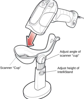
Presentation Mode
The optional Intellistand adds greater flexibility to scanning operation. When you place the digital scanner in the stand’s “cup,” the scanner’s built-in sensor places the scanner in presentation (hands-free) mode. When you remove the digital scanner from the stand it operates in its normal hand-held mode.
Figure 2-2 Scanning in Hands-Free Mode To operate the digital scanner in the Intellistand:
1. Connect the digital scanner to the host (see the appropriate host chapter for information on host connections). 2. Insert the digital scanner in the Intellistand by placing the front of the digital scanner into the stand’s “cup” (see
Figure 2-2).
3. Use the Intellistand’s adjustment knobs to adjust the height and angle of the digital scanner. 4. Center the symbol in the aiming pattern.
5. Upon successful decode, the digital scanner beeps and the LED turns green. For more information on beeper and LED definitions, see Table 2-1 on page 2-2 and Table 2-2 on page 2-4.
NOTE Certain areas of the digital scanner’s handle may feel warm at times. This is normal.
Scanner “Cup” Adjust height of IntelliStand
Adjust angle of scanner “cup”
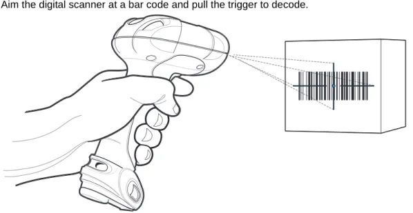
Hand-Held Scanning
DS3508-SR/HD/DP Hand-Held Scanning
Aim the digital scanner at a bar code and pull the trigger to decode.
Figure 2-3 Scanning in Hand-Held Mode - DS3508-SR/HD/DP
Aiming
Imager Aiming
When scanning, the digital scanner projects a red laser aiming pattern which allows positioning the bar code within its field of view. See Decode Ranges on page 2-8 for the proper distance to achieve between the digital scanner and a bar code.
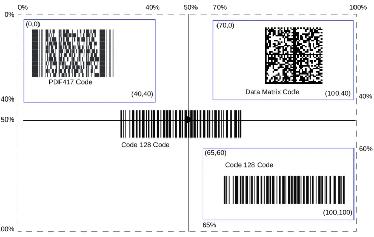
If necessary, the digital scanner turns on its red LEDs to illuminate the target bar code.To scan a bar code, center the symbol in any orientation within the aiming pattern. Be sure the entire symbol is within the rectangular area formed by the cross pattern.
Figure 2-5 Scanning Orientation with Imager Aiming Pattern
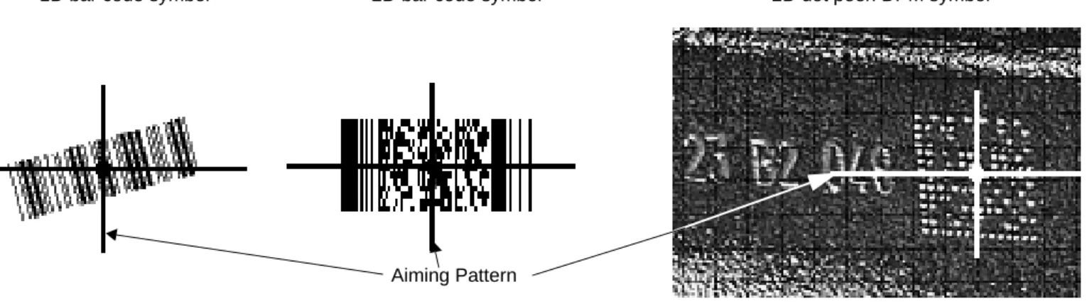
The digital scanner can also read a bar code presented within the aiming pattern but not centered. The top examples in Figure 2-6 show acceptable aiming options, while the bottom examples can not be decoded.
Figure 2-6 Acceptable and Incorrect Aiming
1D bar code symbol 2D bar code symbol 2D dot peen DPM symbol
Aiming Pattern
NOTE Scanning Direct Part Mark (DPM) bar codes with the DS3508-DP20005Rdigital scanner: Due to the reflective nature of some surfaces used with DPM bar codes (see Figure 2-5), it may be necessary to tilt the scanner at an angle relative to the target (Motorola recommends 25-45 degrees). For example, when scanning a 15 mil dot peen Datamatrix bar code marked on an aluminum surface with the
DS3508-DP20005R, present the target between two and three inches from the nose of the scanner, and tilt the scanner at a 30 degree angle.
When scanning standard (non-DPM) bar codes with any configuration of the DS3508 digital scanner, follow the standard aiming instructions described in Aiming on page 2-6.
0 1 234 5
0 1 234 5
0 1 234 5
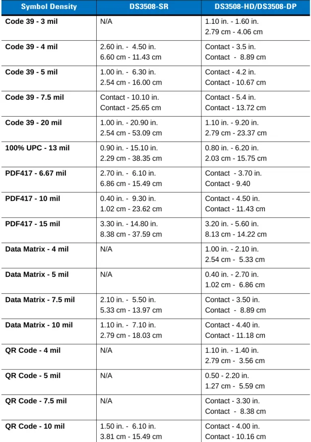
Decode Ranges
Table 2-3 DS3508-SR/HD/DS3508-DP Depth of Field
Symbol Density DS3508-SR DS3508-HD/DS3508-DP
Code 39 - 3 mil N/A 1.10 in. - 1.60 in.
2.79 cm - 4.06 cm
Code 39 - 4 mil 2.60 in. - 4.50 in. 6.60 cm - 11.43 cm
Contact - 3.5 in. Contact - 8.89 cm
Code 39 - 5 mil 1.00 in. - 6.30 in. 2.54 cm - 16.00 cm
Contact - 4.2 in. Contact - 10.67 cm
Code 39 - 7.5 mil Contact - 10.10 in. Contact - 25.65 cm
Contact - 5.4 in. Contact - 13.72 cm
Code 39 - 20 mil 1.00 in. - 20.90 in. 2.54 cm - 53.09 cm
1.10 in. - 9.20 in. 2.79 cm - 23.37 cm
100% UPC - 13 mil 0.90 in. - 15.10 in. 2.29 cm - 38.35 cm
0.80 in. - 6.20 in. 2.03 cm - 15.75 cm
PDF417 - 6.67 mil 2.70 in. - 6.10 in. 6.86 cm - 15.49 cm
Contact - 3.70 in. Contact - 9.40
PDF417 - 10 mil 0.40 in. - 9.30 in. 1.02 cm - 23.62 cm
Contact - 4.50 in. Contact - 11.43 cm
PDF417 - 15 mil 3.30 in. - 14.80 in. 8.38 cm - 37.59 cm
3.20 in. - 5.60 in. 8.13 cm - 14.22 cm
Data Matrix - 4 mil N/A 1.00 in. - 2.10 in. 2.54 cm - 5.33 cm
Data Matrix - 5 mil N/A 0.40 in. - 2.70 in. 1.02 cm - 6.86 cm
Data Matrix - 7.5 mil 2.10 in. - 5.50 in. 5.33 cm - 13.97 cm
Contact - 3.50 in. Contact - 8.89 cm
Data Matrix - 10 mil 1.10 in. - 7.10 in. 2.79 cm - 18.03 cm
Contact - 4.40 in. Contact - 11.18 cm
QR Code - 4 mil N/A 1.10 in. - 1.40 in.
2.79 cm - 3.56 cm
QR Code - 5 mil N/A 0.50 - 2.20 in.
1.27 cm - 5.59 cm
QR Code - 7.5 mil N/A Contact - 3.30 in.
Contact - 8.38 cm
QR Code - 10 mil 1.50 in. - 6.10 in. 3.81 cm - 15.49 cm
Contact - 4.00 in. Contact - 10.16 cm
Specifications
Introduction
This chapter provides suggested digital scanner maintenance, troubleshooting, technical specifications, and signal descriptions (pinouts).
Maintenance
Cleaning the scan window is the only maintenance required. A dirty window can affect scanning accuracy.
•
Do not allow abrasive material to touch the window.•
Remove any dirt particles with a damp cloth.•
Wipe the window using a tissue moistened with ammonia/water.•
Do not spray water or other cleaning liquids directly into the window.Troubleshooting
Table 3-1 Troubleshooting
Problem Possible Causes Possible Solutions
The aiming pattern does not appear when pressing the trigger.
No power to the digital scanner. If the configuration requires a power supply, re-connect the power supply. Incorrect host interface cable is used. Connect the correct host interface
cable.
Interface/power cables are loose. Re-connect cables.
Digital scanner is disabled. For IBM 468x and USB IBM hand-held, IBM table top, and OPOS modes, enable the digital scanner via the host interface. Otherwise, see the technical person in charge of scanning.
If using RS-232 Nixdorf B mode, CTS is not asserted.
Assert CTS line.
Aiming pattern is disabled. Enable the aiming pattern. See Hand-Held Decode Aiming Pattern on page 4-29.
Digital scanner emits short low/short medium/short high beep sequence (power-up beep sequence) more than once.
The USB bus may put the digital scanner in a state where power to the scanner is cycled on and off more than once.
Normal during host reset.
Digital scanner emits aiming pattern, but does not decode the bar code.
Digital scanner is not programmed for the correct bar code type.
Program the digital scanner to read that type of bar code. See Chapter 11, Symbologies.
Bar code symbol is unreadable. Scan test symbols of the same bar code type to determine if the bar code is defaced.
The symbol is not completely inside aiming pattern.
Move the symbol completely within the aiming pattern.
Digital scanner emits 4 short high beeps during decode attempt.
Digital scanner has not completed USB initialization.
Digital scanner decodes bar code, but does not transmit the data to the host.
Digital scanner is not programmed for the correct host type.
Scan the appropriate host type programming bar code. See the chapter corresponding to the host type. Interface cable is loose. Re-connect the cable.
If the digital scanner emits 4 long low beeps, a transmission error occurred.
Set the scanner's communication parameters to match the host's setting. If the digital scanner emits 5 low
beeps, a conversion or format error occurred.
Configure the digital scanner's conversion parameters properly.
If the digital scanner emits low/high/low beeps, it detected an invalid ADF rule.
Program the correct ADF rules. Refer to the Advanced Data Formatting Programmer Guide.
If the digital scanner emits high/low beeps, the scanner is buffering Code 39 data.
Normal scanning a Code 39 bar code and the Code 39 Buffering option is enabled.
Host displays scanned data incorrectly.
Digital scanner is not programmed to work with the host.
Scan the appropriate host type programming bar code.
For RS-232, set the digital scanner's communication parameters to match the host's settings.
For a Keyboard Wedge configuration, program the system for the correct keyboard type, and turn off the CAPS LOCK key.
Program the proper editing options (e.g., UPC-E to UPC-A Conversion). Digital scanner emits
high/high/high/low beeps when not in use.
RS-232 receive error. Normal during host reset. Otherwise, set the digital scanner's RS-232 parity to match the host setting.
Digital scanner emits low/high beeps during programming.
Input error or Cancel bar code was scanned.
Scan the correct numeric bar codes within range for the parameter programmed.
Digital scanner emits
low/high/low/high beeps during programming.
Out of ADF parameter storage space. Erase all rules and re-program with shorter rules.
Table 3-1 Troubleshooting (Continued)
Digital scanner emits low/high/low beeps.
Clearing Code 39 buffer. Normal when scanning the Code 39 Buffering Clear Buffer bar code or upon attempt to transmit an empty Code 39 buffer.
Digital scanner emits a power-up beep after changing USB host type.
The USB bus re-established power to the digital scanner.
Normal when changing USB host type.
Digital scanner emits one high beep when not in use.
In RS-232 mode, a <BEL> character was received and Beep on <BEL> option is enabled.
Normal when Beep on <BEL> is enabled and the digital scanner is in RS-232 mode.
Table 3-1 Troubleshooting (Continued)
Problem Possible Causes Possible Solutions
NOTE If after performing these checks the digital scanner still experiences problems, contact the distributor or call Motorola Enterprise Mobility Support. See page 14 for the telephone numbers.
Technical Specifications
Table 3-2 Technical Specifications
Item Description
Physical Characteristics
Dimensions 7.34 in. H x 4.82 in. W x 2.93 in. D 18.65 cm H x 12.25 cm W x 7.43 cm D Weight (without cable) 11.85 oz. (336 gm)
Voltage and Current 5 volts ±10%, 330mA
Performance Characteristics
Light Source Aiming pattern: 650nm visible laser diode Illumination: 630nm LED
Imager Field of View Standard Range Focus: 39.6 H x 25.7 V High Density Focus: 38.4 H x 24.9 V Roll/Pitch/Yaw ±360, ±60, ±60
Motion Tolerance Programmable up to 100 in./254 cm/sec. when in presentation mode (Horizontal Read Rate)
Symbology Decode Capability
1D UPC/EAN (UPCA/UPCE/UPCE1/EAN-8/EAN-13/ JAN-8/JAN-13 plus
supplementals, ISBN (Bookland), ISSN, Coupon Code), Code 39 (Standard, Full ASCII, Trioptic), Code 128 (Standard, Full ASCII, UCC/EAN-128, ISBT-128 Concatenated), Code 93, Codabar/NW7,Code 11 (Standard, Matrix 2 of 5), MSI Plessey, I 2 of 5 (Interleaved 2 of 5 / ITF, Discrete 2 of 5, IATA, Chinese 2 of 5), GS1 DataBar (Omnidirectional, Truncated, Stacked, Stacked Omnidirectional, Limited, Expanded, Expanded Stacked, Inverse), Base 32 (Italian Pharmacode) PDF417 (and variants) PDF417 (Standard, Macro), MicroPDF417 (Standard, Macro), Composite Codes
(CC-A, CC-B, CC-C)
2D TLC-39, Aztec (Standard, Inverse), MaxiCode, DataMatrix/ECC 200 (Standard, Inverse), QR Code (Standard, Inverse, Micro)
Postal U.S. Postnet and Planet, U.K. Post, Japan Post, Australian Post, Netherlands KIX Code, Royal Mail 4 State Customer, UPU FICS 4 State Postal, USPS 4CB
DPM Marks (DPM unit only) Datamatrix marks applied by dot-peening. All supported barcode types listed above marked by laser etching, chemical etching, ink marking, molding, stamping or casting methods on surfaces such as including metal, plastic, rubber or glass IUID Support Supports IUID parsing. The ability to read and separate IUID
fields per application requirements Nominal Working Range
(Handheld)
Interfaces Supported USB, RS-232, RS-485 (IBM 46xx Protocols), Keyboard Wedge
User Environment
Operating Temperature -4° to 122° F (-20° to 50° C) Storage Temperature -40° to 140° F (-40° to 60° C)
Humidity 5% to 95% relative humidity, non-condensing
Drop Specifications Unit functions normally after repeated 6.5 ft. (2 m) drops to concrete Ambient Light Immunity Incandescent: 150 ft. candles (1,600 LUX)
Sunlight: 8,000 ft. candles (86,000 LUX) Fluorescent: 150 ft. candles (1,600 LUX) Mercury Vapor: 150 ft. candles (1,600 LUX) Sodium Vapor: 150 ft. candles (1,600 LUX)
Immune to direct exposure to normal office and factory lighting conditions, as well as direct exposure to sunlight
Electrostatic Discharge Conforms to 20 kV air discharge and 8 kV of contact discharge Table 3-2 Technical Specifications (Continued)
Digital Scanner Signal Descriptions
Figure 3-1 Digital Scanner Cable Pinouts
Cable interface port
Interface cable modular connector Bottom of scanner
PIN 1 PIN 10
The signal descriptions in Table 3-3 apply to the connector on the digital scanner and are for reference only. Table 3-3 Digital Scanner Signal Pin-outs
Pin IBM RS-232 Keyboard
Wedge USB
1 Reserved Reserved Reserved Jump to Pin 6
2 Power Power Power Power
3 Ground Ground Ground Ground
4 IBM_A(+) TxD KeyClock Reserved
5 Reserved RxD TermData D +
6 IBM_B(-) RTS KeyData Jump to Pin 1
7 Reserved CTS TermClock D
-8 Reserved Reserved Reserved Reserved
9 Reserved Reserved Reserved Reserved
Digital Scanner Options
Introduction
You can program the digital scanner to perform various functions, or activate different features. This chapter describes each user preference feature and provides programming bar codes for selecting these features. The digital scanner ships with the settings shown in Table 4-1 on page 4-2 (also see Appendix A, Standard Default Parameters for all host device and miscellaneous defaults). If the default values suit requirements, programming is not necessary.
To set feature values, scan a single bar code or a short bar code sequence. The settings are stored in non-volatile memory and are preserved even when the digital scanner is powered down.
If not using a USB cable, select a host type (see each host chapter for specific host information) after the power-up beeps sound. This is only necessary upon the first power-up when connected to a new host.
To return all features to default values, scan the Set Default Parameter on page 4-5. Throughout the programming bar code menus, asterisks indicate (
*
)default values.NOTE Most computer monitors allow scanning the bar codes directly on the screen (when using the imaging engine). When scanning from the screen, be sure to set the document magnification to a level where you can see the bar code clearly, and bars and/or spaces are not merging.
*
High Volume (00h)Feature/Option
*
Indicates DefaultScanning Sequence Examples
In most cases, scanning one bar code sets the parameter value. For example, to set the beeper tone to high, scan the High Frequency (beeper tone) bar code listed under Beeper Tone on page 4-10. The digital scanner issues a fast warble beep and the LED turns green, signifying a successful parameter entry.
Other parameters, such as Serial Response Time-Out or Data Transmission Formats, require scanning several bar codes. See these parameter descriptions for this procedure.
Errors While Scanning
Unless otherwise specified, to correct an error during a scanning sequence, just re-scan the correct parameter.
User Preferences/Miscellaneous Options Parameter Defaults
Table 4-1 lists defaults for user preferences parameters. To change the default values, scan the appropriate bar codes in this guide. These new values replace the standard default values in memory. To recall the default parameter values, scan the Set Default Parameter on page 4-5.
NOTE See Appendix A, Standard Default Parameters for all user preferences, hosts, symbologies, and miscellaneous default parameters.
Table 4-1 User Preferences Parameter Defaults
Parameter Parameter
Number Default
Page Number
User Preferences
Set Default Parameter Set Defaults 4-5
Parameter Bar Code Scanning ECh Enable 4-6
Decode Pager Motor F1h 65h Enable 4-7
Decode Pager Motor Duration F1h 72h 500 msec 4-7
Beep After Good Decode 38h Enable 4-9
Beeper Tone 91h Medium 4-10
Beeper Volume 8Ch High 4-9
Beeper Duration F1 74h Medium 4-11
Suppress Power-up Beeps F1h D1h Do Not Suppress 4-11
Hands-Free Mode F1h 76h Enable 4-12
Presentation Performance Mode F1 8Ah Standard 4-12
Time Delay to Presentation Sleep Mode F1 96h 1 Hour 4-16
Low Power Mode 80h Disable 4-18
Time Delay to Low Power Mode 92h 1 Hour 4-19
Trigger Mode 8Ah Standard (Level) 4-21
Fuzzy 1D Processing F1h 02h Enable 4-22
Picklist Mode F0h 92h Disabled Always 4-23
PDF Prioritization F1h CFh Disable 4-24
PDF Prioritization Timeout
F1h D0h
200 ms 4-25DPM Scanning F1h 09h Enable 4-26
Continuous Bar Code Read F1 89h Disable 4-27
Decode Session Timeout 88h 9.9 Sec 4-27
Timeout Between Decodes, Same Symbol 89h 0.5 Sec 4-28
Timeout Between Decodes, Different Symbols 90h 0.2 Sec 4-28
Hand-Held Decode Aiming Pattern F0h 32h Enable 4-29
Hands-Free Decode Aiming Pattern F1h 4Eh Enable for PDF 4-30
Presentation Mode Field of View F1h 61h Full 4-31
LCD Read Mode F1h CCh Disable 4-32
Decoding Illumination F0h, 2Ah Enable 4-33
Multicode Mode F1h, A5h Disable 4-34
Multicode Expression F1h, 95h 1 4-35
Multicode Mode Concatenation F1h, CDh Disable 4-40
Multicode Concatenation Symbology F1h, D2h Concatenate as PDF417 4-41
Miscellaneous Options
Transmit Code ID Character 2Dh None 4-44
Prefix Value 63h, 69h 7013 <CR><LF> 4-45 Suffix 1 Value Suffix 2 Value 62h 68h 64h 6Ah 7013 <CR><LF> 4-45 Table 4-1 User Preferences Parameter Defaults (Continued)
Parameter Parameter
Number Default
Page Number
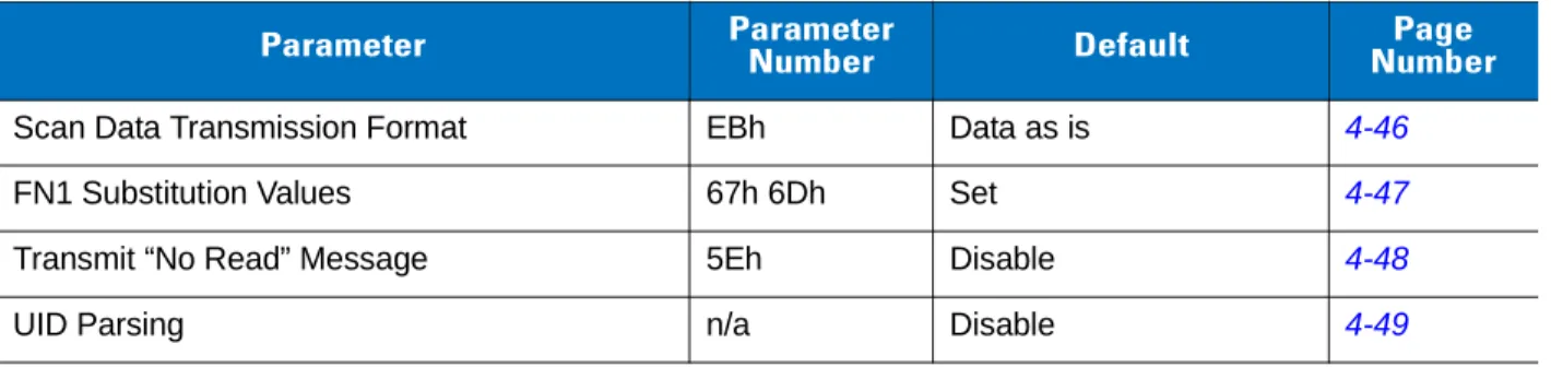
Scan Data Transmission Format EBh Data as is 4-46
FN1 Substitution Values 67h 6Dh Set 4-47
Transmit “No Read” Message 5Eh Disable 4-48
UID Parsing n/a Disable 4-49
Table 4-1 User Preferences Parameter Defaults (Continued)
Parameter Parameter
Number Default
Page Number
User Preferences
Set Default Parameter
You can reset the digital scanner to two types of defaults: factory defaults or custom defaults. Scan the appropriate bar code below to reset the decoder to its default settings and/or set its current settings as custom defaults.
•
Set Defaults - Scan this bar code to reset all default parameters as follows.• If you previously set custom defaults by scanning Write to Custom Defaults, scan Set Defaults to retrieve and restore the decoder’s custom default settings.
• If you did not set custom defaults, scan Restore Defaults to restore the factory default values listed in Table A-1.
•
Set Factory Defaults - Scan this bar code to restore the factory default values listed in Table A-1. This deletes any custom defaults set.•
Write to Custom Defaults - Scan this bar code to set the current decoder settings as custom defaults. Onceset, you can recover custom default settings by scanning Restore Defaults.
*Set Defaults
Set Factory Defaults
Parameter Bar Code Scanning
Parameter # ECh
To disable the decoding of parameter bar codes, including the Set Defaults parameter bar codes, scan the
Disable Parameter Scanning bar code below. To enable decoding of parameter bar codes, scan Enable Parameter Scanning.
*
Enable Parameter Bar Code Scanning (01h)Disable Parameter Bar Code Scanning (00h)
Decode Pager Motor Enable
Parameter # F1h 65h
The scanner includes a pager motor which, when enabled, vibrates the scanner for a period of time when a successful decode occurs.
Scan a bar code below to enable or disable the pager motor. If enabled, scan the appropriate bar code to set the period of time in which to vibrate the scanner (see Decode Pager Motor Duration below).
Decode Pager Motor Duration
Parameter # F1h 72h
NOTE When the pager motor is enabled and the scanner is in IntelliStand, the pager motor disables until the scanner is removed from IntelliStand.
Pager Motor Disable (00h)
*Pager Motor Enable (01h)
150 msec
Decode Pager Motor Enable (continued)
250 msec 300 msec 400 msec *500 msec 600 msec 750 msecBeep After Good Decode
Parameter # 38h
Scan a bar code below to select whether or not the digital scanner beeps after a good decode. If selecting Do Not
Beep After Good Decode, the beeper still operates during parameter menu scanning and to indicate error
conditions.
Beeper Volume
Parameter # 8Ch
To select a beeper volume, scan the Low Volume, Medium Volume, or High Volume bar code.
*
Beep After Good Decode (Enable)(01h)
Do Not Beep After Good Decode (Disable) (00h) Low Volume (02h) Medium Volume (01h)
*
High Volume (00h)Beeper Tone
Parameter # 91h
To select a decode beep frequency (tone), scan one of the following bar codes.
Off (03h) Low Tone (02h)
*
Medium Tone (01h) High Tone (00h)Medium to High Tone (2-tone) (04h)
Beeper Duration
Parameter # F1 74h
To select the duration for the beeper, scan one of the following bar codes.
Suppress Power-up Beeps
Parameter # F1h D1h
Select whether or not to suppress the digital scanner’s power-up beeps. Short (00h)
*
Medium (01h) Long (02h)*
Do Not Suppress Power-up Beeps (00h)Suppress Power-up Beeps (01h)
Hands-Free Mode
Parameter # F1h 76h
In hands-free mode, when you place the digital scanner in the scan stand, it automatically triggers when presented with a bar code. Lifting the digital scanner causes it to behave according to the setting of the Trigger Mode on page 4-21.
If you select Disable Hands-Free Mode, the digital scanner behaves according to the setting of the Trigger Mode regardless of whether it is hand-held or in the scan stand.
Presentation Performance Mode
Parameter # F1 8Ah
Select Standard Presentation Mode when presenting objects to the scanner. Select Enhanced Presentation
Mode when swiping items underneath the scanner.
Digital Scanner Activity Modes
The digital scanner is capable of four modes of activity:
•
Active Mode - The digital scanner uses full illumination for active scanning.*
Enable Hands-Free Mode(01h)
Disable Hands-Free Mode (00h)
*
Standard Presentation Mode (02h)Enhanced Presentation Mode (00h)
•
Idle Mode - In presentation mode only, the digital scanner’s illumination dims after a programmable timeperiod. See Time Delay to Presentation Idle Mode on page 4-14. The digital scanner wakes when it is lifted or senses motion, upon presentation of a bar code, or upon a trigger pull.
•
Sleep Mode - In presentation mode only, the digital scanner’s illumination shuts off after a programmabletime period after Idle Mode has expired. See Time Delay to Presentation Sleep Mode on page 4-16. The digital scanner wakes when it is lifted or senses motion, upon presentation of a bar code (depending on ambient light conditions), or upon a trigger pull.
•
Low Power Mode - The digital scanner enters a low power consumption mode after Sleep Mode hasexpired, in which the LEDs turn off in order to conserve energy and prolong the life of the scanner. See Low Power Mode. In hand-held mode, this occurs immediately after the programmed Time Delay to Low Power Mode. In presentation mode, this occurs after idle mode and sleep mode. The digital scanner wakes when it is lifted, senses a trigger pull, or when the host attempts to communicate.
Figure 4-1 Power Levels
NOTE The digital scanner does not use Low Power Mode when connected to a USB or IBM host.
Active Mode
Idle Mode
Sleep Mode
Low Power Mode
Time Delay to Presentation Idle Mode value
Time Delay to Presentation Sleep Mode value
Time Delay to Low Power Mode value
Time Delay to Presentation Idle Mode
Parameter # F1 97h
In Presentation Mode, this parameter sets the time the digital scanner remains active before entering idle mode with dim illumination. The digital scanner wakes upon presentation of a bar code or a trigger pull.
Disable (00h) 1 Second (01h) 10 Seconds (0Ah) *1 Minute (11h) 5 Minutes (15h) 15 Minutes (1Bh)
Time Delay to Presentation Idle Mode (continued)
30 Minutes (1Dh) 45 Minutes (1Eh) 1 Hour (21h) 3 Hours (23h) 6 Hours (26h) 9 Hours (29h)Time Delay to Presentation Sleep Mode
Parameter # F1 96h
In Presentation Mode, this parameter sets the time the digital scanner remains active before entering sleep mode with no illumination. The digital scanner wakes when it senses motion, upon presentation of a bar code, or a trigger pull.
NOTE Digital scanner performance is not guaranteed in dim conditions.
Disable (00h) 1 Second (01h) 10 Seconds (0Ah) 1 Minute (11h) 5 Minutes (15h)
Time Delay to Presentation Sleep Mode (continued)
15 Minutes (1Bh) 30 Minutes (1Dh) 45 Minutes (1Eh) *1 Hour (21h) 3 Hours (23h) 6 Hours (26h) 9 Hours (29h)Low Power Mode
Parameter # 80h
If enabled, the digital scanner enters a low power consumption mode after Sleep Mode has expired, in which the LEDs turn off in order to conserve energy and prolong the life of the scanner. In hand-held mode, this occurs immediately after the programmed Time Delay to Low Power Mode. In presentation mode, this occurs after idle mode and sleep mode. The digital scanner wakes when it is lifted, senses a trigger pull, or when the host attempts to communicate.
If disabled, power remains on after each decode attempt.
*
Disable Low Power Mode (00h)Enable Low Power Mode (01h)