H
H
H
P
P
P
N
N
N
A
A
A
3
3
3
.
.
.
1
1
1
E
E
E
O
O
O
C
C
C
M
M
M
a
a
a
n
n
n
a
a
a
g
g
g
e
e
e
d
d
d
C
C
C
o
o
o
n
n
n
c
c
c
e
e
e
n
n
n
t
t
t
r
r
r
a
a
a
t
t
t
o
o
o
r
r
r
a
a
a
n
n
n
d
d
d
B
B
B
r
r
r
i
i
i
d
dg
d
g
g
e
e
e
N
Copyright
Copyright © 2011 by National Enhance Technology Corp. All rights reserved. Trademarks
NETSYS is a trademark of National Enhance Technology Corp.
Other brand and product names are registered trademarks or trademarks of their respective holders. Legal Disclaimer
The information given in this document shall in no event be regarded as a guarantee of conditions or characteristics. With respect to any examples or hints given herein, any typical values stated herein and/or any information regarding the application of the device, National Enhance Technology Corp. hereby disclaims any and all warranties and liabilities of any kind, including without limitation warranties of non-infringement of intellectual property rights of any third party.
Statement of Conditions
In the interest of improving internal design, operational function, and/or reliability, NETSYS reserves the right to make changes to the products described in this document without notice. NETSYS does not assume any liability that may occur due to the use or application of the product(s) or circuit layout(s) described herein.
Maximum signal rate derived from IEEE Standard specifications. Actual data throughput will vary. Network conditions and environmental factors, including volume of network traffic, building materials and construction, and network overhead, lower actual data throughput rate. Netsys does not warrant that the hardware will work properly in all environments and applications, and makes no warranty and representation, either implied or expressed, with respect to the quality, performance, merchantability, or fitness for a particular purpose. Make sure you follow in line with the environmental conditions to use this product.
Foreword
Attention:
Be sure to read this manual carefully before using this product. Especially Legal Disclaimer, Statement
of Conditions and Safety Warnings.
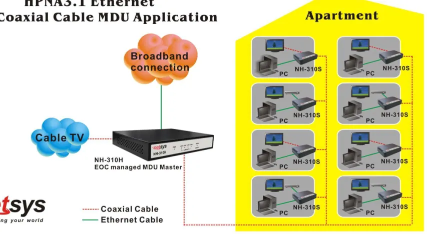
Netsys’ NH-310H and NH-310S are the latest technological innovation of HomePNA3.1 Ethernet over coaxial managed concentrator and bridged (client) respectively. NH-310H EOC managed concentrator is designed to connect with NH-310S MDU bridged for MDU and MTU applications that leverage the two most popular network connections for home use: 10/100Mbps Ethernet connection and coaxial cable connection.
It is a norm that MDU and MTU are equipped with wired network that simply transfer small files and shared applications, but the need for triple play services like transferring large multimedia files such as music, video, photo and deliver high speed VOIP data are ever increasing.
This is why NH-310H/S is designed to be a cost effective MDU and MTU solution. With plug & play, this simply eliminates the pain in modification and high infrastructure cost. With the data transmission up to 200Mbps and link establish under -145dBm/Hz noise floor, it meets the growing demand for high speed multimedia services. Most importantly, with MDU and MTU applications, it allows networking for any locations such as buildings, apartments, hotels, resorts, sports center and other places that need a high bandwidth network.
Caution:
The NH-310H and NH-310S are for indoor applications only. This product does not have waterproof protection, please do not use in outdoor applications.
Safety Warnings
For your safety, be sure to read and follow all warning notices and instructions before using the device.
DO NOT open the device or unit. Opening or removing covers can expose you to dangerous high voltage points or other
risks. ONLY qualified service personnel can service the device. Please contact your vendor for further information.
Use ONLY the dedicated power supply for your device. Connect the power to the right supply voltage (110V AC used for
North America and 230V AC used for Europe, NH-310H/S supports 12 VDC power input).
Place connecting cables carefully so that no one will step on them or stumble over them. DO NOT allow anything to rest on
the power cord and do NOT locate the product where anyone can work on the power cord.
DO NOT install nor use your device during a thunderstorm. There may be a remote risk of electric shock from lightning.
DO NOT expose your device to dampness, dust or corrosive liquids.
DO NOT use this product near water, for example, in a wet basement or near a swimming pool.
Connect ONLY suitable accessories to the device.
Make sure to connect the cables to the correct ports.
DO NOT obstruct the device ventilation slots, as insufficient air flow may harm your device.
DO NOT place items on the device.
DO NOT use the device for outdoor applications directly, and make sure all the connections are indoors or have waterproof
protection place.
Be careful when unplugging the power, because it may produce sparks.
Keep the device and all its parts and accessories out of the reach of children.
Clean the device using a soft and dry cloth rather than liquid or atomizers. Power off the equipment before cleaning it.
Table of Contents
COPYRIGHT ... 1
FOREWORD ... 2
SAFETY WARNINGS ... 3
CHAPTER 1. UNPACKING INFORMATION... 7
1.1 CHECK LIST...7
CHAPTER 2. HARDWARE DESCRIPTION... 8
2.1FRONT PANEL...8
2.2FRONT INDICATORS...9
2.3REAR PANEL...11
CHAPTER 3. INSTALLATION ... 13
3.1HARDWARE INSTALLATION...13
3.2PRE-INSTALLATION REQUIREMENTS...13
3.3GENERAL RULES...14
3.4HCNACONNECTIONS...15
CHAPTER 4. CONFIGURE THE NH-310H VIA WEB BROWSER... 18
4.1LOGIN...18
4.2SELECT THE MENU LEVEL...19
4.3.1 Administrator Setting ...21
4.3.2 System Time Zone ...22
4.3.3 System Time ...23
4.3.4 Firmware Upgrade ...24
4.3.5 Reboot...25
4.3.6 Reset System...26
4.3.7 Version Info ...27
4.3.8 SNMP...28
4.4SELECT ”LAN” ...30
4.4.1 LAN Settings ...31
4.4.2 LAN Switch Port Setting ...32
4.4.3 LAN Port Status ...33
4.5SELECT ”ROUTE”...34
4.5.1Static Routing...35
4.5.2 Routing Table List ...37
4.6SELECT ”HPNA” ...38
4.6.1 Device Info./Test ...39
4.6.1.1 Concentrator Read Packet Counter ...41
4.6.1.2 End Point Net Interface Test...42
4.6.1.3 End Point Read Packet Counter ...44
4.6.2 Device Control...45
4.6.2.1 EOC driver Upgrade for Concentrator...47
4.6.2.2 HPNA driver Upgrade and user speed control for Bridges ...49
4.6.2.4 Add User for Bridges ...53
4.6.3 User List ...57
CHAPTER 5. CONFIGURE THE NH-310H VIA CONSOLE... 60
5.1SETUP ON HYPERTERMINAL...60
5.2RESET THE SYSTEM TO DEFAULT CONFIGURATION...60
5.3TFTPPROTOCOL FOR FIRMWARE UPGRADE...61
APPENDIX A: CABLE REQUIREMENTS ... 66
APPENDIX B: PRODUCT SPECIFICATION... 69
APPENDIX C: TROUBLESHOOTING ... 72
APPENDIX D: COMPLIANCE AND SAFETY INFORMATION... 78
APPENDIX E: HOME NETWORKING INSTALLATION GUIDE ... 81
APPENDIX F: MDU INSTALLATION GUIDE ... 91
WARRANTY ... 101
Chapter 1.
Unpacking Information
1.1 Check List
Thank you for choosing Netsys NH-310H/S. Before installing the router, please verify the contents inside the package.
Package Contents:
NH-310H or NH-310S Device
4 x rubber foot (NH-310H pre-installed on the bottom, and you can find the rubber foot inside the inner box right
side of the NH-310S)
1 x AC to DC
12V
Power Adapter1 x RJ-45 Cable
Notes:
1. Please inform your dealer immediately for any missing or damaged parts. If possible, retain the carton including the original packing materials. Use them to repack the unit in case there is a need to return for repair.
2. If the product has any issue, please contact your local vendor.
3. Do not use sub-standard power supply. Before connecting the power supply to the device, be sure to check compliance with the specifications. The NH-310H/S supports 12 VDC power input.
4. The power supply included in the package is commercial-grade. Do not use in industrial-grade applications. 5. Please look for the QR code on the bottom of the product, the user can launch the QR code scanning program to scan and download the user’s manual electronic format file.
Chapter 2.
Hardware Description
This chapter describes the important parts of the device. It features the front indicators and rear connectors.
NH-310H Outward
NH-310S Outward
2.1 Front Panel
The front panel provides a simple interface monitoring of the concentrator/bridged. (Figure 2.1)
2.2 Front Indicators
The NH-310H has Six LED indicators. The following Table shows the description. (Table 2-1) Table 2-1 LED Indicators Description and Operation
LEDs
Color
Status
Descriptions
On The HCNA is receiving the power and also functioning properly
Power Green
Off The HCNA is not ready or has malfunctioned
On The LAN port is connected to Ethernet devices
Blinking The HCNA is transferring data LAN1
(Ethernet LED) Green
Off The LAN port is not connected to any Ethernet devices
On The LAN port is connected to Ethernet devices
Blinking The HCNA is transferring data LAN2
(Ethernet LED) Green
Off The LAN port is not connected to any Ethernet devices
On The LAN port is connected to Ethernet devices
Blinking The HCNA is transferring data LAN3
(Ethernet LED) Green
Off The LAN port is not connected to any Ethernet devices
On The LAN port is connected to Ethernet devices
Blinking The HCNA is transferring data LAN4
(Ethernet LED) Green
Off The LAN port is not connected to any Ethernet devices
On The HCNA is link to another HCNA end point device
HCNA
(HCNA LED) Green Blinking The HCNA is active and it is transferring data
Table 2-2 LED Indicators Description and Operation
LEDs Color Status Descriptions
On The HCNA is receiving the power and also functioning properly
Power Green
Off The HCNA is not ready or has malfunctioned
On The LAN port is connected to Ethernet devices
Blinking The HCNA is transferring data LAN1
(Ethernet LED) Green
Off The LAN port is not connected to any Ethernet devices
On The LAN port is connected to Ethernet devices
Blinking The HCNA is transferring data LAN2
(Ethernet LED) Green
Off The LAN port is not connected to any Ethernet devices
On The HCNA is link to another HCNA device
Blinking The HCNA is active and it is transferring data HCNA
(HCNA LED) Green
Off The HCNA is not connected
Green On Actual HCNA link speed is ≧ 128MB
Green Yellow On Actual HCNA link speed is ≧ 64MB and < 128MB
Link Quality (HCNA LED)
2.3 Rear Panel
The rear panel provides the physical connectors connected to the power adapter and any other network device. (Figure 2.2)
Figure 2.2 Rear panel of the NH-310H
And the table shows the description. (Table 2-3)
Table 2-3 Connectors shown on the rear side of the device
Connectors Type Description
HCNA F-type female
coaxial cable
For connecting HCNA port to another HCNA port with RG59 75ohm coaxial cable.(HCNA port spectrum 12M - 44MHz)
TV F-type female
coaxial cable For connecting to TV or STB.(TV port spectrum 47M - 1GHz) LAN1/LAN2/
LAN3/LAN4 RJ-45 For connecting to an Ethernet equipped device
The following figure shows the rear side of the NH-310S. (Figure 2.3) And the table shows the description. (Table 2-4)
Figure 2.3 Rear panel of the NH-310S
Table 2-4 Connectors shown on the rear side of the device
Connectors Type Description
HCNA F-type female
coaxial cable
For connecting HCNA port to another HCNA port with RG59 75ohm cable. (HCNA port spectrum 12M - 44MHz)
TV F-type female
coaxial cable For connecting to TV or STB. (TV port spectrum 47M - 1GHz)
LAN1/LAN2 RJ-45 For connecting to an Ethernet equipped device
Power Power Jack For connecting to 12V/1A power adapter, regarding the NH-310S power
Chapter 3.
Installation
3.1 Hardware Installation
This chapter describes how to install the device and establish the network connections. The NH-310H/S may be installed on any level surface (e.g. a table or shelf). However, please take note of the following minimum site requirements before you begin. NH-310S must be stick the 4 rubber feet at the bottom and the NH-310H pre-installed 4 rubber feet.
3.2 Pre-installation Requirements
Before you start the actual hardware installation, make sure you can provide the right operating environment, including power requirements, sufficient physical space, and proximity to other network devices that are to be connected. Verify the following installation requirement:
• Power requirements: 12VDC (1A or above)
• The device should be located in a cool dry place, with at least 10cm/4in of space at the front and back for ventilation.
• Place the device away from direct sunlight, heat sources, or areas with a high amount of electromagnetic interference.
• If youtrying to setup basic connection between NH-310H and NH-310S, you need to add at least -10dB attenuator (5M-850MHz).
• Check if the network cables and connectors needed for installation are available.
3.3 General Rules
Before making any connections to the device, take note the following rules: • Ethernet Port (RJ-45)
All network connections to the concentrator Ethernet ports must be made using Category 5 UTP or above for 100 Mbps, Category 3, 4 UTP for 10Mbps.
No more than 100 meters of cabling maybe use between the MUX or HUB and an end node.
• HCNA Port (Coaxial)
All Home network connections we recommend use RG59 75ohm coaxial cable and link establish under -145dBm/Hz noise floor.
• Diplexer / Multi-Splitter
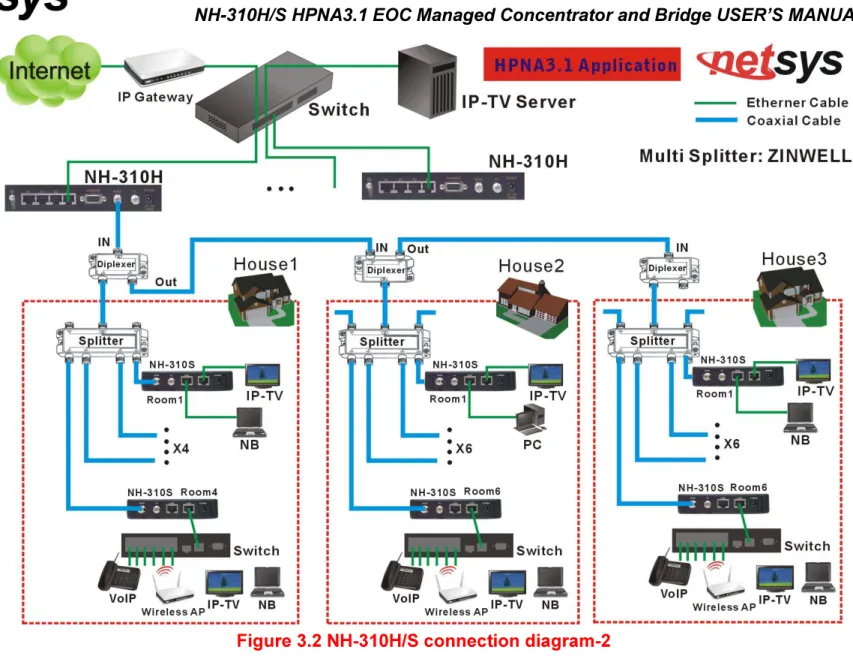
All Home network connections could be use Diplexer or Multi-Splitter or use mix of them as you would like to connect an end point device.Please choose according to different environments to different specifications of the Diplexer (5M-45MHz, 47M-1GHz) or Multi-Splitter (5M-1Ghz).
• Attenuator
Establish the basic link for NH-310H and NH-310S, please add a attenuator (at least -10 dB 5M-850MHz).
3.4 HCNA Connections
The device has been designed to operate on the coaxial cable installed in homes throughout the world. They utilized the same cable and connectors commonly used for television.
The 2x Coaxial connector are used to connect to TV or coaxial wall socket to another device that connect its RJ-45 to the LAN card of another set of PC, notebook, or other internet access device or coaxial connector to TV or set top box. The device’s coaxial connector must support the transmission of data up to 200Mbps across the existing coaxial cable and link establish under -145dBm/Hz noise floor. But make sure that the connector is inserted properly and lock. Ethernet cable used must conform to FCC standard to ensure data integrity and it should not exceed 100meters (328feet).
The NH-310H EOC (Ethernet over coaxial) managed MDU concentrator can support up to 60(maximum) NH-310S Bridges (Clients).
Notes:
1. Please refer to Appendix E: installation guide. There is introduced how to install HPNA3.1 device. 2. Each of the NH-310S can only be connected to 16 nodes (Mac Address).
Chapter 4.
Configure the NH-310H Via Web Browser
The NH-310H provides a built-in HTML based management interface that allows configuration of the NH-310H via Internet Browser. Best viewed using Chrome or Firefox browsers.
In order to use the web browser configure the device, you may need to allow:
• Web browser pop-up windows from your device. Web pop-up blocking is enabled by default in windows XP SP2 or above.
• Java Scripts. (Enabled by default) • Java permissions. (Enabled by default)
Launch your web browser and input the default IP address “192.168.16.249” in the Web page. Following section user can find default password.
4.1 Login
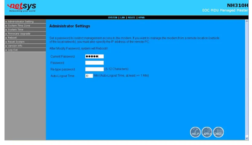
The default login password is “admin“. The password is changeable in Administrator Settings.
4.2 Select the Menu Level
There is an easy Setup for end users at the setup of NH-310H with SYSTEM, LAN, ROUTE, HPNA for more detail configurations.
4.3 Select “SYSTEM”
Select the “SYSTEM”. The menu below will be used frequently. It includes the sub-menus of Administrator Setting、System Time Zone、System Time、SNMP、Firmware Upgrade、Reboot、Reset System、Version Info and Log Out. A screen is displayed as shown in Figure 4.3
4.3.1 Administrator Setting
To add a user or change user’s password, click on the “Administrator Settings” link in the left navigation bar. A screen is displayed as shown in Figure 4.3.1.
4.3.2 System Time Zone
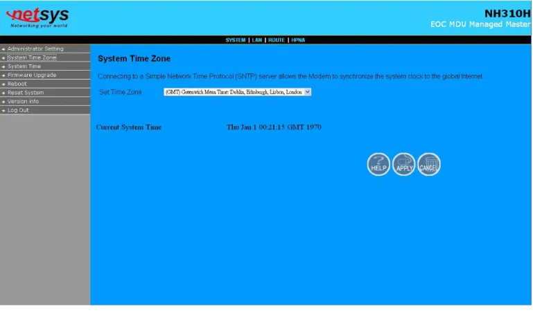
User can set Time Zone by connecting to a Simple Network Time Protocol (SNTP) server allows the Device to synchronize the system clock to the global Internet. The synchronized clock in the Device is used to record the security log and control client filtering. A screen is displayed as shown in Figure 4.3.2.
Figure 4.3.2 System Time Configuration
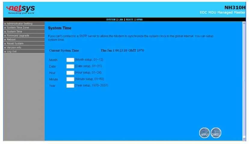
4.3.3 System Time
If user can't connect to a SNTP server to allows the Device to synchronize the system clock to the global Internet. User can
setup “System Time”. A screen is displayed as shown in Figure 4.3.3.
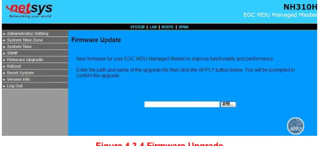
4.3.4 Firmware Upgrade
To update the system firmware, click on the “Firmware Upgrade” link in the left navigation bar. A screen is displayed as shown in Figure 4.3.4
Figure 4.3.4 Firmware Upgrade
The screen contains the following detail:
• Click "Browse" to select a specific file name in preparation upgrade the firmware. • Click “APPLY” to start the firmware update.
Notes:
1. If the machine firmware version is too old, after the firmware upgrade, user must reset system to default that to avoid the new features can not use or system error occurred.
4.3.5 Reboot
To reboot the unit, click on the “Reboot” link in the left navigation bar. A screen is displayed as shown in Figure 4.3.5.
Figure 4.3.5 Reboot NH-310H
• Click “Reboot” to restart the unit.
4.3.6 Reset System
To reset the system, click on the Reset link in the left navigation bar. A screen is displayed as shown in Figure 4.3.6.
Figure 4.3.6 Reset NH-310H
• Click Reset to restart the system to default configuration. • After upgrade the firmware, and then automatically reboot.
• All settings will be cleard, and return to the default IP(192.168.16.249).
Note:
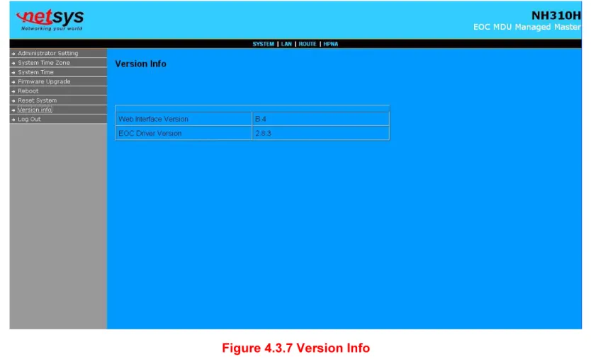
4.3.7 Version Info
This function shows the version of Web Interface firmware and EOC Driver. A screen is displayed as shown in Figure 4.3.7.
Figure 4.3.7 Version Info Note:
4.3.8 SNMP
Any Network Management running the simple Network Management Protocol (SNMP) can manage the switch, provided the Management Information Base (MIB) is installed correctly on the management station. The SNMP is a Protocol that governs the transfer of information between management and agent. A screen is displayed as shown in
Figure 4.3.8.
1. Use this page to define management stations as trap managers and to enter SNMP community strings. User can also define a name, location, and contact person for the switch. Fill in the system options data, and then click Apply to update the changes on this page.
Name: Enter a name to be used for the switch. Location: Enter the location of the switch.
Contact: Enter the name of a person or organization.
2. Community strings serve as passwords and can be entered as one of the following:
RO: Read only. Enables requests accompanied by this string to display MIB-object information.
RW: Read write. Enables requests accompanied by this string to display MIB-object information and to set MIB objects. 3. Trap Manager
A trap manager is a management station that receives traps, the system alerts generated by the switch. If no trap manager
is defined, no traps are issued. Create a trap manager by entering the IP address of the station and a community string.
Trap Host IP: Create a trap manager by entering the IP address. Trap Port: Specifies the trap port. Default trap port is “162”.
Trap community: Create a trap manager by entering a community string. i.e. public.
Note:
4.4 Select ”LAN”
Select “LAN”. The menu below includes the sub-menus of LAN Settings, LAN Switch Port Setting , and LAN Port Status. A screen is displayed as shown in Figure 4.4.
4.4.1 LAN Settings
The form below is used to change the IP address of the LAN (Local Area Network) port “adm0” in the NH-310H and the “adm0” IP address is the CPU IP address of NH-310H for PC to remote control the NH-310H with network management. The proposed IP address is either the default address of adm0 (i.e. 192.168.16.249) or it is the address changed by an ifconfig command via the shell running in the terminal. The Default value of Subnet Mask display is 255.255.255.0. A screen is
displayed as shown in Figure 4.4.1.
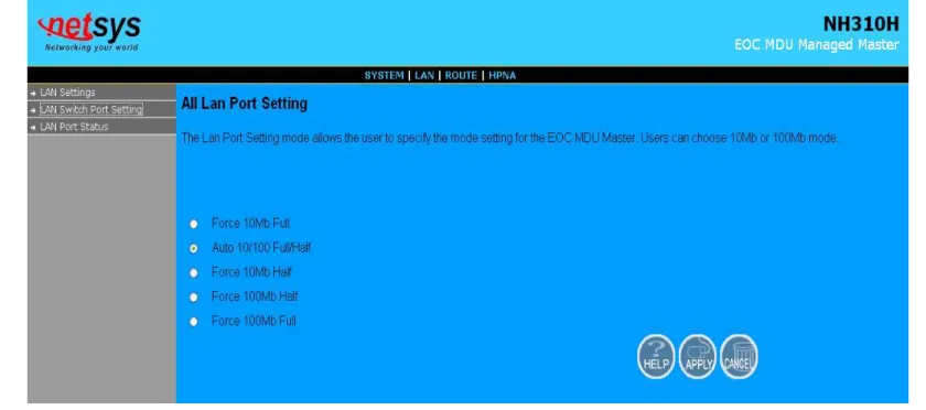
4.4.2 LAN Switch Port Setting
The LAN Port Setting mode allows the user to specify the mode setting for the NH-310H. Users can choose 10Mb or 100 Mb modes for cases as “Force 10Mb Full”, ”Auto 10/100 Full/Half”, ”Force 10Mb Half”, ”Force 100Mb Half”, and “Force 100Mb Full”. The default value is ”Auto 10/100 Full/Half”. A screen is displayed as shown in Figure 4.4.2.
4.4.3 LAN Port Status
The following information provides a view of the current Ethernet ports status of the unit as below:
Figure 4.4.3 LAN Port Status
For this example, the NH-310H EOC MDU managed Concentrator is connected to two NH-310S Bridges with
Port 3 and Port 4.It appears Port3 Link Status Link Up, 100Mb/s, Full Duplex、Port4 Link Status Link Up, 100Mb/s, Full Duplex、 Port1 Link Status Link Down, and Port2 Link Status Link Down. A screen is displayed as shown in Figure 4.4.3.
Example Table:
Input 1 Output 1 Input 2 Output 2 Input 3 Output 3 Input 4 Output 4
NWAY 10M Full 10M Full Force 10M Full 10M Full None Link Down NWAY 10M Half 10M Half
Input 5 Output 5 Input 6 Output 6 Input 7 Output 7 Input 8 Output 8
4.5 Select ”ROUTE”
Select the “ROUTE”. The menu below includes the sub-menus of Static Routing, and Routing Table List. A screen is displayed as shown in Figure 4.5.
4.5.1 Static Routing
To setup Static Routing, click on the “Static Routing” link in the left navigation bar. A screen is displayed as shown in
Figure 4.5.1.
Figure 4.5.1 Static Routing
The screen contains the following details: Fields in Static Routing
Field Description
Destination LAN IP Enter the IP Address 0-0-0-0 of routing entry. Subnet Mask Enter the Subnet Mask 0-0-0-0 of routing entry.
Gateway Enter the Gateway address of routing entry.
Notes:
1. Static Routing functionality is used to define the connected Gateway between the LAN and WAN. For example, if user would like to activate the Network Time Protocol (NTP) service, user have to define the Gateway connected to NTP server in the WAN.
2. The gateway IP domain should be the same LAN, e.g. if the LAN IP is 192.168.1.1, the gateway IP should be 192.168.1.X. (where X represents a number, range is 2-255)
4.5.2 Routing Table List
To view the Routing entry table list of NH-310H , click on the “Routing Table” link in the left navigation bar. A screen is displayed as shown in Figure 4.5.2.
Figure 4.5.2 Routing Table List The screen contains the following details:
4.6 Select ”HPNA”
Select the “HPNA”. The menu below includes the sub-menus of Device Info./Test、Device Control, and User List. A screen is displayed as shown in Figure 4.6.
Figure 4.6 Select ”HPNA” in the Entry Screen Note:
The “HPNA” can configure and manage NH-310H (Concentrator) and NH-310S (Bridge) HPNA functions, please refer to the Function Introduction as below.
4.6.1 Device Info./Test
This sub-menu for Device Info./Test appears the HPNA Device Information of the Numbers、Mode(Concentrator/bridge), MAC Address, Firmware Version , Spectrum for the Concentrator/bridge. It also includes Counter test for Concentrator and
Net_Test, and Counter test for Bridges. A screen is displayed as shown in Figure 4.6.1.
The screen contains the following details:
Mode Test Descriptions
ConcentratorCount Concentrator Read Packet Counter.
User List End Point User List Table No.Refer to section 4.6.1.1
Net_Test End Point Net Interface Test. Refer to section 4.6.1.2
bridge
Count End Point Read Packet Counter.Refer to section 4.6.1.3
Note:
1. Version 2.8.4: EoC driver version, please refer to section 4.6.2(Device Control).
2. Spectrum: HPNA band mode, there are three modes, namely, Full Band(12-44MHz), High Band(28-44Mhz), Low Band(12-28MHz). Please refer to section 4.6.2.1(EOC driver Upgrade for Concentrator).
4.6.1.1 Concentrator Read Packet Counter
Click on “Count” button in the end of line for Concentrator and it appears the window which shows the MAC Address of the Concentrator. A screen is displayed as shown in Figure 4.6.1.1and Figure 4.6.1.2.
Figure 4.6.1.1.1 Concentrator Read Packet Counter
Click on the “Start” button, and the example for test result of Concentrator Read Packet Counter will be as below:
4.6.1.2 End Point Net Interface Test
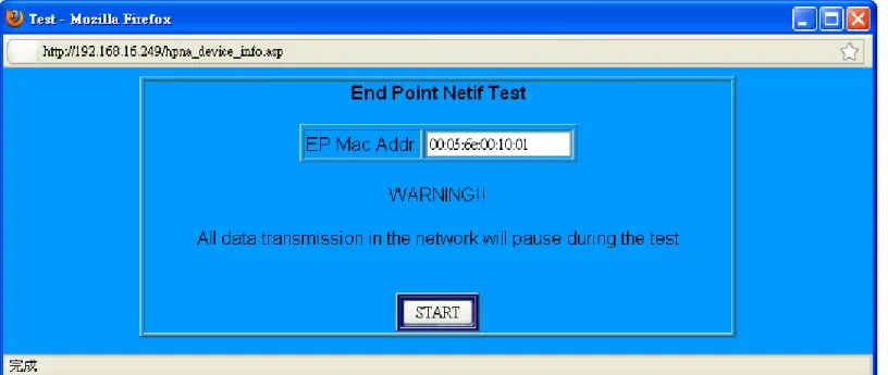
Click on “Net_Test “ button in the line for each bridge and it appears the window which shows the MAC Address of the bridge. A screen is displayed as shown in Figure 4.6.1.2.1. In the pop-up window shows “WARNING!! All data transmission in the network will pause during the test”.
Click on the “START” button, wait for some time you will see the Concentrator Read Packet Counter test results such as the example of Figure 4.6.1.2.2 below:
Figure 4.6.1.2.2 Output of End Point Net Interface Test
It shows the network information regarding the network test results for the SNR, the speed(rate), the receive power, transmitted packets, and the PER.
4.6.1.3 End Point Read Packet Counter
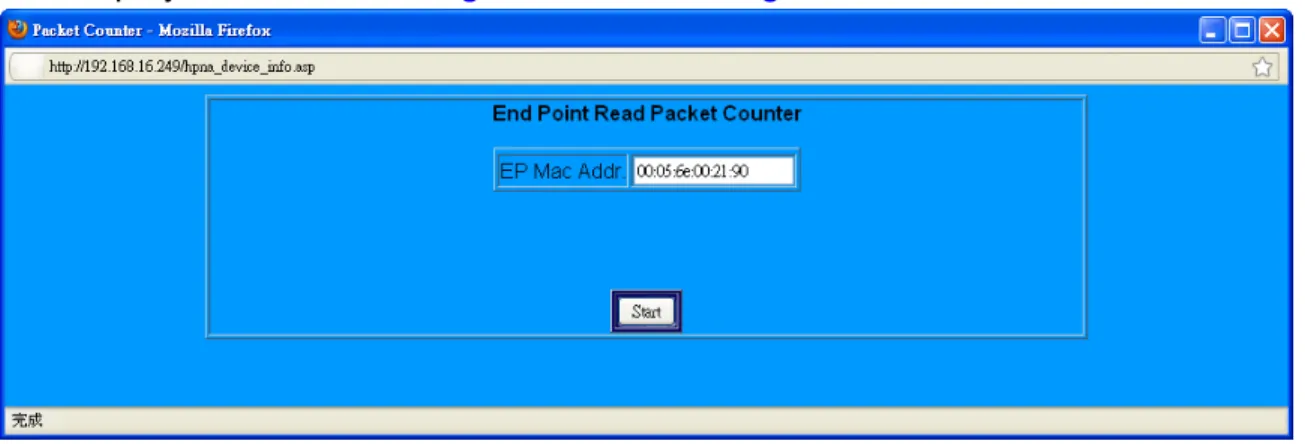
Click on “Count “ button in the line for each bridge and it appears the window which shows the MAC Address of the bridge.
A screen is displayed as shown in Figure 4.6.1.3.1.
Figure 4.6.1.3.1 End Point Read Packet Counter
Click on the “Start” button, and the example for test result of End Point Read Packet Counter will be as below:
4.6.2 Device Control
Select “Device Control”. The menu below includes the sub-menus of Numbers, Mode, MAC Address, and Spectrum for the Concentrator/bridge. The table also includes User List, Firmware driver Upgrade, Reboot and User Add for Bridges. A screen is displayed as shown in Figure 4.6.2.
The screen contains the following details:
Mode Function Descriptions
Concentrator Upgrade EOC driver Upgrade for Concentrator
User List End Point User List Table No
Speed EOC driver Upgrade for Bridges
Reboot Reboot for Bridges
bridge
Add Add User for Bridges
Notes:
1. EoC driver and web firmware is different, due to the Web firmware is control web UI management, the EoC driver is control NH-310H and NH-310S HPNA function. Please see the current driver version is “2.8.4”, such as the Figure 4.6.2.
2. EoC driver contains the web firmware. If user would like to upgrade latest EoC driver, please refer to point 3 and section 4.6.2.2)
3. The first, user need to upgrade latest web firmware, and user need to access Device Control menu, and then click the “Upgrade” from the Firmware table to upgrade EoC driver. A screen is displayed as shown inFigure 4.6.2.
4.6.2.1 EOC driver Upgrade for Concentrator
Click on “Upgrade” button in the line for Concentrator and it appears the window which shows the MAC Address, the New Version and Band Mode of the firmware which contains the EOC Concentrator driver for upgrading.
To Band Mode, it supports Full Band (12-44MHz), High Band (28-44MHz), Low Band (12-28MHz). User can selected band mode to configure HPNA operating band frequency. The pop window also shows the Firmware New Version (i.e. 2.8.4).
Note:
1. If user changed Band Mode, Concentrator and all End Points will auto change the same operating band frequency. 2. The band mode will used in the different environments and different applications. For example, if your equipment noise
signal (i.e. 20MHz) conflict to the EOC working frequency, you have to change EOC band from full band to High Band for preventing the EOC signal overlap the video noise.
Click on the “Start” button, and it only takes short time to upgrade the driver. A screen is displayed as shown in Figure 4.6.2.1.2.
4.6.2.2 HPNA driver Upgrade and user speed control for Bridges
Click on “Upgrade“ button in the line for each bridge and it appears the window which shows the MAC Address and
Enable/Disable Mode of the bridge. It supports Enable or Disable for EOC End Point and also include driver upgrade. The window also shows the Firmware New Version( i.e. 2.8.4). A screen is displayed as shown in Figure 4.6.2.1.1.
Click on the “Start” button with the default Enable Mode and it only takes short time to upgrade the driver.
4.6.2.3 Reboot for Bridges
Click on the “Reboot“ button in the line for each one bridge and it appears the window which shows the MAC Address. A screen is displayed as shown in Figure 4.6.2.3.1.
Click on the “Start” button, and it only takes short time to reboot for each one Bridge.
4.6.2.4 Add User for Bridges
Click the “Add“ button in the line for each bridge and it appears the window which shows the MAC Address and Number/Remark fields. The Remark field is convenient to apply for the User List information such as address and hotel room number…etc.
The Maximum numbers of characters is sixty. A screen is displayed as shown in Figure 4.6.2.4.1. Note:
To the Number field, if you would like to modify the new number of the bridge has been configured, it will replace the older information.
For example, A screen is displayed as shown in Figure 4.6.2.4.2 : (1) Fill No. as 1 (NO.1~ NO.60).
(2) Remark: 9F, NO.208, TATUNG RD, SEC3,HSI CHIH, TAIPEI. (Max characters:60) (3) E1 Vlan ID:0 (0:No VLAN, 2-4095: Tag VLAN)
(4) E2 Vlan ID:0 (0:No VLAN, 2-4095: Tag VLAN) (5) IGMP: OFF (OFF/ON)
(6) Rate Control UP:1M (12 Speed Modes) (7) Rate Control Down:10M (12 Speed Modes) (8) QoS: OFF (OFF/ON)
(9) Click on “Start”. Note:
1. The No. is 1~ 60.
2. Remark can type 60 characters.
3. The VLAN ID is 0 or 2-4095. In HPNA MDU structure, all of the End Points will be isolated. Therefore, if you don't need use 802.1Q Tag VLAN, set VLAN ID=0. When you need IEEE 802.1Q VLAN Tagging application, configure VLAN Id during 2~4095.
4. The Upstream Rate Control have 12 Speed Modes as Full Speed/ 512k/ 1M/ 2M/ 3M/ 4M/ 6M/ 8M/ 10M/ 16M/ 20M/ 30M for EOC End Point.
5. The Downstream Rate Control have 12 Speed Modes as Full Speed/ 512k/ 1M/ 2M/ 3M/ 4M/ 6M/ 8M/ 10M/ 16M/ 20M/ 30M for EOC End Point.
6.The QoS priority packet ratio is 8 : 4 : 2 : 1(Highest : High : Low : Lowest). 7. The above configuration settings take effect immediately after.
8. In order to comply with the MDU / MTU application, NH-310H/S is characterized by a bridged and can pass through any packets. In addition to, the security considerations, each of the NH-310S is independent.
9. Regarding rate control function, which must rely on flow control to limit bandwidth. If client side device doesn't support flow control, the upstream bandwidth control will invalid, so for this case, client side device must support flow control function.
The User Add is done.
Figure 4.6.2.4.3 Example for adding new user for one Bridge
NH-310S tag vlan(web ui) examples:
1. ISP ethernet switch VLAN ID 3→NH-310H→ NH-310S VLAN ID 3→ Access
2. ISP ethernet switch VLAN ID 3→NH-310H→ NH-310S VLAN ID 4→ Reject access 3. 1 x NH-310S VLAN ID 3→NH-310H→ another NH-310S VLAN ID 3→ Reject access
4. A NH-310S VLAN ID 3 of Ethernet port 1 → NH-310S VLAN ID 4 of Ethernet port 2 → Both reject access 5. A NH-310S VLAN ID 3 of Ethernet port 1 → NH-310S VLAN ID 3 of Ethernet port 2 → Access
4.6.3 User List
Follow the example in 4.6.2.4 add a bridge, there are several information appears in User Information window. User can click the “Edit” button to modify each bridge or click the “Erase” button to delete each the bridge information. A screen is displayed as shown in Figure 4.6.3.1.
Figure 4.6.3.1 Erase the No. and click “Start”
Figure 4.6.3.3 Edit User Config of End Point Notes:
1. If user needs to change the settings in the User Information, please click on the “Edit” to change the configuration.
2. Change the settings, user need click on the “User list” button to refresh the User Information. Please refer to Figure 4.6.1.
3. If need, user can disable or enable IGMP and QoS function. 4. IGMP support v1/v2.
Chapter 5.
Configure the NH-310H via Console
5.1 Setup on HyperTerminal
Open the HyperTerminal and set the baud rate to 115200, 8N1N to properly set the HyperTerminal.
A screen is displayed as shown in Figure 5.1.
Figure 5.1 HyperTerminal Configuration
5.2 Reset the system to default configuration
At the CLI command, type the command “rawaccess –e” to reset the system to default configuration. After the commencement of the previous command, then type "reboot" command to restart the system.
5.3 TFTP Protocol for firmware upgrade
(1) Powered on and execute HyperTerminal, within three seconds press the <space>to enter Loader menu. You will see the boot Loader menu with the items of function selection. A screen is displayed as shown in Figure 5.3.1.
(2) Execute the TFTP tool and specify current directory which is stored the NH-310H firmware. Enter the IP address of the TFTP
server interface field.Now the TFTP server is ready for firmware upgrading. A screen is displayed as shown in Figure 5.3.2. Note:
We must remind you must set TFTP tool, do not miss this step!
Figure 5.3.2 TFTP tool for f/w upgrading
(3) Please enter the number: “2” as set TFTP Client Download. A screen is displayed as shown in Figure 5.3.3.
(4)Please enter your option: “s” as set parameters, then enter TFTP Server IP and Remote File Name as the NH-310H firmware for upgrading. A screen is displayed as shown in Figure 5.3.4.
(5) Enter your option: “D” and it will be beginning the TFTP download. After Erasing and Programming flash process, and NH-310H new firmware upgrade is completed. A screen is displayed as shown in Figure 5.3.5.
Appendix A:
Cable Requirements
A CAT 3, 4 or 5 UTP (unshielded twisted pair) cable is typically used to connect the Ethernet device to the device. A
10Base-T cable often consists of four pairs of wires, two of which are used for transmission. The connector at the end of the 10Base-T cable is referred to as an RJ-45 connector and it consists of eight pins. The Ethernet standard uses pins 1, 2, 3 and 6 for data transmission purposes. (Table A-1)
Table A-1 RJ-45 Ethernet Connector Pin Assignments
MDI MDI-X
PIN #
Signal Media Dependant
interface Signal
Media Dependant interface-cross
1 TX+ Transmit Data + RX+ Receive Data +
2 TX- Transmit Data - RX- Receive Data -
3 RX+ Receive Data + TX+ Transmit Data +
4 -- Unused -- Unused
5 -- Unused -- Unused
6 RX- Receive Data - TX- Transmit Data -
7 -- Unused -- Unused
8 -- Unused -- Unused
Figure A-1 Standard RJ-45 repectacle/connector
Note:
Please make sure your connected cables are with same pin assignment as the table above before deploying the cables into your network.
Figure A-2 Pin Assignments and Wiring for an RJ-45 Straight-Through Cable
Serial Console Interface Connector Pin Assignments
The serial console interface connector is a 9-pin, RS-232 D-type, DTE connector. A null device cable is required to connect a workstation running the Linux or Windows operating system. Table A-2 lists the pin assignments for the serial console interface connector.
Table A-2 RS-232 Connector Pin Assignments Description Pin I/O Signal Name
Not used 1 - -
Receive data; input 2 In RXD Transmit data; output 3 Out TXD Data terminal ready; output 4 Out DTR Interface signal ground 5 - GND Data set ready; input 6 In DSR
Not used 7 - -
Not used 8 - -
Not used 9 - -
The device have one standard serial port connector located on the back of the device. Figure A-3 shows the pin number assignments for the 9-pin, male D-shell serial port connector on the back of the device. These pin number assignments conform to the industry standard for RS-232 communications.
Figure A-3
Appendix B:
Product Specification
Key Features & Benefits
• Compliant with HomePNA3.1/ HomePNA3.0 over Coaxial cable(HCNA) specifications (ITU-T G.9954) • Compliant with IEEE802.3 10Base-T and IEEE802.3u 100Base-Tx standards
• Compliant with IEEE802.3x Flow Control standard
• Provide 4 x 10/100M auto-negotiation RJ-45 Ethernet ports with auto-MDI/MDIX(NH-310H only) • Provide 2 x 10/100M auto-negotiation RJ-45 Ethernet ports with auto-MDI/MDIX(NH-310S only) • Provides 2 x F-type female coax connectors for HCNA(12M-44MHz) and TV(47M-1GHz)
• Support transmission speed up to 200Mbps over coaxial cable and link establish under -145dBm/Hz Noise Floor • Support point to multipoint application
• Support HPNA Master/Endpoints driver upgrade
• Support IEEE802.1p Priority Mapping and IEEE802.1p/TOS Priority Queue
• Support IEEE802.1Q Tag VLAN Pass Through
• Support Web Management(HTTP),Telnet for Remote Management (NH-310H only)
• Support HTTP and TFTP protocol for firmware upgrade(NH-310H only)
• Support monitor all endpoint(NH-310S) of version, SNR, Rate, RX power, and packet counter (NH-310H only)
• Support max. connecting up to 60 endpoint(client) • Support auto-speed from 32Mbps up to 200Mbps
• Support Endpoints(Clients) Rate control 512k/1M/2M/3M/4M/6M/8M/10M/16M/20M/30M • Support VLAN function for each Endpoint(Client) isolation and IEEE802.1Q Tag VLAN • Support rate control of Full Speed (auto), Fix Speed setting
• Support auto logout , user list and each endpoint isolation
• Guaranteed QoS based on HomePNA3.1 Parameterized QoS
• Supports SNMP v1/v2
• EMI certified by CE and FCC, VCCI
Product Specification
Items Descriptions
Standard: IEEE802.3 / IEEE802.3u / ITU-T G.9954 standard
NH-310H Interfaces:
4 x RJ-45 10/100Mbps Ethernet port
1 x F-type female coax connector for HCNA 1 x F-type female coax connector for STB/TV 1 x 12Vdc/1A power jack
1 x DB9 Console port
NH-310S Interfaces:
2 x RJ-45 10/100Mbps Ethernet port
1 x F-type female coax connector for HCNA 1 x F-type female coax connector for STB/TV 1 x 12Vdc/1A power jack
NH-310H LED Indicators:
1 x Power LED
1 x HCNA Link/Activity LED 4 x Ethernet Link/Activity LED 2 x Link Quality LED
NH-310S LED Indicators:
1 x Power LED
1 x HCNA Link/Activity LED 2 x Ethernet Link/Activity LED 2 x Link Quality LED
Max Bandwidth: Up to 200Mbps
NH-310H Networking
Microprocessor: 32 bit MIPS 4KC CPU
NH-310H Memory Size: 32M bytes
Max Noise Floor: -145dBm/Hz
Max Power Attenuation: -60dBm
SAT HCNA Transmission Spectrum:
12MHz ~ 44MHz and coexist at 47MHz
Dimension:
NH-310H: 173mm x 142mm x 30mm(Metal Case)(6.81" x 5.59" x 1.18”) (L x W x H) NH-310S: 130mm x 94.5mm x 27mm (5.12” x 3.72“ x 1.06“) (L x W x H)
Temperature:
Operating: 0ºC ~ 50ºC (32ºF ~ 122ºF) Storage: -20ºC ~ 70ºC (-4ºF ~ 158ºF)
Humidity: 10% ~ 90% (non-condensing)
Appendix C:
Troubleshooting
Diagnosing the Device’s Indicators
The Device can be easily monitored through its comprehensive panel indicators. These indicators assist the network manager in identifying problems the hub may encounter. This section describes common problems you may encounter and possible solutions.
1. Symptom: The link is failed between NH-310H and NH-310S. The functionality of NH-310S is abnormal.
Cause: The output level of voltage is too high for short connection.
Solution: It must use the attenuator to be connected with MDU Concentrator NH-310H and End Point
NH-310S to attenuate the transmission power level to -10dBm(5M-850MHz) at least.
2. Symptom: POWER indicator does not light up (green) after power on.
Cause: Defective External power supply
Solution:
Check the power adapter plugging to another device or check another power adaptor plugging NH-310H/S that is functioning properly. If these measures fail to resolve the problem, please replace a power adaptor via a qualified vendor. NH-310H/S supports DC 12V/1A power adaptor.
3. Symptom: Link indicator does not light up (green) after making a connection.
Cause: Network interface (ex. a network adapter card on the attached device), network cable, or HCNA
4. Question: Why the long HomePNA test passed but TV service does not work properly?
Answer: The problem is not with the HomePNA network. Check your DSL service or replace the RG and/or
STB equipment.
5. Question:
We connected HCNA port of Concentrator with HCNA port of Slave via a splitter but the connection still can’t be established or not stable. But when we connect TV port of Concentrator with HCNA port of Slave via splitter then the connection’s ok.
Answer:
The TV port of Concentrator connect to HCNA port of Slave is not correct, It why can link establish the reason using a short cable, causing HPNA signal of NH-310S too strong and pass to HPNA port of NH-310H through TV port (50MHZ high pass filter build in) of NH-310H, so you can create a weak connection, but as long as extend coaxial over 350m length or plug a -20db attenuator, this link will be loss. We recommend add a -10dB attenuator (5M-850MHz) to establish a basic connection.
6. Question: About rate control of Slave, can we create a new one or modify them?
Answer: Only select the rate of 12 speed modes as Full Speed/ 512k/ 1M/ 2M/ 3M/ 4M/ 6M/ 8M/ 10M/ 16M/
20M/ 30M for EOC End Point. Therefore you can not create a new kind of rate.
7. Question: NH-310H signal source ? To CATV signal source only or to common distribution of Antenna signal also.
Answer:
You can use the CATV signal, you can also use the Antenna signal as long as not to conflict with the HPNA signals, due to HPNA working frequency is between 12Mhz~44Mhz, CATV and Antenna is over 50Mhz.
8. Symptom: I connect TV signal to NH-310H/S, why TV signal can’t show on TV.
Cause: TV signal is too weak or other factors.
Solution:
Please verify that the following items to help you clarify the problem: 1. Verify coaxial cable use RG59 75 ohm cable.
2. Verify TV signal source and TV if available.
3. Check TV signal need to over 50MHz that will be passed.
4. Add TV signal repeater before NH-310H if TV signal source is too weak. 5. Add attenuator before TV if TV signal is too strong.
Notes:
1. Weakened by the output television signal is due to environmental factors. NH-310H/S support TV signal pass through, but can not guarantee to be able to maintain an appropriate TV signal output to TV, If the connection distance is too long lead to output of TV signal no signal or attenuation.
2. Please note NH-310H/S TV signal input power is unlimited, user does not need add the attenuator before NH-310H/S to weaken the TV signal source.
3. If TV signal is too strong, leading to the advent of television ripple, please add an attenuator before TV.
4. HPNA3.1 must use 75 ohm coaxial cable. If use 50 ohm impendence, the performance will be less than half.
9. Question: How much node(Mac Address) can be connected to behind of the NH-310S.
Answer: Each of the NH-310S can only be connected to 16 nodes (Mac Address).
10. Question: I forgot NH-310H password, what can I do ?
Answer:
If you forgot the NH-310H password, only use the console command line to reset system to default value. Please refer to the following steps for your reference:
1. Please connects NH-310H's console port to PC or laptop PC series port. 2. Launch "Hyper Terminal" into terminal window on your PC.
3. Set “Bits per second” at " 115200 " on the content window. 4. Set "Data bits" at " 8 " on the content window.
5. Set "Parity" at " none " on the content window. 6. Set "Stop bits" at " 1 " on the content window.
7. Set “Flow control” at “ none ” on the content window.
8. Power on NH-310H and wait some time until the login menu appears.
9. At the CLI command, type the command " rawaccess -e " to reset system to default. 10. At the CLI command, type the command " reboot " to reboot the NH-310H.
System Diagnostics
Power and Cooling Problems
If the POWER indicator does not turn on when the power cord is plugged in, you may have a problem with the power outlet, power cord, or internal power supply as explained in the previous section. However, if the unit power is off after running for a while, check for loose power connections, power losses or surges at the power outlet, and verify that the fan on back of the unit is unobstructed and running prior to shutdown. If you still cannot isolate the problem, then the internal power supply may be defective. In this case, please contact your local dealer.
Installation
Verify that all system components have been properly installed. If one or more components appear to be malfunctioning (e.g. the power cord or network cabling), test them in an alternate environment where you are sure that all the other components are functioning properly.
Transmission Mode
The default method of selecting the transmission mode for RJ-45 ports is 10/100 Mbps Ethernet, for coaxial connectors are 200Mbps HCNA. It supports auto-negotiation and is half-duplex. Therefore, if the link signal is disrupted (e.g. by unplugging the network cable and plugging it back in again, or by resetting the power), the port will try to reestablish communications with the attached device via auto-negotiation. If the device does not support auto-negotiation,
communications can be easily lost (i.e., reset to the wrong mode) whenever the attached device is reset or experiences a power fluctuation. The best way to resolve this problem is to upgrade these devices to a version that support Ethernet and 200Mbps HCNA.
Physical Configuration
If problems occur after altering the network configuration, restore the original connections, and try to track the problem down by implementing the new changes, one step at a time. Ensure that cable distances and other physical aspects of the installation that do not exceed recommendations.
System Integrity
As a last resort verify the switch integrity with a power-on reset. Turn the power to the switch off and then on several times. If the problem still persists and you have completed all the preceding diagnoses, then contact your dealer.
Appendix D:
Compliance and Safety Information
FCC Radio Frequency Interference Statement
This equipment has been tested and found to comply with the limits for a computing device, pursuant to Part 15 subpart B of FCC class A rules. These limits are designed to provide reasonable protection against harmful interference when the equipment is operated in a commercial environment. This equipment generate, uses and can radiate radio frequency energy and, if not installed and used in accordance with the instructions, may cause harmful interference to radio communications. However, there is no guarantee that interference will not occur in a particular installation. If this equipment does cause harmful interference to radio or television reception, which can be determined by turning the equipment off and on, the user is encouraged to try to correct the interference by one or more of the following measures:
1. Reorient or relocate the receiving antenna.
2. Increase the separation between the equipment and receiver.
3. The equipment and the receiver should be connected to outlets on separate circuits. 4. Consult the dealer or an experienced radio/television technician for help.
Changes or modifications not expressly approved by the party responsible for compliance could void the user’s authority to operate the equipment.
If this telephone equipment causes harm to the telephone network, the telephone company will notify you in advance that temporary discontinuance of service may be required. But if advance notice isn’t practical, the telephone company will notify the customer as soon as possible. Also, you will be advised of your right to file a complaint with the FCC if you believe it is necessary.
The telephone company may make changes in its facilities, equipment, operations or procedures that could affect the proper functioning of your equipment. If they do, you will be notified in advance in order for you to make necessary modifications to maintain uninterrupted service.
This equipment may not be used on coin service provided by the telephone company. Connection to party lines is subject to state tariffs.
Important Safety Instructions
Caution: The direct plug-in wall transformer serves as the main product for disconnecting. The socket outlet shall be
installed near the product and be readily accessible.
Caution: Use only the power supply included with this product. In the event the power supply is lost or damaged: In the
United States, use only with CSA certified or UL listed Class 2 power supply, rated 12Vdc 1A or above. IN Europe, use only with CE certified power supply, rated 12Vdc 1A or above.
Do not use this equipment near water, for example in a wet basement.
Avoid using a telephone during an electrical storm. There may be a remote risk of electrical shock from lightning.
Do not use the telephone to report a gas leak in the vicinity of the leaking area.
If you experience trouble with this unit, please contact customer service of your dealer immediately.
FCC Warning
This equipment has been tested to comply with the limits for a Class A digital device, pursuant to Part 15 of the FCC Rules. These limits are designed to provide reasonable protection against harmful
interference when the equipment is operated in a commercial environment. This equipment can generate, use, and radiate radio frequency energy and, if not installed and used in accordance with the instruction manual, may cause harmful interference to radio communications. Operation of this equipment in a residential area is likely to cause harmful interference in which case the user will be required to correct the interference at owner’s expense.
CE Mark Warning
This is a class A product. In a domestic environment, this product may cause radio interference in which case the user may be required to take adequate measures.
WEEE Warning
To avoid the potential effects on the environment and human health as a result of the presence of hazardous substances in electrical and electronic equipment, end users of electrical and electronic equipment should understand the meaning of the crossed-out wheeled bin symbol. Do not dispose of WEEE as unsorted municipal waste and have to collect such WEEE separately.
Appendix E:
Home Networking Installation Guide
Caution:
Please note this install guide only for construction unit to install the HPNA, general of home users do not need read this installation guide. And please note we do not provide the tools mentioned in this guide.
E-1 Before Leaving Office
Make sure you have everything you need to install and test the home network. Please bring extra equipment in case a part or component is faulty.
Equipment to Install
Residential Gateway (RG) Set-top boxes (STB)
HomePNA adapters
Equipment for Testing
Notebook PC (with Windows)
One 1-to-2 coax splitters with two short coax cables (approximately 3-feet) One short CAT-5 Ethernet cable
DSL tester
Supplies and Tools
Compression-type male/female coax
connectors
Barrel coax connectors (joiners) Coax wall outlets
Coax wall plates
Coax splitters (1:2, 1:4, etc.) Series resistors
High pass filters
Coax cable (RG-6 type or RG-59 75 ohm)
AC power strips
Coax connector installation tool Wire cutter
90-degree angle connectors Other basic tools, as needed
E-2 Homeowner Site Survey
Before beginning the installation, it is important to survey the installation site and plan the job.
Meet With the Homeowner and Survey the Home
Note the location of the main splitter and any secondary splitters. The main splitter usually connects to an outside coax cable. Locate a coax connection (if one exists) near every place where the customer wants a TV.
Try to find a location for the RG where you can connect it back to the coax network. (Note: Some RGs may require a grounded power outlet.)
Turn on all TVs with existing TV service (if applicable) and check for image quality. If you observe problems, determine if the TV is faulty; if so, inform the homeowner/resident.
Check for devices (TVs, etc.) connected directly to coax outlets. Disconnect them. Such devices can add noise to the coax network.
Tip:
E-3 Pre-Install Inspection
For the fastest and smoothest installation, address any wiring or connector problems before starting the installation.
Inspect and Fix Wiring
Inside and outside the house or residence, check every visible coax or telephone wire for cracks, nicks, splices, and/or other types of coating or shielding damage.
Inspect and Replace Damaged Connectors
Inside and outside the residence, check every coax connector and splitter. Look for missing components, damaged connectors, corrosion, and/or other problems.
Replace any damaged splitters.
Replace damaged and low-quality coax fittings (crimp, screw-in, and others) with compression-type fittings. Check these locations:
At the splitter At the wall plate
On external cables running from the wall to equipment
Tip:
Check Environment and Wiring Integrity
Remember to disconnect any devices that are directly connected to the coax network (not connected through an STB). Remove all unused coax cables and devices attached to coax wall outlets.
Examples of a Compression F-Connector
CORRECT CONNECTOR CONDITION:
A. Stinger is right length – it protrudes a bit beyond the rim.
Metal Fittings:
Check for signs of rust or corrosion; replace if necessary
Coax Line:
Visually check visible coax for nicks, splits, and tangling
AVOID THESE BAD CONDITIONS:
B. Low dielectric – a gap between the dielectric and ridge will cause packet loss; dielectric should be flush with the ridge. C. Debris inside connector – for example, loose shielding strands wrapped around the stinger will cause 30dB attenuation.
Note:
E-4 Install Hardware
Now you are ready to install the Customer Premises Equipment.
Disconnect the Existing Service
Find the main splitter (where the service enters the house). If the RG is far away from the main splitter, create a splitter tree (see diagram on right).
Remove the cable service provider’s connection to the INPUT on the main splitter. It is critical that no HomePNA device is connected to the INPUT on this splitter!
Do not put a resistive end cap on the input. If you want to cap the input, use only a plastic cap. Make sure all other connections to splitters are tight and of good quality.
Tip:
Install the Residential Gateway and STBs (Set Top Box)
Test the RJ-11 jack to ensure a good DSL signal (using a DSL tester).
Plug the RG into the power outlet. Power up the RG, and let it synchronize with the DSL service. Verify the DSL rate on the RG. Plug the RG into the coax outlet.
Go to the coax outlet where the first STB will be installed.
Plug the handheld tester (or a bridge with the laptop running the diagnostic tools) into the coax outlet and run the HomePNA
test. *See shaded box in step 5 for instructions.
Repeat the HomePNA test for each coax outlet, one at a time, before attaching any STBs. If all lines test fine, then connect the STBs and power them up. If the lines do not test well, go to Appendix C troubleshoot 5.
E-5 Complete Installation
Verify that the entire home network is functioning correctly.
Test and Verify the Home Network
Run a long HomePNA test (20,000+ packets or more) with all devices connected. *See shaded box on right for instructions. As the test runs...
Clean Up Your Work Area
Sweep up and dispose of cut wires, packaging materials, spare parts, broken parts, tools, etc.
Explain New Services to the Consumer
Follow the service provider’s protocol.
How to Perform a HomePNA Network Test The test can be performed from either: a HomePNA handheld tester, or
a PC pre-loaded with test tool software and connected to the Ethernet port of a bridge or other device on the coax network.
The HomePNA test consists of:
netinf – short HomePNA test (1000 packets) , (Refer to 4.6.1.2 End Point Net Interface Test)
To pass, we recommend the HomePNA test need to achieve: ZERO packet error rate for all test lines (PER) (Reference Only)
A physical data rate => 96 Mb/sec (Reference Only)
Tip:
1. Be sure to test and verify the home network; you will save future truck rolls.
E-6 Troubleshoot & Repair
If your HomePNA test passed but your TV service does not work properly. Check your DSL service or replace the RG and/or STB equipment.
If your HomePNA test failed, follow these steps to pinpoint and fix the problem(s). After each step, re-run the HomePNA test; if the test still fails, continue to the next step.
Step A:
Verify that INPUT on the main splitter is disconnected. All connections to coax wall jacks must come from splitter outputs.
Remove the cable service provider’s connection to INPUT on the main splitter.
Use the test results to identify which network segment is failing. If test results are unclear, disconnect the splitter outputs and
test each segment separately (or two segments through the splitter) to determine which segment is faulty. Inspect and replace any poor quality or damaged coax connectors.
Tighten each coax connector along that segment. Use a wrench on the splitter connections.
Step B:
Check for any damaged coax cables. Be sure to untangle any cables that have been forced behind wall plates. Also check for
damaged or loose barrel connectors.
Step C:
1 Replace the splitter(s).
Locate any secondary splitters. Look inside wall junction boxes and behind coax jacks.
Step D:
Detach the input to any secondary splitters. Install a 56-Ohm or 65-Ohm resistor on the input of any secondary splitter(s) and
re-attach the input to the resistor.
Step E:
Disconnect all non-HomePNA devices from coax in the home (those devices might add to the noise).
Step F:
Appendix F:
MDU
Installation Guide
Caution:
Please note this install guide only for construction unit to install the HPNA, general of home users do not need read this installation guide. And please note we do not provide the tools mentioned in this guide.
F-1 Before Leaving the Office
Make sure that you have everything you need to install and test the MDU network. Equipment to Install
The product package includes a Concentrator and/or End-point device along with the following (per device):
Power supply
Ethernet cable
Coax cable
Equipment for Testing
Notebook PC (with Windows)
One Ethernet cable
Supplies and Tools High Pass filters
Diplexer pairs for amplifier bypass Other basic tools, for a coax
installation, and replacement parts (TAPs, Splitters, etc…)
F-2 NH-310H(Concentrator) Installation:
Before beginning the installation, survey the installation site.
Site Survey
Determine the Concentrator’s location.
Draw the connection tree (coax network map of the site).
Attenuation (map) (depends on the number of splitters/taps and length of the coax cable). Locate amplifiers (if exist in the network) and show them in the connection tree.
Find the location of the main splitter.
Are there other services connected to the coax cable (TV, SAT, Docsis, Moca)? Check that the TV reception is clear (no interference).
Know the room and outside temperature during summer and winter. If possible, check that there is active Internet service to the building.