Copyright © 1998-2010 Sparx Systems Pty Ltd
UML Modeling Tool
Enterprise Architect is an intuitive, flexible and powerful UML analysis and design tool for building robust and maintainable
software.
This booklet describes the Enterprise Architect user interface facilities and tools.
All rights reserved. No parts of this work may be reproduced in any form or by any means - graphic, electronic, or mechanical, including photocopying, recording, taping, or information storage and retrieval systems - without the written permission of the publisher.
Products that are referred to in this document may be either trademarks and/or registered trademarks of the respective owners. The publisher and the author make no claim to these trademarks.
While every precaution has been taken in the preparation of this document, the publisher and the author assume no responsibility for errors or omissions, or for damages resulting from the use of information contained in this document or from the use of programs and source code that may accompany it. In no event shall the publisher and the author be liable for any loss of profit or any other commercial damage caused or alleged to have been caused directly or indirectly by this document.
Printed: May 2010
Using Enterprise Architect - UML Modeling Tool
© 1998-2010 Sparx Systems Pty LtdPublisher Special thanks to:
All the people who have contributed suggestions, examples, bug reports and assistance in the development of Enterprise Architect. The task of developing and maintaining this tool has been greatly enhanced by their contribution.
Managing Editor
Technical Editors Sparx Systems
Geoffrey Sparks
Simon McNeilly Bill Mioch
Table of Contents
Foreword 1
Modeling Tool Features
2
... 3 Start Enterprise Architect
... 4 The User Interface
... 6 The Start Page
... 7 Remove Recent Projects
... 9 Model Templates
... 10 Business Process Model Template
... 10 Requirements Model Template
... 11 Use Case Model Template
... 11 Domain Model Template
... 13 Class Model Template
... 13 Database Model Template
... 14 Component Model Template
... 14 Deployment Model Template
... 16 Testing Model Template
... 17 Maintenance Model Template
... 17 Project Model Template
... 19 The Project Browser
... 20 Order Package Contents
... 21 Set Default Behavior
... 22 Project Browser Toolbar
... 23 Project Browser Icon Overlays
... 23 Model (Root Node) Context Menu
... 25 Package Control Sub-Menu
... 25 Package Menu ... 27 Add Sub-Menu ... 27 Documentation Sub-Menu ... 28 Code Engineering Sub-Menu
... 28 Execution Analyzer Sub-Menu
... 29 Import/Export Sub-Menu
... 29 Contents Sub-Menu
... 30 Element Menu - Project Browser
... 31 Add Sub Menu
... 31 Diagram Menu - Project Browser
... 32 Operation Menu - Project Browser
... 33 The Main Menu
... 35 The File Menu
... 35 Print Preview
... 36 Save Model Copy or Shortcut
... 37 Create Copy Or Shortcut
... 38 Capture Current Work Environment
... 40 Encrypt Repository Password
... 40 The Edit Menu
... 41 Paste Elements Submenu
... 41 The View Menu
... 42 View Submenus
... 44 The Project Menu
... 44 Documentation Submenu
... 45 Source Code Engineering Submenu
... 46 Execution Analyzer Submenu
Contents II
... 47 Database Engineering Submenu
... 47 Transformations Submenu
... 47 Model Validation Submenu
... 47 Web Services Submenu
... 48 XML Schema Submenu
... 48 Security Submenu
... 48 Version Control Submenu
... 49 Import/Export Submenu
... 49 The Diagram Menu
... 51 The Element Menu
... 52 Inline Features Submenu
... 52 Advanced Submenu
... 53 Source Code Engineering Submenu
... 53 Appearance Submenu
... 53 Position Submenus
... 54 The Tools Menu
... 55 Data Management Submenu
... 55 Manage .EAP File Submenu
... 56 The Customize Dialog
... 57 Customize Commands ... 58 Customize Toolbars ... 60 Custom Tools ... 62 Open External Tools
... 63 Pass Parameters to Applications
... 64 Customize Keyboard ... 66 Customize Menu ... 67 Customize Options ... 67 The Add-Ins Menu
... 68 The Settings Menu
... 69 The Window Menu
... 70 The Help Menu
... 71 The Enterprise Architect Toolbox
... 73 UML Toolbox Appearance Options
... 75 UML Toolbox Shortcut Menu
... 77 Common Group
... 79 Use Case Group
... 79 Class Group ... 80 Object Group ... 81 Composite Group ... 81 Communication Group ... 82 Interaction Group ... 82 Timing Group ... 83 State Group ... 83 Activity Group ... 84 Component Group ... 85 Deployment Group ... 86 Profile Group ... 87 Metamodel Group ... 88 Analysis Group ... 89 Custom Group ... 90 Requirement Group ... 90 Maintenance Group ... 91 User Interface Group
... 92 WSDL Group
... 92 XML Schema Group
... 93 Data Modeling Group
... 94 Workspace Toolbars
... 95 Default Tools Toolbar
... 97 UML Elements Toolbar
... 98 Diagram Toolbar
... 98 Current Element Toolbar
... 99 Current Connector Toolbar
... 99 Format Toolbar ... 100 Workspace Layouts ... 103 Status Bar ... 104 Rich Text Notes Toolbar
... 106 Diagram Tabs ... 107 View Options ... 107 Diagram View ... 108 Element List ... 111 Element List Options
... 113 Model Views
... 114 Model Views Toolbar
... 115 Model Views Context Menus
... 117 Model Views Operations
... 119 Diagram Slide Show
... 121 Model Search
... 123 Use the Model Search
... 124 Work On Objects In Search
... 125 Search Definitions
... 128 Create Search Definitions
... 131 Pre-defined Searches
... 132 Add Filters
... 133 Fields and Conditions
... 135 The Web Browser
... 136 Arrange Windows and Menus
... 136 Dock Windows
... 138 Autohide Windows
... 139 Tear Off Menus
... 140 Dockable Windows
... 140 The Properties Window
... 142 The System Window
... 143 The Resources Window
... 145 Favorites
... 145 The Source Code Viewer
... 148 The Scripter Window
... 149 Scripts Tab
... 152 Script Group Properties
... 152 Console Tab
... 154 The Element Browser
... 157 The Relationships Window
... 158 The Scenarios & Requirements Window
... 160 The Traceability Window
... 160 The Notes Window
... 162 The Tagged Values Window
... 164 Assign a Tagged Value to an Item
... 165 Assign Notes to a Tagged Value
... 166 Show Duplicate Tags
... 167 The Project Management Window
... 168 The Output Window
... 168 The Tasks Pane Window
... 170 The Pan & Zoom Window
... 170 Diagram Filters Window
... 173 Code Editors
Contents IV
... 176 Intellisense
... 177 Code Editor Key Bindings
... 182 Code Editor Context Menu
... 183 Script Editor
... 186 The Quick Linker
... 186 Create New Elements
... 188 Create Connectors
... 189 Defaults and User Settings
... 189 Configure Local Options
... 190 General ... 192 Standard Colors ... 193 Diagram ... 195 Appearance ... 196 Set Default Fonts
... 198 Behavior ... 199 Sequence ... 201 Objects ... 202 Element Visibility ... 203 Links ... 204 Communication Message Colors
... 206 XML Specifications ... 207 Visual Styles ... 208 Keyboard Shortcuts ... 213 Team Review ... 214 Context Menu ... 216 Add a New Category
... 217 Add a New Topic
... 217 Add a New Post
... 219 Reply to a Post
... 219 Edit an Item
... 220 Team Review Editor
... 221 Add Object Links
... 221 Team Review Resources
... 222 Search Team Review
... 222 Copy Path to Clipboard
... 223 Team Review Options
... 223 Team Review Connections
... 225 Spell Checking
... 225 Using the Spell Checker
... 226 Correcting Words
... 227 Select a Different Language
Foreword
This guide describes the Enterprise Architect user interface facilities and tools.
| 2
Modeling Tool Features
This section provides a detailed exploration of the Enterprise Architect UML Modeling tools and features for modeling software systems and business processes, including:
· Starting Enterprise Architect · The User Interface
· The Start Page · Model Templates · The Project Browser · The Main Menu
· The Enterprise Architect UML Toolbox · Workspace Toolbars
· Diagram Tabs · The Element List · Model Views · Model Searches · The Web Browser
· Arrange Windows and Menus · Dockable Windows
· Code Editors · The Quick Linker
· Defaults and User Settings · Keyboard Shortcuts · The Team Review
· Register Add-In (see Getting Started With Enterprise Architect)
· The Spell Checker
3 4 6 9 19 33 71 94 106 108 113 121 135 136 140 173 186 189 208 213 225
1 Start Enterprise Architect
When you install Enterprise Architect on your computer, a new program folder called Enterprise Architect is created in your Start menu (unless you changed the default name during installation).
Start Enterprise Architect
You can start Enterprise Architect from the icon created on your Windows desktop during installation, or alternatively:
1. Open the Windows Start menu.
2. Locate the Enterprise Architect program folder. 3. Select Enterprise Architect.
After a short pause, the Start Page displays. From this page you can:
· Open a project file (.EAP file)
· Create a new project (.EAP file)
· Connect to a DBMS repository (Corporate and extended editions).
(For information on the above three options, see UML Model Management.) Note:
By default, when you install Enterprise Architect, an empty 'starter' project called 'EABase.EAP' is installed, as well as an example project named 'EAExample.EAP'. We recommend that new users select the
'EAExample' file and explore it in some detail while you become familiar with UML and software engineering using Enterprise Architect.
To begin a guided exploration of Enterprise Architect immediately, go to the Quick Start - Create a Project topic (see Getting Started with Enterprise Architect).
See Also
(For users of the Corporate, Business and Software Engineering, Systems Engineering and Ultimate editions) In UML Model Management:
· Connect to a MySQL Repository
· Connect to an SQL Server Repository
· Connect to an Oracle Repository
· Connect to a PostgreSQL Repository
· Connect to an Adaptive Server Anywhere Repository
· Connect to an MSDE Server Repository
The User Interface | 4
2 The User Interface
The Enterprise Architect Application Workspace consists of a number of windows, menus and toolbars as described below. Together these elements provide a simple and flexible software engineering environment. In concept the Application Workspace is similar to programs such as Microsoft Outlook and the Microsoft Visual Studio application suite; if you have used these applications you should find the Enterprise Architect interface quite familiar.
Enterprise Architect in Action
A demonstration of Enterprise Architect in use is provided on the Sparx Systems website.
Workspace Components
This section outlines the components of the Enterprise Architect Application Workspace. To obtain further information on specific features, follow the hyperlinks in each description.
Main Menu and Toolbars
At the top of the workspace are the Main Menu and toolbars . The Main Menu provides access to
further submenus. There are several toolbars, which you can hide or display as necessary. Context Menus
Throughout Enterprise Architect, if you right-click on work areas, lists and objects, Enterprise Architect displays a menu of options specific to the work context. For examples, see:
· Package Context Menu (Project Browser) · Diagram Context Menu (Project Browser) · Element Context Menu (Project Browser)
· Diagram Context Menu (Diagram) (see UML Modeling with Enterprise Architect – UML Modeling Tool)
· Element Context Menu (Diagram) (see UML Modeling with Enterprise Architect – UML Modeling Tool).
Key Combinations
Many main menu and context menu options have alternative key combinations to perform the same operation. Instead of displaying a menu and selecting the required option, you can press the key combination. See
Keyboard Shortcuts for a full list of key combinations and their functions, or display the Help Keyboard
dialog (select the Help | Keyboard Accelerator Map menu option). You can also customize these function
keys.
Enterprise Architect UML Toolbox
The Enterprise Architect UML Toolbox is an Outlook-style toolbar from which you can select model
elements and relationships to add to your modeling diagrams. This is an important feature of Enterprise Architect, as it provides all the components and connectors that you use to create your models in whatever diagrams are appropriate.
Diagram View
The large central area of the Enterprise Architect display is the Diagram View . This is where you can
arrange new model elements and set their characteristics in a model diagram. Note that when you first open Enterprise Architect there is no active diagram; you must create and/or open the required diagram.
Project Browser
The Project Browser is used to navigate your project. Double-click on package icons to open them and display the diagrams and elements they contain. Similarly, double-click on elements to open them, and on
diagrams to display them in the Diagram View. You can drag elements from the Project Browser to add them
to diagrams. (See UML Modeling with Enterprise Architect – UML Modeling Tool.) Model Views
You can set up tailored views of your model, containing sections or organizations of your model that are of
particular relevance to you or your team. Model Views are stored in the model and are visible to all users.
You can set up Favorites folders to give you easy access (hyperlinks) to commonly-used packages and elements. You also have a My Views model stored locally on your machine and only visible to you, and Technology-defined views that are read only and stored with MDG technologies. You can associate each view with a query-built search that you can run by either double-clicking or expanding it.
33 94 25 31 30 208 212 64 71 107 19 113
Visual Style
You can configure the look and feel of Enterprise Architect to suit your working environment. Options
range from a classic windows application to an enhanced XP appearance. Arranging Windows
You can rearrange windows and some menus to adapt the screen space to your work habits. You can:
· Dock windows against any edge of the workspace, or move them freely (float them) as you work; for a
list of dockable windows, see Dockable Windows
· Autohide windows so that they display only when you are actually using them. 207
136
140
The Start Page | 6
3 The Start Page
When you start Enterprise Architect, the first page displayed is the Start Page.
This page offers the following options:
Option Use to
Search Locate an object in Enterprise Architect. Type the name of the object in this field and click on the [ ... ] button. Enterprise Architect displays the results of the
search on the Model Search screen.
Click on an item in the search results to highlight it in the Project Browser . Open a Project File Display the Open Project dialog, which you use to open an existing project
(where you have more project files than can be listed in the Recent panel). (For information on this option and the next three options, see UML Model
Management.)
Create a New Project Save a new project and open the Model Wizard dialog. Copy a Base Project Select a different Base Project to generate a new project from.
Connect to Server Specify a Data Source name to connect to. MySQL, SQL Server, Oracle 9i, 10g and 11g, PostgreSQL, MSDE, Adaptive Server Anywhere, Access 2007 and Progress OpenEdge repositories are supported.
Note:
This feature is available in the Corporate, Business and Software Engineering, Systems Engineering and Ultimate editions.
121
Option Use to
Getting Started Open the Tasks Pane , to display useful topics and guides for various areas of work in Enterprise Architect.
Configure Options Display the Help on the Options dialog , which enables you to define how Enterprise Architect displays and processes information.
Online Resources & Tutorials
Open the Resources page of the Sparx Systems website, which provides access
to a wide range of Enterprise Architect and UML tutorials, demonstrations, examples, Add-Ins and advice.
Enterprise Architect Community
Access the Sparx Systems Enterprise Architect Community Site, which contains
a range of articles, discussions, tools and resources provided by both Sparx Systems and the Enterprise Architect user community.
You must register to use the facilities of the site; you can also register as an author and submit material yourself, for others to read and use.
Recent Select from a list of the most recently used Enterprise Architect projects (both . EAP files and DBMS connections). Click on the required project to open it.
If you have created and used shortcuts to your models, a model might have
two entries - one for the model accessed through Enterprise Architect and one for the model accessed through the desktop shortcut. These open the same model, although the shortcut entry also enacts any view profile you have defined.
To remove a hyperlink to a project from this list, see Remove Recent Projects
.
If your model has a default diagram set (see UML Modeling with Enterprise Architect – UML Modeling Tool), the default diagram opens immediately over the top of the Start Page. You can still access the Start Page from the diagram tabs below the diagram. However, if you have set a shortcut view profile, that overrides the default diagram setting.
3.1 Remove Recent Projects
To remove a project hyperlink from the Recent list on the Start Page , follow the steps below:
1. Select File | Open Project from the menu bar or press [Ctrl]+[O]. The Open Project dialog displays.
2. In the Recent Projects panel click on the project to remove. 3. Click on the Remove Selection from List button.
168
189 189
36
7
106
The Start Page | Remove Recent Projects 8
Note:
Removing the hyperlink to a project from the Start Page only removes the link to the project and does not remove the .EAP file from the file system.
4 Model Templates
The model templates contained in Enterprise Architect are designed to assist in the creation of projects and models for both new and experienced users. Each template provides a framework on which you can create
your model. You create models based on the selected templates using the Model Wizard (see UML Model
Management).
Template Format
All the model templates provided with Enterprise Architect follow the format described below.
Note
The note introduces you to the model template and outlines its purpose. Help Links
Help hyperlinks provide further information on how to use the model. Depending on the model template, links to examples and other useful information are also provided.
Template
The Template section in the model template provides a framework for creating your own model.
The topics listed below provide an introduction to the terminology and icons used in the model templates, and give you a quick guide to the UML concepts important to the templates and how they are applied in Enterprise Architect.
· Business Process Model Template
· Requirements Model Template
· Use Case Model Template
· Domain Model Template
· Class Model Template
· Database Model Template
· Component Model Template
· Deployment Model Template
· Testing Model Template .
10
10
11
11
13
13
14
14
Model Templates | 10
If you are a Technology Developer, you can also create and distribute custom templates as part of your own MDG Technology (see SDK for Enterprise Architect).
4.1 Business Process Model Template
The Business Process Model describes both the behavior and the information flows within an organization or system. As a model of business activity, it captures the significant events, inputs, resources, processing and outputs associated with relevant business processes.
Online Resources
· The Business Process Model
4.2 Requirements Model Template
The Requirements Model is a structured catalogue of end-user requirements and the relationships between them. The Requirements Management built into Enterprise Architect can be used to define Requirement elements, connect Requirements to other model elements, connect Requirements into a hierarchy and report on Requirements. (See Requirements Management.)
Online Resources
4.3 Use Case Model Template
The Use Case Model describes a system's functionality in terms of Use Cases. Each Use Case represents a single repeatable interaction that a user or 'actor' experiences when using the system, emphasizing the user's perspective of the system and interactions.
Online Resources · The Use Case Model
4.4 Domain Model Template
A Domain Model is a high-level conceptual model, defining physical and abstract objects in an area of interest to the Project. It can be used to document relationships between and responsibilities of conceptual classes (that is, classes that represent the concept of a group of things rather than Classes that define a programming object). It is also useful for defining the terms of a domain.
Model Templates | Domain Model Template 12
A Domain Model shows:
· The physical and organizational units of the domain; for example, Employee and Flight
· The relationships between these units; for example, Employee is assigned to Flight
· The multiplicity of those relationships; for example, one employee can be assigned to no flights, one flight
or many flights (represented by the 1 and the * at the ends of that relationship). For an explanation of multiplicity, see the Connector Source Role description in UML Modeling With Enterprise Architect - UML
4.5 Class Model Template
The Class Model is a rigorous, logical model of the software system under construction. Classes generally have a direct relationship to source code or other software artifacts that can be grouped together into executable components.
Online Resources · The Logical Model
4.6 Database Model Template
The Database Model describes the data that must be stored and retrieved as part of the overall system design. Typically this means relational database models that describe the tables and data in detail and enable generation of DDL scripts to create and set up databases.
Model Templates | Database Model Template 14
Online Resources
· UML Database Modeling
4.7 Component Model Template
The Component Model defines how Classes, Artifacts and other low level elements are collected into high level components, and describes the interfaces and connections between them. Components are compiled software artifacts that work together to provide the required behavior within the operating constraints defined
in the Requirements model .
Online Resources · The Component Model
4.8 Deployment Model Template
The Deployment Model describes how and where a system is to be deployed. Physical machines and processors are represented by Nodes, and the internal construction can be depicted by embedding Nodes or Artifacts (see The UML Dictionary). As Artifacts are allocated to Nodes to model the system's deployment and roll out (see Getting Started With Enterprise Architect), the allocation is guided by the use of deployment specifications.
Online Resources · The Physical Model
Model Templates | Testing Model Template 16
4.9 Testing Model Template
The Test Model describes and maintains a catalogue of tests, test plans and results that are executed against the current model.
Online Resources
· Testing Support in Enterprise Architect
See Also (in Project Management with Enterprise Architect)
· Testing
· Test Case element
4.10 Maintenance Model Template
The Maintenance Model enables visual representation of issues arising during and after development of a software product. The Model can be enhanced with the integration of change elements and testing. (See the
Maintenance section in Project Management With Enterprise Architect.)
4.11 Project Model Template
The Project Model details the overall project plan, phases, milestones and resourcing requirements for the current project. Project Managers can use Enterprise Architect to assign resources to elements, measure risk and effort and to estimate project size. Change control and maintenance are also supported.
Online Resources · Project Manager
Model Templates | Project Model Template 18
See Also (in Project Management with Enterprise Architect)
5 The Project Browser
The Project Browser enables you to navigate through the Enterprise Architect project space. It displays packages, diagrams, elements and element properties.
You can drag and drop elements between folders, or drop (paste) elements from the Project Browser directly
into the current diagram.
If you right-click on an item in the Project Browser, you can perform additional actions such as adding new
packages, creating diagrams, renaming items, creating documentation and other reports, and deleting model
elements. You can also edit the name of any item in the Project Browser by selecting the item and pressing
The Project Browser | 20
Tip:
The Project Browser is the main view of all model elements in your model; use the mouse to navigate the project.
Note:
You can hide and show the Project Browser by pressing [Alt]+[0].
Views
The Project Browser can be divided into Views, each of which contains diagrams, packages and other elements. A default View hierarchy is described below, but you can create different Views to suit your requirements:
View Description
Use Case View The functional and early analysis View. Contains Business Process and Use Case
models.
Dynamic View Contains State Charts, Activity and Interaction diagrams. The dynamics of your system.
Logical View The Class Model and Domain Model View.
Component View A View for your system components. The high level view of what software is to be built (such as executables, DLLs and components).
Deployment View
The physical model; what hardware is to be deployed and what software is to run on it.
Custom View A work area for other Views, such as formal requirements, recycle bin, interview notes
and non-functional requirements. See the Manage Views topic in UML Model Management.
Selective Collapse
When you are working on an expanded project in the Project Browser, you might want to locate the parent
element or package of an item, and/or collapse the structure under that parent element or package. To do this, follow the steps below:
1. Position the cursor on an item within the element or package.
2. Press [!] on the keyboard to highlight the parent.
3. Press the key again to collapse the structure under that parent element or package. See Also
· Project Browser Icon Overlays
5.1 Order Package Contents
Enterprise Architect enables you to change the order of elements listed in the Project Browser.
Elements by default are first listed in order of type, then in order of set position, then alphabetically. You can use the context menu options to move an element up or down within its type, but not outside its type. This means you can re-sequence Packages or Diagrams or Use Cases, but you cannot mix elements up. However,
you can change this default behavior to allow elements to be re-ordered within the package, regardless of
type.
Ordering elements is very important when it comes to structuring your model, especially packages. RTF documents honor any custom ordering when printing documentation.
23
5.2 Set Default Behavior
The General page of the Options dialog provides several options for altering the look and behavior of the Project Browser.
To access the General page, select the Tools | Options | General menu option.
Double-click Behavior
In the Double click on browser panel, select the appropriate radio button.
· Shows Properties - double-clicking an item in the Project Browser opens a Property dialog (if available) for that element
· Opens Branch - double-clicking an item in the Project Browser expands the tree to show the item's children; if there are no children, nothing happens
· Opens Branch & Diagram - as above, but also opens the first diagram beneath the item, if applicable.
Enable Free Sorting
The General page of the Options dialog, in the Project Browser panel, select the Allow Free Sorting
checkbox. This enables you to re-order elements within a package regardless of type, within the Project
Browser.
For example, below, the element Class3 has been moved from its original position with the other Class elements, to a point amongst the Action elements.
You move elements using the icon (moves the element further up the tree) and icon (moves the
element further down the tree) in the Project Browser toolbar.
Show Stereotypes
1. On the Options dialog, in the Project Browser panel, select the Show Stereotypes checkbox.
2. When prompted, shut down and restart Enterprise Architect to enable this change to take effect. As shown in the above screen, when a stereotype is defined for an element, the stereotype name then
The Project Browser | Set Default Behavior 22
displays in front of the element name (see Action4 and Activity1). You set the stereotype of an element in its Properties dialog.
5.3 Project Browser Toolbar
At the top of the Project Browser is a toolbar that enables you to perform a range of operations on your project structures.
The functions of each icon in the toolbar are, from left to right:
· Create a new Model Package in the project, from a predefined UML or Technology pattern (see UML Model
Management)
· Create a new child package under the selected package (see UML Modeling with Enterprise Architect –
UML Modeling Tool)
· Create a new child diagram under the selected package or element (see UML Modeling with Enterprise
Architect – UML Modeling Tool)
· Create a new child element under the selected package or element (see UML Modeling with Enterprise
Architect – UML Modeling Tool)
· Perform a simple search for a text string in the Project Browser
· Provide options to generate an RTF report, HTML report or Diagram Only report on the selected package in
the Project Browser (see Report Creation in UML Models)
· Provide options to generate source code or DDL, import a source directory, binary module or database
schema, generate package contents to synchronize with package code, or reset the source code language, all for the selected package (see Code Engineering Using UML Models)
· Open the Enterprise Architect Help on the Project Browser.
5.4 Project Browser Icon Overlays
The Project Browser displays the status of each package in the model by overlaying status icons on the package icon. The following table describes what each overlaid icon means.
Icon Overlay Indicates that...
This package is controlled and is represented by an XMI file on disk. Version control either is not being used or is not available. You can edit the package.
This package is version controlled and checked out to you, therefore you can edit the package.
This package is version controlled and not checked out to you, therefore you cannot edit the package (unless you check the package out).
This package is version controlled, but you checked it out whilst not connected to the version control server. You can edit the package but there could be version conflicts when you check the package in again.
This package is a namespace root. It denotes where the namespace structure starts; packages below this point are generated as namespaces to code.
<MDG Add-In icon>
MDG Add-Ins specify their own icon to denote that this branch of the model belongs to that Add-In. All packages connected to an MDG Add-In correspond to a namespace root, so the namespace root icon is not displayed.
For information on Version Control, see Version Control Within UML Models Using Enterprise Architect. Similarly, the Project Browser indicates attribute and operation scope status with icons. The following table describes what each indicator icon means.
Icon Overlay Indicates that...
The attribute or operation is scoped as protected.
The attribute or operation is scoped as private.
In the Corporate, Business and Software Engineering, Systems Engineering and Ultimate editions, if Project
User Security is on, the Project Browser also has element locking indicators (red and blue exclamation marks)
that indicate the lock status of individual elements and packages. The availability of these elements for editing depends on whether user locks are required or not. For further information, see the Locked Element Indicators
topic in User Security in UML Models.
5.5 Model (Root Node) Context Menu
The Root Node in the Project Browser is the Model element. You can have more than one model element.
The first level packages beneath the Model node are sometimes referred to as Views as they commonly divide a model into categories such as Use Case Model and Logical Model.
Right-click on the Root Node to display the Model context menu. Menu Option & Function Keys Use to
Add-In Access the facilities of each Add-In currently enabled for the project. Scripts List the scripts enabled for execution directly from the Project Browser
.
The Project Browser | Model (Root Node) Context Menu 24
Menu Option & Function Keys Use to
Package Control Display the Package Control submenu.
Rename Model Rename the current model.
New Model (root node) Create a new model root.
New View Create a new View (package).
Add a New Model using Wizard Add further models using the Model Wizard (see UML Model
Management).
Copy Package to Clipboard Copy the selected package to the clipboard, to be copied into another package in the same .eap file or a different .eap file (see UML
Modeling With Enterprise Architect - UML Modeling Tool).
Paste Package from Clipboard Paste a package from the clipboard into the selected package (see
UML Modeling With Enterprise Architect - UML Modeling Tool).
Find in Project Browser [Ctrl]+[Shift]+[F]
Find a specified term in the Project Browser.
Expand Branch Expand all items.
Collapse Branch Collapse all items.
Import Model from XMI [Ctrl]+[Alt]+[I]
Import a model from an XMI file (see XMI Import and Export in UML
Model Management).
Export Model to XMI [Ctrl]+[Alt]+[E]
Export a model to XMI (see XMI Import and Export in UML Model
Management).
Rich Text Format (RTF) Report [F8]
Produce RTF documentation for the model (see RTF Documents in
Report Creation in UML Models).
HTML Report [Shift]+[F8]
Produce HTML documentation for the model (see HTML Reports in
Report Creation in UML Models).
Diagrams Only Report [Ctrl]+[Shift]+[F8]
Produce a diagrams only report (in RTF) for the model (see Other
Documents in Report Creation in UML Models).
Copy Reference Copy a reference to the root node to the Enterprise Architect clipboard. Select the appropriate sub-option to copy the:
· selected package hierarchy structure (node path) or
· node GUID.
Delete Project Root Delete the Model node and all subordinate Views and packages.
Help Display the Help topic for the Project Browser.
5.5.1 Package Control Sub-Menu
To display the model node Package Control sub-menu, right click on the node in the Project Browser and
click on the Package Control menu option.
From this menu you can:
· Configure various settings for the package
· Manage Baselines and compare them with the current package (see Baseline UML Models)
· Create and work with the package XMI file
· Add model branches (package hierarchies) to version control, and export and import the file that manages
changes to branches under version control (see Version Control Within UML Models Using Enterprise
Architect)
· Retrieve the latest version of the package from the repository; available only for packages that are checked
in - Get All Latest is not intended for sharing .EAP files and should only be used when people have their own individual databases
· Resynchronize the version control status of packages in the model with the status of the package file in the
version control provider software (see Version Control Within UML Models Using Enterprise Architect)
· Display the Version Control Options dialog (see Version Control Within UML Models Using Enterprise
Architect)
· Provide a bulk update on the status of a package, this includes status options such as Proposed, Validate
and Mandatory
· Set the namespace root for languages that support namespaces; for more information see the
Namespaces topic in Code Engineering Using UML Models.
5.6 Package Menu
Right-click on a View or Package in the Project Browser. The context menu displays, providing the following
options:
Menu Option & Function Keys
Use to
Add-In Access the facilities of each Add-In currently enabled for the project. Scripts List the scripts152 enabled for execution directly from the Project Browser.
The Project Browser | Package Menu 26
Menu Option & Function Keys
Use to
(Does not display if no Project Browser scripts exist.)
Properties Add new packages to the model.
Package Control Submit packages to package control and version control (see Version
Control Within UML Models Using Enterprise Architect).
Add Add a new diagram, element or another package to the current package.
View Package As List Display the Element List , showing the elements contained in the selected package.
Turn On Level Numbering (Turn Off Level Numbering)
Add a sequence number to each element in the package, based on the element's position in the package hierarchy (see Requirements
Management).
For nested elements, the numbering indicates level; that is: 3.2
3.2.1 3.2.1.1.
This option is only available for packages, and the numbering only applies to the elements in the package, not diagrams.
If elements are added, moved or deleted from the package, the numbering automatically adjusts.
Linked Document [Ctrl]+[Alt]+[D]
Create or display a linked document for the package or view (see UML
Modeling with Enterprise Architect – UML Modeling Tool).
Delete Linked Document Delete the linked document attached to the package. The system prompts you to confirm the deletion.
Paste Diagram If you have copied a diagram from another package, paste the diagram into the currently-selected package.
Documentation Produce a variety of reports and documentation in RTF format. Code Engineering Perform Code Engineering functions.
Execution Analyzer Build, run and execution analysis functions. Import/Export Import and export using XMI text files. Transform Current
Package
[Ctrl]+[Shift]+[H]
Perform a model transformation on the selected package (see the MDA
Transformation User Guide).
Contents Reorganize the package contents after making changes.
Bookmarks Bookmark all elements in the selected folder (see Project Management with
Enterprise Architect).
Find in Project Browser [Ctrl]+[Shift]+[F]
Search the Project Browser for specific elements.
Copy Reference Copy a reference to the package to the Enterprise Architect clipboard. Select the appropriate sub-option to copy the:
· selected package hierarchy structure (node path) or
· node GUID.
Copy Package to Clipboard Copy the selected package to the clipboard, to be copied into another package in the same .eap file or a different .eap file (see UML Modeling With
25 27 108 27 28 28 29 29
Menu Option & Function Keys
Use to
Enterprise Architect - UML Modeling Tool).
Paste Package from Clipboard
Paste a package from the clipboard into the selected package (see UML
Modeling With Enterprise Architect - UML Modeling Tool).
Paste Element(s) from Clipboard
Paste elements copied to the clipboard into the selected package (see UML
Modeling With Enterprise Architect - UML Modeling Tool).
Save Package as UML Profile
Save the selected package as a Profile (see Extending UML With Enterprise
Architect).
Set View Icon Change the display icon for the selected package (View level).
Move up Move the package up in the list.
Move down Move the package down the list.
Delete <packagename> Delete the selected package and its contents.
Help Display the Help topic for the Project Browser.
5.6.1 Add Sub-Menu
In the Project Browser, right-click on a package and select the Add context menu option.
Menu Option & Function Keys Add Diagram
Add Element [Ctrl]+[M] Add Package [Ctrl]+[W] Add a New Model using Wizard
For further information on these options, see UML Modeling with Enterprise Architect – UML Modeling Tool or (for the Model Wizard) UML Model Management).
5.6.2 Documentation Sub-Menu
In the Project Browser, right-click on a package and select the Documentation context menu option.
Menu Option & Function Keys Rich Text Format (RTF) Report [F8] HTML Report [Shift]+[F8]
Diagrams Only Report [Ctrl]+[Shift]+[F8] Testing Report
Open in Relationship Matrix RTF Report Options Copy RTF Bookmark Implementation Report Dependency Report
The Project Browser | Package Menu 28
Menu Option & Function Keys Testing Details
Resource Allocation Package Metrics For information on the:
· Testing, resource and metrics options, see Project Management with Enterprise Architect
· Dependency Report and RelationshipMatrix, see UML Modeling with Enterprise Architect - UML Modeling
Tool
· Remaining documentation options, see Report Creation in UML Models.
5.6.3 Code Engineering Sub-Menu
In the Project Browser, right-click on a package and select the Code Engineering context menu option.
Menu Option & Function Keys
Generate Source Code [Ctrl]+[Alt]+[K] Import Source Directory [Ctrl]+[Shift]+[U] Import Binary Module
Synchronize Package With Code [Ctrl]+[Alt]+[M] Generate DDL
Import DB schema from ODBC Generate XML Schema Import XML Schema Generate WSDL Import WSDL
Reset Options for this Package Reset DBMS Options
Set as Namespace Root/ Clear Namespace Root
For further information on these options, see Code Engineering Using UML Models.
5.6.4 Execution Analyzer Sub-Menu
In the Project Browser, right-click on a package and select the Execution Analyzer context menu option.
Menu Option & Function Keys Package Build Scripts [Shift]+[F12] Build [Ctrl]+[Shift]+[F12]
Test [Ctrl]+[Alt]+[T] Run [Ctrl]+[Alt]+[N]
Menu Option & Function Keys Deploy [Ctrl]+[Shift]+[Alt]+[F12] Debug [F6]
Step Into [Shift]+[F6] Step Over [Alt]+[F6] Step Through Step Out [Ctrl+[F6]
Stop Debugging [Ctrl]+[Alt]+[F6] Start Recording
Stop Recording
Create Diagram From History Create Diagram From Stack
For further information on these options, see Visual Execution Analyzer in Enterprise Architect.
5.6.5 Import/Export Sub-Menu
In the Project Browser, right-click on a package and select the Import/Export context menu option.
Menu Option & Function Keys
Import package from XMI file [Ctrl]+[Alt]+[I] Export package to XMI file [Ctrl]+[Alt]+[E] CSV Import / Export
For further information on these options, see UML Model Management.
5.6.6 Contents Sub-Menu
In the Project Browser, right-click on a package and select the Contents context menu option.
Menu Option Use to
Expand Branch Expand all of the items in the Project Browser. Collapse Branch Collapse all of the items in the Project Browser.
Reset Sort Order Return sorting of package contents to list in alphabetical order. Reload current package Refresh the current package in the Project Browser. (See Version
The Project Browser | Element Menu - Project Browser 30
5.7 Element Menu - Project Browser
Right-click on an element (such as Class, Object, Activity, State) in the Project Browser to display the element's context menu.
Menu Option & Function Keys
Use to
Add-In Access the facilities of each Add-In currently enabled for the project. Scripts List the scripts enabled for execution directly from the Project Browser.
(Does not display if no Project Browser scripts exist.) Properties View and modify the element properties.
Custom Properties [Ctrl]+[Shift]+[Enter]
Customize the properties.
Add Create a child element and diagram (Classifier elements) or a connector to another element.
Rule Composer For a Rule Task element, invoke the Rule Composer tab in Business Rule Modeling. (See the Business Modeling section in Extending UML With
Enterprise Architect.)
Attributes Display the Attribute dialog ready to create a new attribute. Operations Display the Operations dialog ready to create a new operation. Create Workbench Instance
[Ctrl]+[Shift]+[J]
Create workbench variables from the selected Class. When you select this option, Enterprise Architect prompts you to name the variable. It then
displays in the Workbench window. (See the Object Workbench topics in
Visual Execution Analyzer in Enterprise Architect.)
Generate Code [F11] Generate the source code for this element. See Generate Source Code in
Code Engineering Using UML Models.
Synchronize with Code [F7] Synchronize the element in the diagram with the source code. See Reverse
Engineer and Synchronizing in Code Engineering Using UML Models.
View Source Code [F12] View the source code of the element. Open Source Directory
[Ctrl]+[Alt]+[Y]
Open the source directory.
In Diagrams [Ctrl]+[U] Locate the element in all open diagrams. Locate in Current Diagram Select the element in the current visible diagram.
Copy RTF Bookmark Copy a bookmark in RTF format to the clipboard. See Report Creation in
UML Models.
Linked Document [Ctrl]+[Alt]+[D]
Create a Linked Document (Corporate, Business and Software
Engineering, Systems Engineering and Ultimate editions). See the Linked
Documents topic in UML Modeling with Enterprise Architect – UML Modeling Tool.
Delete Linked Document Delete the linked document attached to the selected element. Add Custom Reference
[Ctrl]+[J]
Set up cross references between elements in a diagram and the selected
element in the Project Browser. See UML Modeling with Enterprise
Architect – UML Modeling Tool.
Copy Element(s) to Clipboard
Copy the selected element or elements to the clipboard to be pasted into another package in this .eap file or another .eap file (see UML Modeling
With Enterprise Architect - UML Modeling Tool).
152
31
Menu Option & Function Keys
Use to
Copy Reference Copy a reference to the element to the Enterprise Architect clipboard. Select the appropriate sub-option to copy the:
· selected element hierarchy structure (node path) or
· node GUID.
Move Up Move the element up in the list of elements within this package. Move Down Move the element down in the list of elements within this package. Delete '<element Name>' Delete the element.
Help Display the Help topic for the Project Browser.
5.7.1 Add Sub Menu
To display the Add submenu, either click on the element in the Project Browser and press [Insert], or
right-click on the element and select the Add context menu option. The Add sub-menu enables you to:
· Add a Behavior element (Activity, Interaction or State Machine) and one of its associated diagrams to the
selected Classifier element
· Add a Rule Flow Activity element to a Class, in Business Rule Modeling
· Create a diagram to explain or expand on the selected Classifier element, using the New Diagram dialog,
or
· Create a connector to another element.
Elements such as Actors, Classes and Activities can define a large amount of information that can be conveniently represented by or expanded in a child diagram. The Add sub-menu for these elements provides all of the options listed above.
Other elements, such as Timing, Exit and History have much more specific functions that do not require expansion. Therefore, the Add sub-menu for these elements only provides the option to create a connector to another element, and does not offer options for adding child elements and diagrams.
For further information, see UML Modeling with Enterprise Architect – UML Modeling Tool and, for diagram and element descriptions, The UML Dictionary.
5.8 Diagram Menu - Project Browser
Right-click on a diagram in the Project Browser to open the Diagram context menu. The example below
illustrates the functions available from this menu. Menu Option & Function
Keys
Use to
Add-In Access the facilities of each Add-In currently enabled for the project. Scripts List the scripts enabled for execution directly from the Project Browser.
(Does not display if no Project Browser scripts exist.) Properties [F5] View and modify a diagram's properties.
Open Open the diagram in the Diagram View.
View Diagram As List Display the Element List , listing the elements in the selected diagram. Copy Diagram Copy the diagram for pasting into another location (see Copy a Diagram in
UML Modeling with Enterprise Architect – UML Modeling Tool).
Copy RTF Bookmark Copy a bookmark in RTF format to the clipboard (see Report Creation in UML
Models).
152
The Project Browser | Diagram Menu - Project Browser 32
Menu Option & Function Keys
Use to
Add Custom Reference Add this diagram as a cross reference to other elements (see UML Modeling
with Enterprise Architect – UML Modeling Tool).
Print Diagram(s) Print the currently-selected diagram or diagrams (hold [Ctrl] or [Shift] while selecting).
Copy Reference Copy a reference to the diagram node to the Enterprise Architect clipboard. Select the appropriate sub-option to copy the:
· selected hierarchy structure (node path) or
· node GUID.
Move up Move the diagram up in the list of diagrams within this package. Move down Move the diagram down in the list of diagrams within this package. Delete '<diagram name>' Delete the selected diagram.
Delete selected items Delete several selected diagrams (hold [Ctrl] or [Shift] while selecting).
Help Display the Help topic for the Project Browser.
5.9 Operation Menu - Project Browser
To display the Operation (or Method) context menu, right-click on an Operation in the Project Browser.
Menu Option & Function Keys Use to
Add-In Access the facilities of each Add-In currently enabled for the project. Scripts List the scripts enabled for execution directly from the Project
Browser.
(Does not display if no Project Browser scripts exist.) Generate Code [F11] Generate code for the operation.
Synchronize With Code [F7]
Synchronize the operation with the code.
View Source Code [F12] Open the Source Code Viewer and display the operation. Operation Properties Display the Properties dialog for the operation.
Copy Reference Copy a reference to the operation to the Enterprise Architect clipboard. Select the appropriate sub-option to copy the:
· selected hierarchy structure (node path) or
· node GUID.
Delete Operation Delete the operation.
Help Display the Help topic for the Project Browser.
You can display an equivalent context menu for an attribute by right-clicking on the attribute in the Project Browser.
152
6 The Main Menu
The Enterprise Architect Main menu provides mouse-driven access to many high-level functions related to the project life cycle, along with administration functions.
In order, the menus available are the:
· File menu
· Edit menu
· View menu
· Project menu
· Diagram menu
· Element menu
· Tools menu
· Add-Ins menu
· Settings menu
· Window menu
· Help menu.
The above topics provide an overview of the functions available from the Main menu, and their general purposes.
Additionally, if you right-click on the Toolbar area just under the menu bar, a composite context menu displays providing options to display the toolbars and the more significant windows and views.
35 40
41
44
49
51 54
67
68
69
The Main Menu | 34
6.1 The File Menu
The File menu provides options to create, open, close and save projects, and also to perform print tasks. Menu Option & Function
Keys
Use to
New Project [Ctrl]+[N] Create a new Enterprise Architect project (see UML Model Management). Open Project [Ctrl]+[O] Open a project (see UML Model Management).
Open Source File [Ctrl]+[Alt]+[O]
Open any type of source file (code, XML, DDL) for editing .
Close Project Close the current project.
Save Project As Save the current model with a new name, or create a desktop shortcut to the current model.
(This option is also active in the 'Lite', read-only edition of Enterprise Architect - see Getting Started With Enterprise Architect.)
Reload Current Project [Ctrl]+[Shift]+[F11]
Reload the current project (use in a multi-user environment to refresh the Project Browser). For more information on this option, see Version Control
Within UML Models Using Enterprise Architect.
Print Setup Configure your printer's settings. Page Setup Configure the page settings for printing.
Print Preview Preview how the currently displayed diagram prints. Print [Ctrl]+[P] Print the currently displayed diagram.
Enterprise Architect provides facilities to change the scale of the printed diagram (the number of pages it takes up) and to print or omit page headers and footers on the diagram. (See UML Modeling with Enterprise Architect –
UML Modeling Tool.)
Recent Files List Select from a list of the most recently opened projects.
Exit Exit Enterprise Architect.
6.1.1 Print Preview
When you select the File | Print Preview menu option, the display initially shows the first two pages on one screen, with no scroll bar. To toggle between this two-page display and a single-page display, click on the icon in the preview screen toolbar. In either mode, you can use the forward and back arrows to scroll through the pages of the diagram.
To display more than two pages on one screen, up to a maximum of ten pages, click on the Zoom Out button in the preview screen toolbar. The screen now includes the vertical scroll bar, which you can also use to scroll through the pages of the diagram.
147
36
The Main Menu | The File Menu 36
6.1.2 Save Model Copy or Shortcut
Enterprise Architect enables you to create a desktop shortcut (or Proxy file) to your model or (for a .EAP file) a direct copy of your model (you cannot create a copy of a DBMS model).
If you are using a database repository other than MS Access 97, 2000 or 2003, you can configure the shortcut to encrypt the password used to set up the connection between Enterprise Architect and the repository. The Enterprise Architect user does not have the real password, thereby preventing them from accessing the repository using other tools such as Query Analyzer or SQLPlus.
Each shortcut is a file containing the connection string for the model. However, the shortcut also defines views that Enterprise Architect should open as it opens the model, such as:
· The Model Search with a specific text string and search type Notes:
· For searches operating on the current tree selection, a diagram in the target package must be opened first.
· If you use a custom SQL search, the SQL must include ea_guid AS CLASSGUID and the object type.
· A specific diagram
· The Relationship Matrix with a saved profile (See UML Modeling with Enterprise Architect – UML Modeling
Tool)
· The default Team Review .
You can define more than one diagram to open (but not more than one search, Team Review or Relationship
Matrix profile). Enterprise Architect opens the appropriate windows in the sequence in which you list the options, displaying the last view in the list. For example, you might create your shortcut to open, in sequence:
· A Development module
· The Model Search for a simple search on the term Issue
· The module Issues diagram
40
121
128
· The module Changes diagram.
The project would then open with the Enterprise Architect work area showing the two diagram tabs and the Model Search tab, and with the Changes diagram displayed in the Diagram View .
Notes:
· These options are not valid for a copy of the model.
· If specified, the shortcut views override any default diagram defined for the model or current user.
· A shortcut does not affect the original Enterprise Architect .exe file or icon, or any other shortcut you might have defined. You can use all of these independently.
· When you use a shortcut to access a project that you have recently opened in Enterprise Architect, the Recent list on the Enterprise Architect Start Page has two entries for the project - one created when you opened the project in Enterprise Architect and one created when you used the desktop shortcut. To create a copy of your model or a shortcut to your model, you have two options:
· Define each view to open (for example, if you are specifying a working environment in advance, perhaps for other users)
· Capture the current Enterprise Architect work environment to access the model at exactly the same point in exactly the same environment when you resume work.
6.1.2.1 Create Copy Or Shortcut
You can specifically define each view that your model shortcut should open; for example, if you are specifying a working environment in advance, perhaps for other users.
You can also capture the current Enterprise Architect work environment , which is useful if you want to
access the model at exactly the same point in exactly the same environment when you resume work. To specifically set up your start-up shortcut or take a copy of the model, follow the steps below:
1. On the Start Page, open the required project.
2. Select the File | Save Project As menu option. The Save As dialog displays.
3. Click on the [ ... ] (Browse) button at the end of the Target File field. The Save Project As dialog displays.
4. Browse for the appropriate file location (such as C:\Documents and Settings\<username>\Desktop) and, in the File name field, type an appropriate filename. All shortcuts are .EAP files, regardless of whether the model itself is a .EAP file or a DBMS model.
5. Click on the Save button to return to the Save As dialog. 6. Click on one of the following:
· The Copy radio button to create a direct copy of the model, and click on the OK button to save the
copy and end the procedure
· The Shortcut radio button to create a desktop shortcut for the model
107
49
37
38
The Main Menu | The File Menu 38
Note:
These radio buttons display only if the model is a .EAP file. If the model is a DBMS file, the target file can only be a shortcut. See the Encrypt Repository Password topic.
7. Click on the Add Other button and select the required option to define:
· A diagram to open
· A Relationship Matrix profile to open
· The Team Review
· A Model Search to perform.
The appropriate browser or dialog displays to define the view to display. Enter the details and click on the OK button.
8. Repeat step 7 for as many views as you require. Each entry is automatically selected, with a tick in the checkbox.
To delete an entry, click on the checkbox to remove the tick. The entry is deleted when you save the shortcut.
9. To change the sequence and/or make a different view display first in the Diagram View, click on the
appropriate entry and click on the 'Up Hand' or 'Down Hand' buttons. 10. Click on the OK button to save the shortcut.
When you subsequently open the Save As dialog, it lists the currently-opened views in the order in which they
were opened. You can add further views or remove them from the shortcut. 6.1.2.2 Capture Current Work Environment
To capture the current Enterprise Architect work environment , so that you can access the model at exactly the same point in exactly the same environment when you resume work, follow the steps below:
1. Open Enterprise Architect (perhaps by using an existing shortcut).
2. On the Start Page, open the required project.
3. Perform the work you need to do.
4. When you decide to capture your work environment in a shortcut, ensure that you have opened all
diagrams you require and, if necessary, the Team Review, Model Search (with appropriate search term
and type) and/or Relationship Matrix (at the appropriate profile). Ensure that the view you want to resume work on is the last one opened.
5. Select the File | Save Project As menu option. The Save As dialog displays, showing a list of actions
derived from the views you currently have opened.
40
6. If you accessed Enterprise Architect via a shortcut, the Target File field displays the file location of that shortcut. If you intend to update the shortcut, go to step 10.
7. Otherwise, click on the [ ... ] (Browse) button at the end of the Target File field. The Save Project As dialog displays.
8. Browse for the appropriate file location (such as C:\Documents and Settings\<username>\Desktop) and, in the File name field, type an appropriate filename. All shortcuts are .EAP files, regardless of whether the model itself is a .EAP file or a DBMS model.
9. Click on the Save button to return to the Save As dialog. 10. Click on one of the following:
· The Copy radio button to create a direct copy of the model, and click on the OK button to save the
copy and end the procedure.
· The Shortcut radio button to create a desktop shortcut for the model.
Note:
These radio buttons display only if the model is a .EAP file. If the model is a DBMS file, the target file can only be a shortcut. See the Encrypt Repository Password topic.
11. If you decide not to have a view in the shortcut, click on the checkbox to remove the tick. The entry is deleted when you save the shortcut.
12. If you decide to change the sequence and/or make a different view display first in the Diagram View,
click on the appropriate entry and click on the 'Up Hand' or 'Down Hand' buttons. 11. Click on the OK button to save the shortcut.
Note:
If you open the Save As dialog when no views are open, the Actions when model is opened field is empty. You can save the shortcut like this to totally clear it. Alternatively, if views are listed that you do not want to use again, click on the Include None button and save the shortcut.
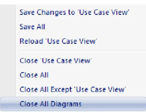
![Diagram Toolbox [Alt]+[5] Show or hide the Enterprise Architect UML Toolbox .](https://thumb-us.123doks.com/thumbv2/123dok_us/8556410.2311680/48.892.127.788.116.1068/diagram-toolbox-alt-hide-enterprise-architect-uml-toolbox.webp)