AG 31-004
School HVAC Design Guide
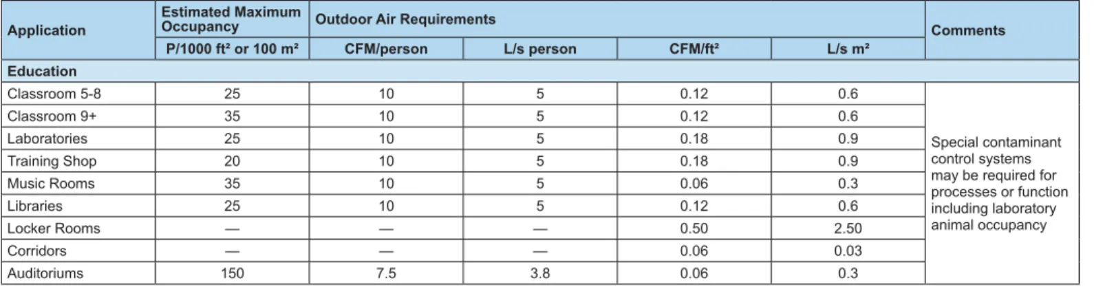
Boiler Chilled Water Pumps
Hot Water Pumps
Unit Ventilator Unit Ventilator Unit Ventilator
Air Cooled Chiller
Make up Water Line
Expansion Tank
HWR HWR
CHWR HWS
CHWS CHWS
CHWS
CHWR HWR
Introduction . . . . 3
History of School HVAC . . . . 4
General Issues . . . . 5
Room Design . . . 5
Load Calculations . . . 7
Regional Issues . . . . 9
Sound Issues . . . 9
Design Conditions . . . 15
Indoor Air Quality (IAQ) . . . . 18
Ventilation Rate Procedure . . . 19
Energy Efficiency
. . . . 21
Decentralized Systems . . . . 22
General . . . 22
Unit Ventilators . . . . 23
General . . . 23
Economizer Operation . . . 23
Draftstop
®. . . 26
Classroom Exhaust . . . 26
Unit Ventilators with Chillers and Boilers. . . 27
Piping Design . . . 29
Pumping Design . . . 29
Self-Contained Unit Ventilators . . . 30
WSHP Unit Ventilators . . . 30
WSHPs . . . . 31
General . . . 31
WSHPs for Classrooms . . . 31
Ground Source Heat Pumps . . . 33
Fan Coils . . . . 34
General . . . 34
Fan Coils for Classrooms . . . 34
Dedicated Outdoor Air Systems (DOAS) . . . . 36
General . . . 36
Outdoor Air Psychrometrics . . . 36
Energy Recovery Systems . . . 38
Central Systems . . . . 40
General . . . 40
Heating and Ventilating Systems . . . 41
VAV Systems . . . . 42
Duct Design Basics . . . . 46
Central System Equipment . . . . 47
Air Handling Units . . . 47
Chillers . . . 48
Rooftop Systems. . . 48
Vertical Self-Contained Systems. . . 49
Templifier
™. . . 50
HVAC Controls . . . . 51
Conclusion . . . . 52
Introduction
Studies have shown that the quality of our children’s
education is directly connected to the quality of the
classroom environment. It is incumbent upon school
officials, design engineers, architects and equipment
manufacturers to provide the best possible environment
that encourages learning. Sound, temperature, humidity
and Indoor Air Quality (IAQ) must all be balanced with a
fiscally and environmentally responsible solution.
The May 2003 ASHRAE Journal article by John Fischer
[ASHRAE 2003] quoting a 1995 General Accounting
Office survey [GAO 1995] of 10,000 schools in
5000 school districts reported about 50 percent of
the schools reported at least one unsatisfactory
environmental condition; while 33 percent reported
multiple unsatisfactory conditions. Of those, half
reported four to six unsatisfactory conditions. Those
conditions most frequently reported to be unsatisfactory
were acoustics for noise control, ventilation, and
physical security. Nineteen percent of schools surveyed
suffer from indoor air quality issues, and more than
one-third of the schools surveyed considered their
HVAC systems less than adequate.
Unfortunately, resolving the issue of poor IAQ in school
buildings can be costly for school building owners who
face multiple financial demands. The technologies
for solving issues of poor IAQ are well known and
adequately documented in the industry literature. When
school officials have the necessary resources to provide
good HVAC systems for their buildings they will always
choose to do so.
Good HVAC design includes consideration of premium
energy use efficiency as well. School buildings are
historically built for long service lives and school officials
are often just as concerned with long term operating
costs as the first cost of construction. As a class of
building types, school buildings have led the way in
high performance energy conscious design, even
approaching net zero energy building design.
This edition of the “School HVAC Design Manual”
expands upon the use of unit ventilators in class room
settings. It also looks closely at the issue of proper
humidity control in schools from several perspectives.
The purpose of this manual is to provide the design
engineer with a variety of HVAC solutions for classroom
environments. Issues such as IAQ, energy efficiency,
sound, complexity, serviceability, first cost and operating
cost will all be covered.
History of School HVAC
It was 1901 when J.H. Kinealy, President of the American Society of Heating and Ventilating Engineers, admonished the membership by saying: “ The heating engineer must have, to a certain degree, that kind of knowledge which a physician has in order to enable him to determine what are the effects of too high or too low a temperature upon the human body, what are the effects of too great or too small an amount of moisture in the air breathed by human beings, and what are the effects of impure air upon the health and wellbeing of the occupants of rooms. There are today many physicians who, either through old fogyism or lack of broad training, do not know what they should or at least do not advocate what should be advocated for the proper ventilating and heating of schools, hospitals and other building in which a large numbers of people are to be congregated for a considerable period of time… Heating engineers must be able to convince the physician that he knows what he is talking about and is right in what he says, or he must be able to convince those who have the deciding voice in the question of how a building shall be heated and ventilated.” Post World War II construction of school buildings brought new challenges to HVAC designers. Many ventilation system design strategies hadn’t changed significantly for decades and the mad rush to build more schools to house the baby boom children didn’t leave much time for careful thought on new designs. The most common solution was the application of the unit ventilator, which allowed simple design and convenient construction in a short time. Manufacturers produced vast numbers of these units in response to the growing demand and they evolved little until the 1990’s.
The energy crisis of the 1970’s did more to alter the school ventilation business than did the baby boom. Suffice it to say that most of the changes to rules and laws on ventilating school buildings owe, in large part, to the effects of the energy crisis. There was, however, some push back on the fast developing trend to cut ventilation rates in schools to conserve energy. After numerous schools developed problems with sick building syndrome and consequently sick children and teachers, the court system stepped in to curb the enthusiasm over eliminating outdoor air in school HVAC design.
A study done by doctors at the University Hospital in Uppsala, Sweden found a statistically significant correlation between the occurrence of asthma among school staff and the total concentration of mold organisms in the school air.
A large school district near coastal Texas suffered from
excessive mold growth in many school buildings due to summer cleaning with large quantities of water and a de-energized water chilling space conditioning system leading to significant excess moisture pooling in the spaces. [ASHRAE 2005]
General Issues
In North America, the typical school system consists of elementary schools (kindergarten to grade 6), middle schools (grade 7 to 9) and high schools (grades 10 to 12). Typically, 6 to 10 elementary schools feed 2 middle schools, which in turn feed 1 high school. Population density and demographics have a large impact on school planning.
Elementary schools consist of approximately 10 to 15
classrooms, an administration area, a gymnasium and a library. Elementary schools are used throughout the school season (late August to June), but see little use in the summer unless they hold summer school. They are generally occupied from 7:00 am to 3:00 pm.
A trend in elementary schools is to include science classrooms which require special consideration in design. Another popular trend is to attach a day care center to elementary schools. In most cases the day care centers are operated as a stand-alone facility and they require their own HVAC system.
Middle schools are larger than elementary schools. In addition to the facilities found in elementary schools, middle schools also have computer classrooms and locker rooms. Middle schools are open longer during the day than elementary schools due to extracurricular activities. Modern middle schools may contain a natatorium.
High schools can also include cafeterias, natatoriums, skating rinks, industrial shops, home economics rooms, stores and auto repair shops. Like middle schools, high schools are open longer during the day. In addition, high schools are often used in the summer, either for summer school or to make use of their special facilities (gymnasiums, natatoriums, shop facilities, etc.).
Colleges and technical schools are similar to high schools. They have similar facilities and are used year round. Night school programs extend the operating hours into the weekday evenings.
Many trends have emerged in recent years including a return to neighborhood schools and longer school years. Improved building design has made modern schools more airtight. These issues affect the decision making process for HVAC design.
Room Design
Classrooms are typically 900 to 1000 ft² (30’ by 30’) and hold approximately 20 to 30 students. At a minimum, the space must be heated and ventilated. Middle school and high school classrooms are typically air conditioned as well. In hot or humid climates, consideration should also be given to air conditioning elementary classrooms.
The classroom heating load usually peaks early in the day when the ventilation system goes into the occupied mode. Cooling loads usually peak late in the day.
Elementary classrooms generally have at least one exterior wall with windows. While modern construction resolves most infiltration and drafting issues, buildings constructed with older materials should be carefully evaluated for infiltration concerns. In addition, a washroom may be attached to each classroom, requiring local exhaust.
Middle and high schools may have classrooms that have only interior loads. Such classrooms will require year round cooling. Gymnasiums may be used in the evenings and on weekends. A dedicated HVAC system is recommended to deal with the range of loads and scheduling issues. If a wood floor is provided in the gymnasium, humidity control must be reviewed carefully with the flooring manufacturer to ensure the HVAC design will protect the floor.
Administrative areas are generally occupied before, during, and after school hours. To deal with the longer schedule, a dedicated HVAC system is recommended. In addition, because the occupancy level in the administrative area is lower than in classrooms, the outdoor air requirement is reduced. This should be considered in the selection of HVAC equipment to take advantage of first cost and operating cost opportunities. Administrative areas may be the only spaces within elementary schools that are air-conditioned.
Cafeterias and Auditoriums are often found in middle and high schools. Kitchens associated with the cafeterias required special ventilation and fire prevention equipment. NFPA requirements should be reviewed for such areas. Cafeteria and auditorium usage is tied to meal times and special events. Auditoriums may be required to operate in the evenings. Dedicated systems are recommended. Outdoor air ventilation systems are a special challenge because of the high population density when fully occupied. ASHRAE Standard
Science Classrooms can have very special HVAC needs depending on the range of work performed in the space. Elementary classrooms may only need additional ventilation for experimental demonstrations performed by the teacher, or any animals kept in the room.
Middle and high school science rooms may require fume hoods and makeup air systems with materials selected to withstand the chemicals used. Higher ventilation rates are also recommended to dilute odors. Material storage and preparation areas should be ventilated continuously.
Computer classrooms have high sensible heat gains from the computers and peripherals in the room. Humidification may also need to be addressed depending upon the equipment used in the classroom. Table 1 shows heat gains from Pentium grade computers and monitors.
Table 1: Heat Gains from Computers
Continuous (Watts) Energy Saver (Watts)
Average Value 55 20
Conservative Value 65 25
Highly Conservative Value 75 30
Small Monitor (13ʺ-15ʺ) 55 0
Medium Monitor(16ʺ-18ʺ) 70 0
Large Monitor (19ʺ-20ʺ) 80 0
Typical laser printers generate 215 watts during continuous use and 35 watts when idle.
Auto repair shops require outdoor ventilation and makeup air to dilute odors and fumes. Typically, shops are heated and ventilated but not air-conditioned. Return air from the shop should not be used in other spaces and the shop should be maintained at a negative pressure to contain odors. Because a shop can be used outside of regular school hours, a dedicated system is recommended. Special exhaust equipment to deal with welding fumes may also be required.
Ice rinks have special HVAC requirements in order to maintain a good ice surface without fogging, and to provide comfort for spectators. Ice rinks should have dedicated HVAC systems to accommodate their special requirements and extended operating hours.
School Stores are usually open for short periods of time. The HVAC system selection should accommodate the intermittent use.
Natatoriums have special HVAC needs. Humidity control from the pool surface is critical. Natatoriums should have dedicated HVAC systems designed for this application and to accommodate extended operating hours.
Industrial shops are similar to auto shops. Specialized equipment, such as dust collectors, may be required depending on the use. High sensible heat gains are possible due to machinery located in the space. A clear understanding of the machinery and its use will allow the designer to apply the proper diversity and avoid unnecessary first cost.
Locker rooms usually need to be exhausted directly to the outside if there are showers or toilets. As a result, makeup air is required to offset the exhaust. The space needs only heating and ventilation and the HVAC system be scheduled to shut down during unoccupied hours.
Home economics rooms can have high sensible heat gains from appliances. In addition, kitchen fume hoods and the appropriate makeup air may also be required. The space should be maintained at a negative pressure to contain odors.
Load Calculations
Accurate load calculations are critical to a well-designed HVAC system. Estimates for infiltration and drafting should be based on the actual school design, not on estimates from previous projects. Although some spaces will have high sensible heat gains, outdoor air will be the dominant load, particularly in modern buildings.
Figure 1 shows a classroom with southern exposure in the Chicago area. The classroom load peaks in September and the outdoor air load peaks in August. The HVAC system is decentralized with an energy recovery outdoor air system. Most of the outdoor air cooling occurs in the outdoor air unit (20% of the total load). Additional outdoor air cooling is required at the classroom unit (another 13%). The total outdoor air load is 33% of the classroom load.
The glass, wall and roof loads are much smaller. Even if they were larger (poor or older construction), the outdoor air load would still be the dominant parameter in the load analysis. The high population density should also be noted. The occupants represent 26% of the total load. Like the outdoor air load, this occurs in every classroom (North side, South side or in the core).
School loads differ from office building loads because of their low sensible heat factors (sensible cooling/total cooling). In
Figure 1, the sensible heat factor is 0.69. A typical sensible heat factor for offices is 0.90. Therefore, equipment designed for office environments will not be suitable for school environments.
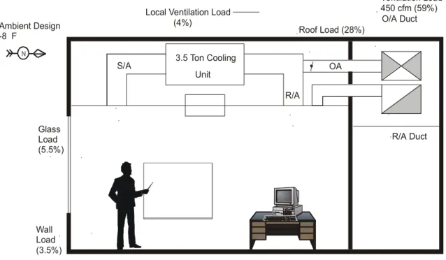
Figure 2 shows the same load breakdown but for heating. Again, the outdoor air load is dominant, representing 64% of the heat loss from the space.
An important conclusion can be drawn from these load calculations. All of the classrooms will behave approximately the same and their behavior will be dictated by the outdoor weather. Even larger schools with interior core classrooms will have similar characteristics. The details of just how the school zones will behave can only be found by performing the necessary heating and cooling load analysis.
Figure 1: Classroom Cooling Load Breakdown
Light Load (6%)
Electrical Load (6%)
Glass Load (19%)
EA OA R/A
S/A 3.5 Ton Cooling
Unit
Roof Load (10%) O/A Duct
R/A Duct Ambient Design
93 F db 75 F wb
Ambient at Peak Load (September)
91 F db
75 F wb Local Ventilation Load (13%)
Ventilation Load 450 cfm 82 F db, 67 F wb 14.2 mbh Load (20%)
Occupants (26%)
Figure 2: Classroom Heating Load Breakdown
Wall Load (3.5%)
Glass Load (5.5%)
EA OA R/A
S/A 3.5 Ton Cooling
Unit
Roof Load (28%) O/A Duct
R/A Duct
Classroom Corridor
Ambient Design -8 F
Local Ventilation Load (4%)
Ventilation Load 450 cfm (59%)
Regional Issues
Whether the school is located in Florida or Minneapolis has a large effect on the HVAC design. Humidity and
dehumidification concerns provide the widest range of issues. In humid climates, humidity control is critical to avoid mold growth and to provide good IAQ. Both the capacity and the operating mode of the HVAC equipment must be considered. A DX cooling system that is cycling OFF several times an hour will allow large volumes of humid air to enter the space during the OFF cycles. Although the equipment may meet the design cooling and dehumidification load, it fails to maintain a proper environment because of its operating mode.
Northern climates are concerned with freezing. Great care must be taken to avoid freeze-ups and the subsequent damage they can cause.
Most schools are designed by local engineers who are familiar with local issues. When designing projects in different areas of the country, special care must be taken to understand the needs of each local area.
Sound Issues
In recent years sound has moved to the forefront as a key parameter in the quality of the learning environment. Table 2 is the recommended sound levels from the ASHRAE Handbook.
Table 2: Recommended Sound Levels
Space A – Sound Levels dB (Noise Criteria)Desired NC
Libraries, classrooms 35–45 30
Laboratories, shops 40-50 35–50
Gyms, multipurpose, corridors 40–55 40–45
Kitchens, cafeterias 45–55 40
Source: 2015 ASHRAE Handbook
Classroom construction makes it more difficult to achieve low sound levels than in than in office spaces. There is little material to absorb sound energy and the hard, dense surfaces reflect sound energy back into the room.
Sound generating mechanical equipment (fan coils, watersource heat pumps, and fan powered VAV) should be located in the corridor where possible. Figure 3 shows the recommended duct design for a classroom. A return air elbow is recommended for all systems when a corridor ceiling plenum is used for the return air path. Fire dampers may be required in both the supply and return ducting, depending on the rating of the wall between the classroom and the corridor.
Special care should be taken in selecting diffusers. For a standard classroom of 1000 ft², four - diffusers are
recommended. If less than four diffusers are used, the required throw may make them too noisy. Most diffuser catalogs are based on only one diffuser in the space and a room absorption
Duct velocities should be limited to 800–1000 fpm to minimize sound issues. The supply duct should be acoustically lined for the first 10 ft. The return air elbow should also be lined. If duct lining is not acceptable, a sound attenuator with an insertion loss of 10 dB at 125 Hz is recommended.
Discharge and radiated sound from terminal equipment must also be carefully considered. Using cataloged NC levels for terminal equipment is not recommended. The assumptions made to derive NC levels are probably optimistic for classroom applications. Instead, use sound power ratings. Most terminal equipment manufacturers can provide both radiated and discharge sound power levels. For discharge sound power levels, 75 dB at 125 Hz and 72 dB at 250 Hz is recommended.
Figure 3: Classroom Duct Design for Good Acoustics
Minimum 4 Difusers
Lined S/A Duct
A/C Unit In Corridor
Lined R/A Elbow R/A
Horizontal Unit Ventilator Case Study
Two classrooms in an existing high school were retrofitted with horizontal unit ventilators (HUV).
Horizontal unit ventilators can and do make an impact on the noise levels in classrooms. However, the application of those units has a significant effect on their noise performance. The old HUVs which served the classrooms in this case study clearly influenced the quality of the noise environment and the new HUVs, in low speed, had much less effect on the noise environment while providing the same level of comfort air conditioning.
The existing HUVs were objectionable to the students and staff in the classrooms of this high school. Measured sound from these units showed the rooms noise was about 53 dBA. After the new Daikin Horizontal Unit Ventilators were installed as fully ducted concealed applications, the noise levels were reduced dramatically and, in low speed, met the requirements of ANSI S12.60-2002 as measured in a real classroom. Measured sound levels at low speed were within 2 dBA of the required 35 dBA in 5 out of 6 locations in one test room and in all locations in another test room. In high speed, the installed units demonstrated a reduction in noise levels from between 9.6 to 16.8 dBA depending upon the location in the room. Both rooms were equipped with 1500 cfm units. The ducts and diffusers were slightly oversized to reduce the noise and the ductwork was lined. An existing outside air sound attenuator was retained and eliminated the ambient airport noise from the rooms.
One test room, a science classroom, requires 1534 cfm of air at peak cooling load. The installed unit only saw less than a third of an inch of static pressure so was able to provide 1815 cfm at high speed. Most of the time, this classroom will be satisfied with the unit running at low speed. The low speed air volume delivered is 1258 cfm.
The second classroom is a small general purpose room that needs only 1376 cfm at peak load. Its new HUV is able to deliver this air even at low speed. At high speed, this unit delivers 1825 cfm at just over one quarter inch of static. The low static pressures are achievable in part due to the larger duct and diffuser size. Another feature was the removal of the air filters from the units and installation of new larger air filters in the oversized return diffusers and the outside air intake after the sound attenuator.
Existing Condition
Two existing HUV units were found to be installed partially below the ceiling of these two classrooms and were connected to respective sound attenuators at the outdoor air inlet. A local contractor was hired to install new AAF®HermanNelson
Classroom Ceiling Unit Ventilators in the two existing classrooms. They were piped up to the existing chilled and heating water and included their own self-contained controls with remote thermostat. See Figure 5 and Figure 6.
They were sized according to the load in the space and according to a desire for lower velocities in the unit, the ductwork and the diffusers.
NEW HUV
• Model No. U-AHB-6-H15-A-S-65-F-23-AH-29-G-W-B-1 • Ceiling mounted, face and bypass with reheat
• High static 1500 cfm nominal capacity • 115V/60 Hz /1 phase
• 3 row chilled water coil • 1 row hot water coil
• Fully ducted, supply, return and outside air with linked dampers
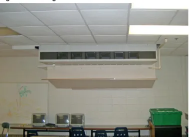
Figure 5: Existing Classroom 33 – HUV AAF Model AH-006
NOTE: The plenum houses an outdoor air sound attenuator
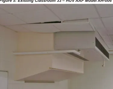
Figure 6: Existing Classroom 35 – AAF Model AH-006
NOTE: The plywood deflection for noise abatement. These units have water coils.
Figure 7: Schematic Plan for New HUV
RESULTS
Data Analysis
The existing HUV was objectionable to the students and staff in the test classroom. Measured sound from this unit showed the room noise was about 53 dBA. The sound pattern in Room 35 shows that the amplitude of noise varies with the location of the sample. The differences in amplitude by location are also not consistent with the frequency, suggesting that some frequencies reflect differently in the room. Figure 10 has amplitude sorted by the 4 kHz octave band and yet other octave bands show different amplitudes by location. Lower frequency bands have amplitude variability that is different than higher frequency bands. The higher frequencies may be influenced more by diffuser hiss and the lower frequencies by fan or duct rumble.
In every frequency, the actual measured sound is less than the tested sound generated by the HUV. This room attenuation is shown in Figure 9. Two noise criteria or NC curves are shown for comparison. The NC curves do not follow the generated or measured sound data but give a reference for design purposes. NC curves also do not offer any guidance on the quality of the sound. The HUV installed in this room suffered from poor quality as well as volume and this was more objectionable to the occupants. The plywood deflector shown in Figure 6 is an indication of the efforts of occupants to mitigate the objectionable sound quality.
Figure 9: Pretest of Old HUV and Two NC curves
Figure 10: Old HUV Room 35 in 1/3 Octave Band at all Six Locations 0 10 20 30 40 50 60 70
1 2 3 4 5 6 7 8
Octave Band
dB
NC 35 NC 25 Room 35 old Model AH Room Attenuation
NC 35 is about a 45 dBA NC 25 is about a 35 dBA Room average is about 53.33 dBA
8/13/2007 Pretest of existing AAF Model AH at Visitation School
Published sound data Measured sound data
LZeq 16Hz LZeq 25Hz LZeq 40Hz LZeq 63Hz LZeq 10 0Hz LZeq 16 0Hz LZeq 25 0Hz LZeq 40 0Hz LZeq 63 0Hz LZeq 1k Hz LZeq 1.6 kHz LZeq 2.5 kHz LZeq 4k Hz LZeq 6.3 kHz LZeq 10 kHz LZeq 16 kHz 2413 65 0 10 20 30 40 50 60 70
1/3 Octave Bands
2 4 1 3 6 5
dB
Presentation of Results
After installation, the new HUV were tested using the same instrument under the same conditions at the exact same locations as the pretest of the old HUV.
Figure 17 and Figure 18 show a comparison of the old HUV, the background noise with the room empty and no equipment operating, and the three speeds of the new HUV in each room. In both rooms, the high and medium speeds did not meet the ANSI 35dBA threshold. However, both rooms did meet the standard at low speed.
No classroom is ever totally silent as is shown by the
background noise data. Horizontal unit ventilators can and do make significant differences in the noise levels in classrooms. The old HUV clearly influenced the quality of the noise environment in these classrooms and the new HUV, in low speed, had little effect on the noise environment in these applications.
The answers to the questions of this study are these: 1. Proper sizing and installation of a horizontal unit
ventilator can result in classroom noise levels at or below the ANSI S12.60-2002 levels.
2. A properly sized and located sound attenuator, such as those already existing in this facility, can attenuate ambient noise from transportation to satisfactory levels. Unit Air Flow Performance
Each room HUV was tested for air flow and static pressure. Room 33 needs 1376 cfm at peak load (29,714 Btuh) and the HUV delivered 1825 cfm at 0.277 in. w.g. total static in high speed. Medium speed was 1586 and low speed 1376 cfm. Room 35 needs 1534 cfm at peak load (33,128 Btuh) and the HUV delivered 1815 cfm at 0.327 in. w.g. total static in high speed. Medium speed was 1477 cfm and low speed 1258 cfm.
Figure 11: Room 33 – New HUV Now Above Ceiling Existing Outdoor Air Attenuator Remained in Place
Figure 12: Room 33 – New HUV Diffuser Locations
Figure 13: Room 35 – New HUV Now Above Ceiling, Existing Outdoor Air Attenuator Remained in Place
Unit Sound Performance
Figure 15: Room 33 – Test Results (Data from Location 5 was Removed from the Summary)
Figure 16: Room 35 – Test Results
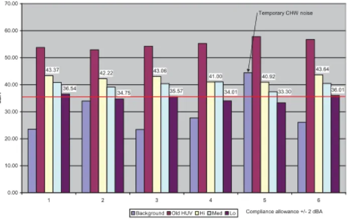
Figure 17: Room 33 – Summary of Average Sound
Figure 18: Room 35 – Summary of Average Sound
41.00 43.64 40.92 43.06 42.22 43.37 36.01 33.30 34.01 35.57 34.75 36.54 0.00 10.00 20.00 30.00 40.00 50.00 60.00 70.00
1 2 3 4 5 6
dBA
Background Old HUV Hi Med Lo
Temporary CHW noise
Compliance allowance +/- 2 dBA
37.73 35.69 35.69 41.35 40.84 41.93 31.94 30.97 30.72 33.94 33.43 34.8 0.00 10.00 20.00 30.00 40.00 50.00 60.00
1 2 3 4 5 6
dBA
Background Old HUV Hi Med Lo
28.95 50.99 55.46 61.92 35.17 54.55 40.04 57.92 42.50 59.56 35 55 0.00 10.00 20.00 30.00 40.00 50.00 60.00 70.00 dB
Background Old HUV Lo Med Hi ANSI dBA dBC 52.92 60.53 26.85 53.95 39.60 58.34 32.90 52.90 36.28 55.83 35 55 0.00 10.00 20.00 30.00 40.00 50.00 60.00 70.00 dB
Old HUV Background Hi Lo Med ANSI dBA dBC
Design Conditions
Table 3 lists recommended dry bulb temperatures from the ASHRAE handbook. For highly populated spaces, where the sensible heat factor is less than 0.75, lower dry bulb temperatures will result in less latent heat from the occupants. This may reduce the overall cooling and/or reheat requirement for the school. The actual dry bulb design condition should be carefully reviewed.
Dry Bulb Temperature
Recommendations
Table 3: Recommended Winter and Summer Design Dry Bulb Temperatures for Various Spaces Common in Schools
Space Winter Design (°F) Summer Design (°F)
Laboratories 72 78d
Auditoriums, Libraries, Administrative
areas etc. 72 78
Classrooms (Pre-K through 3rd) 75 78e
Classrooms (4th through 12th) 72 78e
Shops 72 78b
Locker, Shower rooms 75d c, d
Toilets 72 c
Storage 65 c, d
Mechanical rooms 60 c
Corridors 68 80d
NOTES:
b. Frequently not air conditioned. c. Usually not air conditioned d. Provide ventilation for odor control
e. if RH can be held between 30% and 60% then this can be 80°F
Humidity Control
In 1910, the Chicago Department of Health appointed a commission to study ventilation of school buildings. The commission’s report concluded that carbon dioxide was “not the harmful agent of major importance in expired air or air otherwise contaminated.” Instead, the report concluded that a temperature of 68°F with proper humidity control is desired in occupied rooms that are artificially heated and “that from the standpoint of health, relative humidity is one of the important factors in ventilation.” In spite of this report, the ventilation standards of the day only required minimum ventilation rates of outdoor air and not humidity control. [RH1]
Most cooling systems, when properly sized, can dehumidify room air when running at full-load conditions. Some systems are better suited than others to effectively dehumidify at part load conditions.
Cooling coils make good dehumidifiers. However, they can only perform when their temperature is continuously cold (< 55°F) and air is flowing over them continuously. Therefore, either chilled water or Direct Expansion (DX) coils will work well for dehumidification as long as they do not cycle OFF.
If a DX coil must cycle OFF, then the OFF cycle times must be as short as possible relative to the total cycle time. AHRI Guideline A recommends a minimum off cycle for refrigeration compressors of five minutes. A fifteen minute or longer “on” cycle and a five-minute “OFF” cycle is reasonable. (See
“Temperature Control” section) Another variation of the cycling DX coil is the two-stage coil. It is important to be aware of the method of splitting the coils to avoid a warm coil temperature. Coils that are “row-split” may have an average coil temperature warm enough to allow a high space relative humidity. A “face-split” coil will keep the active coil cold enough for good dehumidification. This arrangement is especially good when the air volume varies and the “dead” coil is isolated by dampers. An ideal DX system will modulate both the air volume and the compressor output to match the load continuously. A chilled water coil works well if it is served by a steady supply of continuously low temperature water. (<45°F) The chilled water coil must also be continuously cold. If the coil temperature rises from over-design air flow or low water volume the coil will become dry. Control systems that reset chilled water temperature upward should monitor the dew point temperature to lock out this reset until the ambient dew point falls below 55°F.
Dew Point Control
Dew point measurement is not very easy nor is it cheap. Nevertheless, it is the best method of controlling the humidity in a space. Relative humidity sensors, which are less expensive and widely available, become the control of choice for most school humidity control. Traditionally, RH sensors have had a roll in controlling humidifiers and economizers but they should also be used in cooling coil control.
Precise relative humidity control is not necessary for most education spaces. The comfort control range described above is quite broad at from 35°F DP to 65°F DP. This range also works well for minimizing the health effects. Relative humidity in the space can be allowed to float from 30% to 60% for most of the year and as low as 20% in the depth of the winter. Below 20% the controls should conserve moisture generated from the space as much as possible.
“Free Cooling” economizers can actually do more harm than good in some circumstances. Even enthalpy controlled economizers may load up a space with moisture. A better solution is to set any economizer control so it never uses outdoor air with a higher dew point than the level desired in the space. From the previous paragraph, a dew point control should lock out the economizer when the ambient dew point was above 65°F regardless of the dry bulb temperature.
Temperature Control
Space temperature control of cooling coils turns out to be a relatively poor choice for dehumidification of a space. Cooling coils that are controlled only by space temperature may deliver air with high dew points potentially loading up the space with moisture. Chilled water flow control in cooling coils may be reduced to the point where dehumidification stops completely. Direct expansion coils will cycle OFF for long periods of time during periods of low sensible loads.
DX systems have an additional problem with part load conditions. As unitary equipment becomes more energy efficient, their cooling coils have a lower capacity to remove moisture at part load conditions. An important variable appears to be the greater fin surface area of newer, higher efficiency cooling coils compared to those from 20 years ago. These larger fins can store more moisture before it runs off into the drain pan. Research has shown that coils from the 1980s typically store 200 runtime seconds of moisture on their fins and 1996 coils can store 720 runtime seconds of moisture. This is why DX coils have trouble with moisture removal unless they have run times of fifteen minutes or more. Continuous fan operation without continuous coil operation may re-evaporate this stored moisture. Intermittent fan operation will reduce this re-evaporation if the OFF cycle is relatively short.
Systems
Simple Design Rules: Classroom ventilation systems typically used by designers can be capable of providing dehumidification. All system types should follow these simple rules:
• Size cooling for the ventilation latent and sensible load (See “Loads”)
• Provide a trap on the condensate drain for all draw-through units
• Provide relative humidity sensing and control of the cooling coil (Measure RH from one or more rooms directly if possible)
• Provide minimum outside air quantities to comply with the building codes
• Provide reheat or desiccant moisture removal with more than 75% site recovered energy
• Control space relative humidity to 60% max
Loads: The moisture load calculation represents an agreement between equipment supplier, system designer, owner, and contractors. This agreement defines the assumptions that form the foundation of the system design. Ventilation, infiltration and people generate the principal moisture loads in a classroom. The largest load is the ventilation air, which will be nearly constant when the room is occupied. Other loads from people and wet material are intermittent. If the system is not able to remove all of this moisture at peak times, the excursion will be short lived as long as the system has the capacity to keep up with the continuous ventilation load. Therefore, the cooling coil of any classroom system should be sized for the expected ventilation latent and sensible load.
Humidity Range
Both low and high humidity levels are concerns. Figure 19 shows the Sterling bar graph from the 2000 ASHRAE handbook indicating how high and low humidity levels affect key health factors.
Humidification in dry climates is not mandatory, but it will improve the environment for the occupants. Dehumidification in humid climates is a larger concern because potentially harmful microbial can grow in damp locations. The HVAC system should be designed to maintain the relative humidity between 40 and 60% throughout its entire operating range.
Figure 19: Sterling Bar Graph
System Complexity
The requirements of good indoor air quality, comfort, energy efficiency and acoustics can lead the designer to some very complex HVAC solutions. Because school districts represent owner occupied customers, the school district’s ability to support the system must be considered in the design of the HVAC system. If the system becomes so complicated that no one can operate it, then the designer’s efforts have been in vain. The designer should understand and appreciate the skills and limitations of the school district that will operate the system, and this should be taken into account when selecting the HVAC system.
Serviceability
In addition to operating the HVAC system, the school district will also have to maintain it. They are acutely aware of the maintenance costs associated with operating schools and will highly value serviceability.
Allergic Rhinitis & Asthma Bacteria Viruses Fungi Mites
Respiratory Infections
Chemical Interactions Ozone Productions
Optimum Zone
Indoor Air Quality (IAQ)
Schools present unique challenges for achieving good IAQ. For example, the population density of an average classroom (900 ft² classrooms with thirty students) is three times that of a typical office.
ASHRAE has developed Standard 62.1, Ventilation for Acceptable Indoor Air Quality. It is in normative (code
enforceable) language and has become the minimum standard of care in most building codes.
Standard 62.1 provides two procedures to obtain acceptable indoor air quality. Table 4 represents the ventilation rate procedure, which is the most popular. There is also the Indoor Air Quality Procedure. The later requires identifying and controlling known and specifiable contaminants.
The minimum outdoor air rates listed in Standard 62.1 represent the minimum supply air volume to the space. The total supply air can be made up of the minimum outdoor air and acceptable recirculated air. It is acceptable to supply more air to meet the heating or cooling loads.
The HVAC system design must be able to maintain space temperature and humidity conditions at the minimum outdoor air rate. For example, with a VAV system, the minimum airflow rate for the VAV box must be the minimum outdoor air rate for the classroom. During certain periods, this may be too much air and the classroom will be over cooled. In this case, some form of reheat would be required rather than reducing the airflow. Ensuring the proper amount of outdoor air is brought into the school is only the first step. It is essential that the correct amount of outdoor air be delivered to each space. Dedicated makeup air systems can be ducted directly to the terminal unit (fan coils, WSHPs) and an air balance performed to ensure proper distribution.
Table 4: Outdoor Air Requirements for Ventilation from ASHRAE Standard 62.1
Application Estimated Maximum Occupancy Outdoor Air Requirements Comments
P/1000 ft² or 100 m² CFM/person L/s person CFM/ft² L/s m²
Education
Classroom 5-8 25 10 5 0.12 0.6
Special contaminant control systems may be required for processes or function including laboratory animal occupancy
Classroom 9+ 35 10 5 0.12 0.6
Laboratories 25 10 5 0.18 0.9
Training Shop 20 10 5 0.18 0.9
Music Rooms 35 10 5 0.06 0.3
Libraries 25 10 5 0.12 0.6
Locker Rooms — — — 0.50 2.50
Corridors — — — 0.06 0.03
Ventilation Rate Procedure
The amount of air that needs to be brought into a central AHU is called the outdoor air intake flow. (Vot ).
The amount of iar that needs to be delivered to the breathing zone in an occupied space is
V
bzThe
V
bz is the sum of the air for people plus the air for the building calculated in an equation derived from the concept of additivity.V
bz= R
p× P
z+ R
a× A
z where:V
bz is the breathing zone ventilation rate (cfm)R
p is the ventilation rate per person from Table 4 (cfm/person)P
z is the number of people in the zoneR
a is the ventilation rate per square foot in the zone (cfm/sf)A
z is the area in the zone (square feet)Some air distribution systems are better at delivering outdoor air to the breathing zone for people than others. So the system airflow needs to be corrected for poor air distribution.
V
ot= V
ou/ E
vwhere:
V
ou= D Ʃ
all zonesR
pA
z+ Ʃ
all zonesR
aA
zD = P
sƩ
all zonesP
zP
s is the total populationin the system’s areaV
ot is the design outdoor airflow to the system air handling unitE
v is the zone air distribution effectiveness for variousdistribution systems varying from 0.5 for a system that has significant short circuiting of air to 1.2 for displacement distribution. (See Table 6.2.25.2 in Standard 62.1-2013)
Demand Control Ventilation (DCV) allows the amount of outdoor air to modulate to meet the needs of the space. Typically they are used in spaces where the population density varies significantly. Carbon Dioxide (CO2) is an excellent
measure of the amount bio effluents in the space. People give off CO2 and bio effluents at a rate proportional to their activity.
To design a DCV system, determine the design outdoor air rate without any diversity. Locate CO2 sensors in the space or
the return air duct for single zone systems. For multiple zone systems, CO2 sensors must be in every zone, or at least those
zones considered critical.
Calculate the maximum CO2 concentration level allowed.
Typically this is around 1000 ppm with ambient CO2
concentrations around 300 ppm. An outdoor CO2 sensor is not
required if a conservative ambient level is used.
The minimum ventilation rate must be maintained regardless of CO2 levels. This rate is meant to account for contaminants
from building materials, carpeting, etc. The current Standard 62.1 does not provide this minimum level. It is proposed in an upcoming addendum.
A thorough explanation of the Standard is beyond the scope of this manual. It is recommended that the designer have access to the Standard and a complete understanding of its contents. ASHRAE considers Standard 62.1 a high profile standard and has it on continuous maintenance, meaning it is constantly improved rather than being reissued every 5 years.
Energy Efficiency
After payroll, the utility bill is the next largest expense for a school district. Modern construction materials and techniques help reduce the energy bill. High efficiency lighting also has a large impact on reducing the utility bill. The last big opportunity for savings is the HVAC system – particularly the outdoor air system.
ASHRAE Standard 90.1, Energy Standard for Buildings Except Low Rise Residential Buildings is a normative (code enforceable) Standard endorsed by the Department of Energy (DOE). It has become the minimum standard of care for most building codes.
The standard was updated in 2013. The new version
represents a significant energy improvement from the previous standard. Improvements to mechanical systems represent a major portion of the improvement.
Standard 90.1 offers two approaches to the school designer. There is also a third approach for small buildings that is generally not applicable to schools. The more popular approach for schools is the Prescriptive Method. This method provides procedures for designing the building envelope, HVAC, service water heating, electrical power, lighting and electrical motors. The standard requires all the general and mandatory provisions be met.
The other approach is the Energy Cost Budget (ECB) method. This method allows the designer to make tradeoffs. For example, the ECB method would allow the savings from more efficient lighting be used to offset a building envelope that does not meet the prescriptive method.
The following is an abbreviated list of requirements for the prescriptive method outlined in Standard 90.1. The numbers in brackets refer to the Standard section.
1. Standard 90.1 includes energy efficiency tables for a wide range of HVAC equipment.
2. Schools are ideal candidates to schedule the HVAC equipment to be off during unoccupied hours. Standard 90.1 mandates that this process be automated (6.4.3.3). 3. Demand Controlled Ventilation is required for systems
with occupant density greater than 25 people per 1,000 ft² (6.4.3.8).
4. Air or water side economizers are required. There are several exceptions to this rule, particularly when dealing with heat recovery (6.5.1).
5. Simultaneous heating and cooling systems such as constant volume terminal reheat, some perimeter induction systems, constant volume dual duct or multizone systems are not permitted. These systems,
7. Reheat is also allowed if at least 75% of the energy for reheat comes from on-site energy recovery (Templifiers). 8. WSHP systems must have either a bypass line around
the cooler or low leakage positive closure dampers on either the cooler inlet or discharge (6.5.2.2.3).
9. Fan motor horsepower is limited to values listed in Table 6.5.3.1-1 in Standard 90.1. The limitation applies to the sum of all fan motors in a system such as supply, return/ relief, exhaust and fan –powered terminal units. Small exhaust fans less than or equal to 1 hp are exempt. Spaces requiring pressure control such as hospital, laboratory, and vivarium are exempt. The limitation applies to either the brake horsepower or the nameplate horsepower at the designers discretion. The limitations vary between constant and variable volume fan systems. 10. Hydronic systems with a system pump power that
exceeds 10 HP must employ variable flow and isolation valves at each terminal device. The system must be able to operate down to at least 50% of design flow. Individual pumps over 5 HP must have VFDs and consume no more than 30% design power at 50% design flow (6.5.4.2).
11. Supply temperature reset is required for hydronic systems larger than 300 MBH. Temperature reset is not required if it interferes with the proper operation of the system i.e. dehumidification (6.5.4.4).
12. Fan motors on cooling towers larger than 7½ HP must either have VFDs or be two speed. A control system is required to minimize power usage (6.5.5.2).
13. Energy recovery is required for systems listed in Tables 6.54.6.1-1 and -2 in the standard. These tables indicate by climate zone and outside air percentage which air handling and conditioning systems require heat recovery. The heat recovery system shall have at least 50% total energy recovery effectiveness. (6.5.9).
14. Hot Gas Bypass for refrigeration systems is permitted, but has strict limitations (6.5.6.1).
A thorough explanation of the Standard is beyond the scope of this manual. It is recommended that the designer have access to the Standard and a complete understanding of its contents. The Standard 90.1 User’s Manual is also very helpful. ASHRAE considers Standard 90.1 a high profile standard and has it on continuous maintenance, meaning it is constantly improved rather than being reissued every 5 years.
Decentralized Systems
General
Decentralized systems include Unit Ventilators, WSHPs and fan coils. Each zone is typically handled by a dedicated unit, allowing one zone to be in heating while another is in cooling. Equipment failures only affect one zone. Scheduling can be zone-specific allowing for increased operating savings. Decentralized equipment is generally straightforward to service and can be a major advantage in rural areas. Some decentralized equipment can rival the most advanced built up systems for energy efficiency.
Disadvantages to decentralized systems include maintaining equipment spread throughout the building, often in occupied spaces. Equipment life is generally shorter and locating mechanical equipment at or near the occupied space can make sound an issue must be dealt with.
Unit Ventilators
General
Unit ventilators are the only HVAC system specifically designed for schools, and they condition more classrooms than any other HVAC system. The inclusion of an airside economizer, guarantees proper ventilation is introduced directly into the classroom. The four pipe version is one of the most energy cost effective systems because the fan power is very small. Unit ventilators are robust enough for the classroom
environment and come in a wide variety of configurations. They have integral airside economizers that allow the unit to provide up to 100% outdoor air directly into the space. They can be horizontal or vertical, and they can have steam, hot water or electric heating plus chilled water integral or remote DX cooling. There are also airside heat pump and WSHP versions. Modern unit ventilators come with sophisticated DDC controls that can maintain space conditions, operate the outdoor air/economizer section and schedule operation. With this capability, they can be integrated into a building automation system (BAS).
Figure 20: Unit Ventilator
Economizer Operation
There are two key properties of unit ventilators: institutional quality construction and an integrated economizer. The
institutional quality construction is aimed at withstanding use and abuse in the classroom environment. The economizer allows the unit ventilator to locally accommodate the IAQ needs of the classroom by introducing the necessary outdoor air.
Figure 21 shows the unit during full recirculation. This is the unoccupied mode. Only return air passes through the unit. The classroom can be maintained at either classroom conditions or unoccupied (setback) conditions without the expense of conditioning any outdoor air.
Figure 22 shows a draw through fan arrangement unit ventilator with Face and Bypass temperature control during the economizer mode. In this arrangement, the outdoor air and return air are mixed and then flowed around and through the coil(s) to maintain the proper room setpoint. The conditioned air is then delivered into the classroom
Figure 23 shows the same unit in full cooling or heating. During full heating or cooling, the outdoor air drops to the minimum design level (typical to around 450 cfm). Here again, the outside air and return air are mixed and then flowed around and through the coil and into the space.
Figure 24 shows the unit ventilator during full economizer
If the classroom temperature is set back or up, the recirculation mode can be used to quickly get the room to occupied
conditions by cooling or heating 100% of the recirculated air.
Figure 22: Face and Bypass Mode
Figure 23: Full Heating or Cooling Mode
Face and Bypass vs . Valve Control
The above examples use the preferred method of face and bypass control. The other common control strategy is valve control. In unit ventilators with valve control, the space
temperature is maintained by modulating a control valve. While valve control does maintain the dry bulb setpoint and is a necessary building block for variable flow systems, it is not as effective as face and bypass control in humid or cold climates.
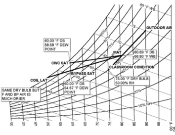
Figure 25 demonstrates the difference between valve control and face and bypass control on a psychometric chart. At part load operating conditions, the valve control approach, provides the same dry bulb conditions, but not the same level of dehumidification. With the face and bypass arrangement, the air that passes through the cooling coil is significantly dehumidified. When this air mixes with the bypassed air, the dry bulb setpoint is met and the wet bulb is lower than the control valve arrangement.
Cold weather climates also benefit from the face and bypass approach. The high percentage of outdoor air can make coil freezeups a concern. Valve control lowers the water velocity in the tube, which can lead to coil freezeups. This can be further exacerbated by poor control valve selection. If the valves are incorrectly sized, they may not modulate the fluid flow, but cycle like an ON-OFF valve. The face and bypass arrangement maintains full flow through the coil to protect it from freezing. When valve control is used, correct valve selection is critical for proper unit operation.
While Daikin Unit Ventilators are offered with both control options, face and bypass is strongly recommended. End-of-cycle isolation valves are available to automatically close off flow to the coil when it is no longer required.
Figure 25: Face and Bypass vs. Control Valve
Draw Through vs . Blow Through
The draw through fan arrangement in unit ventilators offers two key advantages. The first is even air flow across the coils. This is important because the unit ventilator cabinet is more confined than a central station air handling unit, making airflow transitions difficult. The second advantage is that the fan motor heat is added after the cooling coil. The high latent load found in classrooms makes adding the motor heat as reheat more attractive.
Draftstop
®
Classrooms with exterior exposures typically have large windows. This can cause drafting in cold climates, especially for students located near the windows. Older schools with less efficient glass are also a concern. A Draftstop system can be used to reduce drafting.
Figure 26 shows how Draftstop collects the air from around the window and delivers it to the unit ventilator. The air is then conditioned and returned to the classroom.
Figure 26: Draftstop System
Classroom Exhaust
A typical occupied classroom needs to exhaust a minimum of 450 cfm to offset the 450 cfm of outdoor air. There must be a way to remove the exhaust air from the classroom or the required ventilation will not be met.
Figure 27 shows a Ventimatic shutter, which can provide local relief for a classroom. Another possibility is to have central exhaust fan ducted to four to six classrooms. During occupied hours, the fan operates and removes the required exhaust from each classroom If a classroom is used after regular hours, the exhaust fan can be left off to allow the exhaust air to vent into the corridor. The exhaust fan can also be interlocked with the unit ventilators and operated when any of them require exhaust air.
Figure 27: Ventimatic Shutter
Steel Interior Wall Grille (Optional)
Unit Ventilators with Chillers and Boilers
Using a central chiller plant and boilers in combination with unit ventilators can be more energy efficient than self-contained dx systems. Unit ventilators with one or two water coils are the most common arrangement. Single coil (2 pipe) units can provide heating and ventilating only, or heating with a changeover to cooling. Units with dedicated heating and cooling coils (4 pipe) offer excellent performance.
Using a central chiller and boilers offers many advantages. The chiller and the boilers can be sized for the school block load rather than the connected load. Taking into account diversity allows for smaller chiller/ boiler plants. The piping and pump horsepower required to heat and cool the school significantly smaller than the equivalent air duct and fan horsepower. Finally, chilled water and hot water offer accurate control with either face and bypass or valve control. Sound issues are also simplified with chiller and boiler plants.
Either air-cooled or water-cooled chiller plants can be used.
A central boiler plant can operate on natural gas or other primary energy source and modern condensing boilers with efficiencies over 90% can be used. The hydronic heating loop can be used in entrances with convectors and cabinet heaters rather than electric heaters. The boiler plant can be located in a safe remote mechanical room.
With a four-pipe system the classroom unit control is an airside economizer with either valve control or face and bypass. Two pipe heating and ventilating units have been an excellent choice for elementary schools in moderate climates. The schools have traditionally seen little occupancy during the summer, so cooling was not mandatory. The shoulder seasons can usually be handled by the economizer operation inherent in a unit ventilator. The current trend is towards longer school seasons and air conditioning even in elementary schools. Four pipe units allow some classrooms to be in cooling mode while other classrooms are in heating. This is especially advantageous for schools with core area classrooms that require cooling while perimeter classrooms need heating. Four pipe systems require an additional set of insulated piping, another set of pumps and a second coil in the unit ventilators.
Figure 28: Four Pipe System
Boiler Chilled Water Pumps
Hot Water Pumps
Unit Ventilator Unit Ventilator Unit Ventilator
Air Cooled Chiller
Make up Water Line
Expansion Tank
HWR HWR
CHWR HWS
CHWS CHWS
CHWS
CHWR HWR
Two-Pipe Changeover System
Two-pipe changeover systems reduce the first cost of the system by deleting one set of insulated pipes and one set of pumps. The unit ventilator price is also reduced as there is only one coil required. This can reduce the construction cost by 25% over the four-pipe arrangement.
The first cost and operating cost savings are desirable but some performance benefits are lost with the two-pipe concept. It is no longer possible to have one unit ventilator in cooling while another is in heating. In addition, dehumidification by means of reheat is not possible. With proper design, these issues can be minimized.
Simultaneous heating and cooling cannot occur in a two-pipe system which is energy efficient. However, during changeover, the hydronic system must be either heating or cooling which is not energy efficient. To deal with this issue, ASHRAE Standard 90.1 has specific requirements for changeover systems. These are:
a. There must be a deadband in the changeover of at least 15°F outdoor air temperature.
b. The system must be designed and installed with controls that allow operation in one mode for at least 4 hours before changing back to the other mode.
c. Reset controls are provided that allow the hot water and chilled water setpoints to be no more than 30°F apart at changeover.
In addition to energy concerns, the changeover period raises comfort concerns. What if the classroom on the north side requires heating while the classroom on the south side requires cooling? The main HVAC loads in a modern classroom are outdoor air (33%) and internal heat gains (38%). These two factors are constant in all classrooms throughout the school regardless of the shoulder weather. The remaining load from the roof, walls and glass represents 29% and can vary depending on the zone. With only these loads as variable and the economizers in unit ventilators, dealing with the transition is possible.
The first requirement of Standard 90.1 is a 15°F ambient deadband. Providing stable space conditions while maintaining the deadband can be accomplished with economizers. For example, a deadband of 15°F from 50°F ambient to 65°F ambient meets the requirement. Figure 30 shows the mixed air temperature as the ambient temperature drops. At 65°F ambient, the economizer can supply air from 65°F (100%
The second requirement of Standard 90.1 is the 4 hour deadband. Since two thirds of the load is ambient and internal heat gains, all the classrooms will behave approximately the same. Swings from heating to cooling or visa-versa are not likely unless there are radical changes in the weather. The last issue is the 30°F deadband. Resetting the chilled water up to 50°F and the hot water down to 80°F will meet the requirement. Resetting the hot water also resolves an issue with the coil, which has to be selected to meet the more demanding role of cooling and will be oversized for heating. An oversized coil will lead to control problems and poor space temperature control. By using a condensing boiler, the heating loop can be operated at 80°F and modulated up with an outdoor air reset controller. The lower temperature will allow good space temperature control.
School layout and orientation also play a key role in assessing how the school will perform during the transition period. The school layout may be such that one block or wing of classrooms will behave differently than another block of classrooms. This can be resolved by having two loops, one serving each block of classrooms.
Figure 29: Mixed Air Temperture
50 55 60 65 70 75 80
30 40 50 60 70 80
Ambient Temperature M ix ed A ir T em pe ra tu re
Piping Design
Piping design for unit ventilators is straightforward as long as good piping practice is followed. For chilled water and hot water systems, ASHRAE Standard 90.1 has specific pipe insulation requirements. Reverse return piping is favorable due to its inherent self-balancing. However, direct return piping is possible. Proper balancing valves should be installed to allow the system to be balanced.
Traditional operating conditions are 44°F EWT/ 54°F LWT for chilled water and 180°F EWT/160°F LWT for boiler loops. For chilled water, these temperatures result in 2.4 USGPM/ton. For heating, the result is 1 MBH per USGPM. Using larger delta T’s for the water loops reduces first cost (smaller piping and pumps) and operating cost (lowers horsepower). However, it usually hurts equipment performance by lowering the LMTD (Log Mean Temperature Difference). Careful evaluation is required to determine the best operating temperatures and flow rates.
In the case of two pipe changeover systems, the flow should be based on the chilled water flow rate. Variable flow design can lower the flow rate for heating.
Central chilled water and boiler plants allow the designer to apply diversity to the load. Whether the diversity is applied to flow or temperature range will depend on the plant design and valve selection.
For boilers, a high efficiency, condensing boiler is the best choice. The condensing boiler efficiency is over 90%, which will lower the school operating cost. They can be selected in modules to provide staging and redundancy. In addition, condensing boilers require no circulating boiler pumps and they have a very small footprint. This allows the mechanical room size to be reduced as an added benefit to school administrators. Proper flushing of the piping system is critical to the correct operation of the system. If the system is not properly flushed, the contaminants can lodge in the small heat exchangers used in decentralized equipment which can be extremely difficult to resolve.
Pumping Design
In most cases, some form of redundant pumps is preferred. This can include two pumps, each sized for the load with one as a standby. It can also include three pumps, each sized for half the load, with two operating and one as a standby. All pumps should have a check valve on their discharge line and strainers on their suction lines.
ASHRAE Standard 90.1 requires hydronic systems with system pump power exceeding 10 hp to employ variable flow and isolation valves at each terminal device. The system must be able to operate down to at least 50% of design flow. Individual pumps over 5 HP must have VFDs and consume no more than 30% design power at 50% design flow. The Standard has some exceptions to this requirement.
For variable flow, two-way control valves are required. Three-way valves are not acceptable. A bypass will also be required to maintain minimum flow. Minimum flow will be dictated by the requirements of the chiller or boiler plant, and will likely be 33% or more. For a variable frequency drive, horsepower savings are minimal below 20Hz due to motor inefficiencies.
Face and bypass systems should be installed with end-of-cycle shutoff valves so that variable flow can be accomplished. Varying the system flow can be accomplished several ways. If the three pump approach is used (two operating, one as a standby), then one of the pumps can be turned OFF at reduced demand. Two speed pumps or variable frequency drives can also be used.
Self-Contained Unit Ventilators
Self-contained unit ventilators do not require chilled water plants. They include DX cooling, either completely integrated into the unit or as a split system with an air-cooled condenser nearby. The advantage of this approach is overall first cost, reduced complexity and no requirement for a chiller mechanical room.
The disadvantages of self-contained units are lower energy efficiency, poorer space control (particularly in dehumidification) and no way to take into account cooling diversity. More tons of cooling will have to be purchased for a school using the self-contained approach than for a school based on a central chiller plant. In addition, sound can be a concern because the units may have compressors located in the classroom.
Heating can be hot water, steam or electric. Integrated self-contained units can also be air-to-air heat pumps, greatly improving their energy efficiency but also requiring more operating hours for the refrigeration circuit. Air-to-air heat pumps are popular in warmer climates where the heating requirements are less. Supplemental heating may be required if the ambient conditions stay below freezing for any length of time.
Self-contained unit ventilators are an excellent choice for small to medium size elementary schools where cooling is required. Electric heat self-contained units are well suited for portable classroom applications as well.
Figure 30: Self-Contained Unit Ventilator
WSHP Unit Ventilators
Unit ventilators can also be supplied as a water source heat pump (WSHP) or as a ground source heat pump. This approach allows the designer to have WSHPs with built in airside economizers. Further energy savings can be realized by using ground source to eliminate the need for a boiler and closed circuit cooler.
The next section describes the WSHP design concept in detail. However, WSHP unit ventilators have some unique properties. Since the coil is refrigerant-cooled and heated, face and bypass is not possible. There are also limits on the heating capacity of WSHP unit ventilators. As a rule of thumb, the unit ventilator can work down to about 15°F ambient. Further care must be taken to protect the heat pump water loop from freezing.
Ground source heat pump unit ventilators do not have loop freezing issues as the loop will have some form of antifreeze. The designer should discuss what kind of antifreeze to use with the school board. Concerns about toxicity, performance and environmental issues will need to be reviewed.
Ambient conditions that exceed the heating capacity of the unit ventilator will require either supplemental heating (a small electric heater) or a central system to deal with outdoor air. If a central system is used, it does not have to be sized for all of the outdoor air. Depending on the site conditions, it may only need to be sized for half of the outdoor air with the WSHP unit handling the balance of the outdoor air requirement.