POLON 4000
INTERACTIVE FIRE DETECTION AND ALARM SYSTEM
POLON
4100
FIRE
DETECTION
AND
ALARM
ADDRESSABLE
CONTROL
PANEL
Operation
and
Maintenance
Documentation
ID
‐
E342
‐
001GB
IB
Edition
The POLON 4100 fire detection and alarm control panel covered by the present manual, complies with the requirements of the following European Union Directives:
CPD 89/106/EWG on construction materials;
EMC 2004/108/WE on electromagnetic compatibility
LVD 2006/95/WE on low‐voltage electric equipment.
The POLON 4100 addressable control panel has been attested with the EC‐Certificate of Conformity
No. 1438/CPD/0179 issued by the Scientific and Research Centre for Fire Protection (CNBOP)
Józefów, Poland, a EU notified authority No. 1438, confirming its compliance with the requirements of 54‐2:2002+A1:2007 standard.
The device has been also approved with the Allowance Certificate No. 0715/2010 issued by CNBOP.
The certificates may be downloaded from www.polon‐alfa.pl web site.
1438
Polon‐Alfa Spółka z ograniczoną odpowiedzialnością Sp. k. 155, Glinki Street, PL 85‐861 Bydgoszcz, POLAND
10 1438/CPD/0179 EN 54‐2:1997+A1:2006
POLON 4100 Fire Detection and Alarm Control Panel Addressable, for indoor use
Provided options:
‐ fire alarming devices output ‐ output signal delays ‐ interdependent alarming ‐ testing mode
‐ alarm counter
and additional functions, inputs and outputs: see technical data contained in ID‐E342‐001GB manual
Read the manual carefully before the detector assembling and commissioning.
Any nonconformity with the instructions contained in the manual may be harmful or may cause
violation of the law in force
POLON‐ALFA bears no responsibility for any damage resulting from usage inconsistent with the
manual.
A waste product, unsuitable for further use, shall be passed to
a waste electric and electronic equipment collection point.
NOTE: The manufacturer reserves the right to change specifications of products at any time
CONTENTS
1 INTRODUCTION ... 6
1.1 Documentation contents ... 6
1.2 Control panel application ... 6
1.3 Safety conditions ... 6
1.3.1 Electric shock protection ... 6
1.3.2 Installation and equipment safety ... 6
1.3.3 Repairs and maintenance ... 7
1.4 Definitions ... 7
2 DEVICE COMPLETENESS ... 8
3 TECHNICAL SPECIFICATIONS ... 9
4 DESIGN DESCRIPTIONS ... 11
4.1 Overall control panel description ... 11
4.2 Module arrangement ... 12
4.3 Handling and signalling elements ... 12
4.3.1 Optic LED indicators ... 12
4.3.2 Control panel handling and signalling elements ... 13
4.3.3 Numeric keypad and edition push buttons ... 15
5 OPERATION DESCRIPTIONS ... 16
5.1 General description ... 16
5.2 PSC‐41 central controller module ... 18
5.2.1 Module signalling and handling elements ... 18
5.3 MLS – 41 line‐controlling module ... 19
5.4 Addressable detection lines ... 20
5.4.1 Detection lines types ... 20
5.4.2 Addressable elements numbering ... 23
5.5 Design guidelines ... 23
5.6 Inputs‐outputs ... 24
5.6.1 General description ... 24
5.6.2 PK relay and LS signal outputs ... 24
5.6.3 Fire alarm transmission device output (TYPE 1) ... 25
5.6.4 Fire alarm transmission device output (TYPE 2) ... 26
5.6.5 Protective device output (TYPE 3) ... 27
5.6.6 Fault/technical alarm signalling output (TYPE 4) ... 27
5.6.7 Information output (TYPE 5) ... 28
5.6.8 Reset output (TYPE 6) ... 28
5.6.9 LK monitoring output ... 28
5.6.10 Serial ports... 32
5.6.11 TSR‐4000 terminal output ... 33
5.6.12 Computer keyboard output ... 33
5.7 Power supply ... 33
5.8 Control panel interoperation with battery panel ... 34
6 ALARMING SYSTEM/STRUCTURE ... 34
6.1 Detection zone ... 34
6.2 Addressable elements declaration ... 35
6.3 Assigning alarming parameters to zones ... 35
6.4 EKS‐4001 monitoring and controlling elements declaration ... 36
6.5 EWS‐4001 multi‐output controlling elements declaration ... 40
6.6 Multi‐output controlling elements declaration ... 42
6.7 SAL‐4001 acoustic signalling devices declaration ... 43
6.9 UCS 6000 universal controlling panel declaration ... 47
6.10 TSR‐4000 terminals declaration ... 50
7 FUNCTIONALITY DESCRIPTIONS ... 51
7.1 Alarming ... 51
7.1.1 Alarm types ... 51
7.1.2 One‐stage alarm (variant 1) ... 52
7.1.3 Two‐stage alarm (variant 2) ... 52
7.1.4 One‐stage alarm with warning device single reset 40/60 s (variant 3) ... 52
7.1.5 One‐stage alarm with warning device single reset 60 s/8 min (variant 4) ... 52
7.1.6 Two‐stage alarm with warning device single reset 40/60 s (variant 5) ... 53
7.1.7 Two‐stage alarm with warning device single reset 60 s/8 min (variant 6) ... 53
7.1.8 One‐stage alarm with coincidence of two warning devices (variant 7) ... 53
7.1.9 Two‐stage alarm with coincidence of two warning devices (variant 8) ... 53
7.1.10 One‐stage interactive alarm (variant 9) ... 53
7.1.11 Two‐stage interactive alarm (variant 10) ... 54
7.1.12 One‐stage alarm with group‐time coincidence (variant 11) ... 54
7.1.13 Two‐stage alarm with group‐time coincidence (variant 12) ... 54
7.1.14 Two‐stage alarm with group coincidence in order to speed up 2nd stage alarm (variant 13) ... 55
7.1.15 Two‐stage alarm with preliminary zone reset and group coincidence in order to speed up 2nd ... 55
7.1.16 Two‐stage alarm with two‐detector coincidence in order to speed up 2nd stage alarm (variant 15) ... 55
7.1.17 Two‐stage alarm with preliminary zone reset and two warning devices coincidence in order to speed up 2nd stage alarm (variant 16) ... 55
7.1.18 One‐stage alarm with temporal zone disconnection (variant 17) ... 56
7.1.19 ROP manual call point alarming ... 56
7.1.20 Alarm in ‘DELAYS OFF’ mode ... 56
7.1.21 Alarm in ‘PERSONNEL ABSENT’ mode ... 56
7.2 Fault ... 57
7.2.1 Faults type ... 57
7.3 Testing ... 58
7.3.1 TSO‐4100 table signalling elements testing ... 58
7.3.2 Line fire elements in a zone testing ... 58
7.3.3 EKS‐4001 monitoring and controlling elements testing ... 59
7.3.4 EWS‐4001 controlling elements testing ... 59
7.3.5 EWK‐4001 monitoring elements testing ... 59
7.3.6 SAL‐4001 acoustic signalling devices testing ... 59
7.3.7 Line elements location monitoring ... 59
7.4 System elements disablement/re‐enablement ... 59
7.4.1 Fire warning devices and zones disablement/re‐enablement ... 59
7.4.2 PK relays disablement/re‐enablement ... 60
7.4.3 LS signalling line disablement/re‐enablement ... 60
7.4.4 LK monitoring lines disablement/re‐enablement ... 60
7.4.5 EKS‐4001 monitoring and controlling elements disablement/re‐enablement ... 60
7.4.6 EWS‐4001 controlling elements disablement/re‐enablement ... 60
7.4.7 EWK‐4001 monitoring elements disablement/re‐enablement ... 60
7.4.8 SAL‐4001 acoustic signalling devices disablement/re‐enablement ... 60
7.5 Event memory and alarm memory ... 61
7.5.1 Event memory ... 61
7.5.2 Alarm memory ... 61
8.1 User configuration programming ... 62
8.2 Standard configuration/access codes loading ... 62
9 ACCESS CODES ... 63
10 INSTALLATION ... 63
10.1 Power supply connection ... 64
10.2 Line elements installation ... 64
11 OPERATION AND MAINTENANCE ... 65
11.1 Proper operation rules ... 65
11.2 Periodic inspections and maintenance rules ... 66
12 PACKING, TRANSPORTATION, STORAGE ... 66
12.1 Packing ... 66
12.2 Transport rules ... 66
12.3 Storage rules ... 66
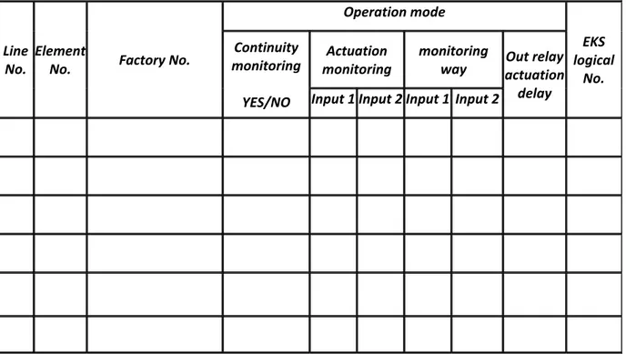
13 DESIGNER’S TABLELS ... 67
1
INTRODUCTION
1.1
Documentation
contents
The purpose of this Operation and Maintenance Documentation (OMD) is to present the application,
design and operation of the POLON 4100 fire detection and alarm control panel which constitute a
part of the POLON 4000 system. The OMD contains information necessary for the panel proper
installation, servicing and operation as well as may be helpful in fire detection and alarm system designing.
The Programming Manual (PM) constitutes a supplement to the OMD and it describes the control
panel programming process.
Line elements that interoperate with the panel and can be installed in the POLON 4100 control panel detection lines, are listed in Appendix A. Detailed information about the elements interoperation with the POLON 4100 control panel are contained in a particular device installation and maintenance manual.
The OMD is supplied to the panel user together with the device; the PM programming manual is
delivered only to trained and authorized designing and installing companies.
1.2
Control
panel
application
The POLON 4100 fire detection and alarm control panel is designed to:
1. signal a fire occurrence detected by an interoperating fire warning devices (automatic and
manual),
2. indicate a fire endangered place,
3. actuate fire protection equipment,
4. transmit a fire signal to proper services, e.g. Fire Brigades.
The control panel is intended for continuous operation in premises of low dust level at ambient temperature from ‐ 5 °C to + 40 °C and air relative humidity up to 80 % at +40 °C.
1.3
Safety
conditions
1.3.1 Electric shock protection
The POLON 4000 system fire control panels are ranked as the 1st protection class devices and can be
used only in the case of application of additional protection against electric shocks, such as zeroing or protective grounding.
230 V/50 Hz mains supply circuits insulation is reinforced and resists 2800 V voltage test; low‐voltage circuits (below 42 V) insulation is able to resist test voltage of 700 V DC. After mains circuits, the mains connectors should be protected with a factory shield.
1.3.2 Installation and equipment safety
Wire installation should be made using cables of the required fire resistance and should be properly protected in passages through fire zone boundaries. In order to avoid undesirable interaction, a
required distance between the low‐voltage installation and a power installation and a lightning protection system should be maintained. From the system electromagnetic interference immunity, it
is recommended to utilise protective grounding. Reserve power supply batteries should be
connected to the panel at the final stage of the installation.
The panel components are heat sensitive. The maximum ambient temperature should not exceed
+ 40 °C. It is forbidden to block ventilation openings placed on the panel side. The space left around the device should be big enough to secure free air flow. Air humidity in the premises where the panel operates should not exceed 95 %.
1.3.3 Repairs and maintenance
Maintenance works and periodic inspections should be executed by skilled personnel employed by
companies authorised or trained by Polon‐Alfa. Any repairs must be carried out by the manufacturer.
Polon‐Alfa bears no responsibility for the operation of any apparatus being serviced or repaired by
unauthorised personnel.
1.3.4 Fuse replacement
In the event of fuse replacement, an equivalent fuse should be used: of the appropriate type and
nominal value. The appropriate types and nominal values are contained in table 2.3.
1.4
Definitions
Addressable detection line
A detection line that enables an addressable element connection.
Side detection line
A detection line for two‐state non‐addressable fire warning devices, created using the ADC‐4001
adapter.
Addressable element
A device operating in a detection line which possesses a unique and unchangeable identity feature in the form of serial number and an element number which is assigned during system configuration. An
addressable element enables two‐direction digital data exchange with the control panel
(transmission and receiving).
Line element
An element installed in addressable detection lines (addressable element) and side lines (non‐
addressable element).
Factory (serial) number (factory address)
A unique 12‐digit number which is assigned to every addressable element during manufacturing
process. The factory number contains the addressable element type being identified by the control panel.
Line number
A consecutive number from 1 ÷ 2 range, which is assigned to an open or loop‐shaped detection line.
Element number
A consecutive number from 1 ÷ 64 range, which is assigned to an addressable element during the
detection line configuration. During normal operation, control panel intercommunicates using the
element number (short number).
Address space
A set of digit pairs composed of a line number and element number that determines all possible program element arrangements in a circuit.
Zone
Non‐maskable fault
A fault related to the EKS‐4001 element or the LK monitoring lines.
Standard configuration
A set of data that determines the control panel equipment furnishing and its operation arrangement
(e.g. addressable element declaration, element assignment to particular zones, alarm variants),
settled and loaded to the memory by the manufacturer.
User message (text)
A message on the text display (a wordy text nor longer than 64 characters each), assigned to line elements or conventional lines during programming process, utilized by the user for their installation location identification.
Quiescent (supervision) mode
An operation mode, in which the control panel is power supplied from an electric energy source that meets the settled requirements, during which no other operation mode is indicated.
Alarm (fire) mode
An operation mode the control panel triggers after receipt and verification of a fire occurrence signal from fire warning devices.
Preliminary alarm mode (first alarm mode)
An operation mode the control panel triggers after receipt of the first alarm signal from fire warning devices.
Disablement mode
An operation mode, in which it is deliberately blocked the control panel ability to receive signals from any fire warning devices and to evoke alarms, or the control panel output and/or transmission path to any fire detection and alarm system component that is a part of alarm circuit.
Test mode
An operation mode in which the control panel indicates functioning checking.
Fault mode
An operation mode in which the control panel indicates a fault of anything in alarm installation or its own circuits.
Technical alarm mode
An operation mode in which the control panel indicates actuation of any supervised external devices or a service mode of fire detectors.
POLON 4000 system digital monitoring (PMC‐4000)
A digital monitoring protocol applicable in POLON 4000 control panels.
2
DEVICE
COMPLETENESS
Table 2.1 lists the set of items which compose the POLON 4100 control panel furnishings.
Table 2.2 specifies auxiliary equipment that can be installed in the POLON 4100 control panels. This equipment should be ordered separately.
Table 2.3 contains a list of the fuses used in the control panel.
Table 2.1
Item Description Drawing
(catalogue) No. Quantity
1 2 3 4 5
Complete casing
PSC‐41 central controller module PS‐49 signalling devices board
MLS‐41 line‐controlling module board
Operation and Maintenance Documentation (OMD)
A/E342‐50.00.00‐1 B/E300‐80.00.00‐1 C/E270‐80.00.00‐1 B/E342‐03.00.00‐1 ID‐E342‐001
1 1 1 1 1
6 7 8
Servicing manual Warranty certificate Control panel package
IO‐E342‐001 1
1 1
Table 2.2
Item Description Drawing (catalogue) No.
1 Computer keyboard
Table 2.3
Item Part description Quantity
1 2
NANO 3.15 A mini‐fuse NANO 630 mA mini‐fuse
1 pcs 3 pcs.
3
TECHNICAL
SPECIFICATIONS
INPUT PARAMETERS
Control panel basic power supply voltage – 50 Hz mains 230 V AC + 10 % ‐ 15 %
Maximum power draw from mains < 250 VA
Control panel internal operation voltage – constant 24 V + 25 % ‐ 15 %
Reserve power supply source (battery panel) 2 x 12 V / 22 Ah
Battery maximum internal resistance (with cables) 1 Ω
Reserve power supply switching automatic
Battery panel charging/buffering switching automatic
OUTPUT PARAMETERS
Maximum current draw from batteries in quiescent mode < 250 mA
Maximum current draw from batteries in alarm mode (without
external devices)
< 400 mA
Maximum current draw disposable for external devices in alarm
mode (including LS signal line)
1 A
DETECTION LINES
Addressable detection lines number 2
Addressable detection line operation arrangements loop‐type (A type)
radial (B type)
Maximum detection line voltage 23.4 V ÷ 24.6 V
• addressable depending on configuration • branch ADC‐4001 • between two subsequent elements equipped with short circuit isolators 2 x 100 Ω, 2 x 75 Ω, 2 x 45 Ω 2 x 25 Ω 2 x 50 Ω Maximum addressable detection line wires capacity 300 nF
Allowable detection line quiescent current (depending on
configuration) • at maximum wires resistance 2 x 100 Ω • at maximum wires resistance 2 x 75 Ω • at maximum wires resistance 2 x 45 Ω 20 mA 22 mA 50 mA
LINE ELEMENTS – NUMERIC PARAMETERS
Number of addressable elements installed in one line, dependable on total quiescent mode, but not higher than • A type line (loop‐shaped) • B type line (radial) 64 32 Maximum number of EKS‐4001 monitoring and controlling elements • in total, connected to control panel 40 Maximum number of EWS‐4001 multi‐input controlling elements • in total, connected to control panel • connected to one detecting line 40 20 Maximum number of EWK‐4001 multi‐output controlling elements • in total, connected to control panel • connected to one detecting line 40 20 Maximum number of SAL‐4001 acoustic signalling devices • in total, connected to control panel 40
Maximum number of UCS 4000/UCS 6000 universal controlling
panels • in total, connected to control panel • connected to one detecting line 40 20 ALARMING Number of zones that line elements are program assigned to 128 Number of interdependent detector groups in a zone 2 (A and B) Fire alarm types
• 1st stage alarm
• 2nd stage alarm
1ST STAGE ALARM 2ND STAGE ALARM
Alarm variants number applicable in zones 17
Time programing ranges
• T1 time –1ST STAGE ALARM confirmation awaiting
• T2 time – recognition after 1ST STAGE ALARM confirmation
• T3 time – alarm outputs activation delay 0 ÷ 10 min 0 ÷ 10 min 0 ÷ 10 min Maximum number of saved events – (EVENT MEMORY) 2,000
Maximum number of saved alarms – (ALARM MEMORY) 9,999
INPUTS / OUTPUTS
Non‐programmable output (fault relay)
• non‐potential switchable contacts 1 A / 30 V
1 (PK1 – PU) Programmable outputs
• non‐potential switchable contacts 1 A / 30 V
• signal line of 0,5 A/24 V load
2 (PK2, PK3) 1 (LS) Programmable inputs – monitoring lines
• number
2 (LK2, LK3)
Maximum number of zones assigned to outputs (total number of
assigns to PK, LS type outputs and EKS‐4001, EWS‐4001, UCS 4000,
UCS 6000 line elements)
64,000
ENVIRONMENTAL PARAMETERS
Transportation temperature ‐ 25 °C ... + 55 °C
Operation temperature ‐ 5 °C ... + 40 °C
Allowable operation relative humidity 80 % at + 40 °C
DESIGN PARAMETERS
Casing ingress protection IP 30
Dimensions (without fixings) 420 x 384 x 115 mm
Mass (without batteries) < 7 kg
Liquid crystal display (graphical) of resolution at 320 x 240 pixels
INTEROPERATION WITH DEVICES/SYSTEMS
PS/2 standard computer keyboard PS/2
PC computer USB or RS‐232
POLON 4000 system digital monitoring system (PMC 4000) USB or RS‐232
TSR‐4000 terminal
maximum number of terminals connected to control panel
16
CONTROL PANEL OPERATION
Variable, program executed depending on premises fire scenario requirements
4
DESIGN
DESCRIPTIONS
4.1
Overall
control
panel
description
The control panel is made in the form of a metal cabinet intended for wall mounting. The cabinet
All signalling and handling elements are located on the control panel door. Electronic circuit modules and a mains power supply unit are placed inside the cabinet.
Round holes are provided (at the control panel back side top) for installation wires introduction. Below, there is a round rubber pass for introducing of mains power supply and grounding wires. It is
possible to place two 12 V 17 – 22 Ah capacity batteries inside the cabinet on its floor.
4.2
Module
arrangement
The POLON 4100 control panel module arrangement is shown on Fig. 4.1.
Note:
Any module installation or removal can be carried out only with disconnected power supply sources.
4.3
Handling
and
signalling
elements
4.3.1 Optic LED indicators
The signalling and handling elements are placed on the control panel door, which is called the TSO‐ 4100 signalling and controlling board or, in other words, the user’s console. Fig. 2 presents the signalling and handling elements arrangement.
Fig. 4.1 POLON 4100 control panel main elements arrangement
Fig. 4.2 Signalling and handling elements located on the control panel front panel
4.3.2 Control panel handling and signalling elements
Fig. 4.3 Control panel handling and signalling elements
NAME INDICATOR – Description PUSH BUTTON – Description
ACKNOWLEDGEMENT An active confirmation function Silencing of the buzzer located in the
control panel in a fire alarm, technical alarm and fault mode; in the case of two‐ stage alarming it activates T2 time
RESET An active reset (cancellation)
function Fire alarm reset (cancellation) ACTIVATION OF ALARM TRANSMISSION DEVICES Activation of at least one alarm transmission output FAULT OF ALARM TRANSMISSION DEVICES Fault of alarm transmission outputs DISABLEMENT OF ALARM TRANSMISSION DEVICES Disablement (blockade) of alarm device outputs
continuous signalling – all outputs
are disabled,
flashing signalling – some outputs
are disabled Switching on/off all alarm transmission device outputs (except permanently disabled outputs) ACTIVATED ALARM DEVICES Activation of at least one alarm output Switching on/off all alarm device outputs that meet actuation criterion (except permanently disabled outputs) FAULTY ALARM DEVICES A fault of some or all alarm device outputs DISABLED ALARM DEVICES Disablement (blockade) of alarm device outputs
continuous signalling – all outputs
are disabled,
flashing signalling – some outputs
are disabled
ALARM Collective – of preliminary alarm or
fire alarm
continuous signalling – preliminary
alarm or fire alarm is confirmed, flashing signalling – preliminary alarm or fire alarm is not confirmed
Fast access to technical alarm messages
FAULT Collective – of faults
continuous signalling – a fault is confirmed,
flashing signalling – a fault is not confirmed
Fast access to fault messages
DISABLEMENT Collective of disablement
(blockade)
continuous signalling – disablement switched on
NAME INDICATOR – Description PUSH BUTTON – Description
TEST Collective of tests being carried out
continuous signalling – testing switched on
Fast access to test messages
TECHNICAL ALARM Collective of technical alarm
continuous signalling – a technical
alarm is confirmed,
flashing signalling – a technical alarm is not confirmed
Fast access to technical alarm messages
PERSONNEL ABSENT Personnel absent mode Personnel absent mode switching on/off
DELAYS ON Delays switching on Switching on/off all delay times (T1, T2,
T3, Top)
SYSTEM FAULT A system (microprocessor circuits)
fault
POWER Control panel power supply
continuous signalling – control
panel supplied from mains, no faults,
flashing signalling – any power
supply fault
4.3.3 Numeric keypad and edition push buttons
Fig. 4.4 Numeric keypad and edition push buttons
0...9
numeric keypad
Push
button
Function
menu
control panel main menu display
esc
current operation aborting
enter
activation of a currently selected menu option and moving the cursor to the
beginning of the next line (during communique/message edition) tab
movement from one menu window to another
backspace
deleting the character to the left of the cursor and moving the text backwards one character space
space
unmarked key – inserting one character space in the cursor location
cursors
Note:
Alternatively to the keypad located on the control panel door, a PS/2 computer keyboard can be used if it is connected through a socket placed on the MLS‐41 module.
5
OPERATION
DESCRIPTIONS
5.1
General
description
The POLON 4100 control panel is a microprocessor based module‐construction device. The control
panel block diagram is presented in Fig. 5.1.
Line elements installed in an addressable detection line, after receiving an appropriate signal from
the control panel (element’s address), send relevant signals back with information about their type
through the MLS‐41 module. After an analysis of the received signals, the module passes proper
information through the control panel to the PSC‐41 central controller. Then the information is
processed and adequate signals for remaining circuits are produced.
The PSC‐41 module, fulfilling the programmed operation procedures, controls – through a bus – the relays or signalling lines located on the MLS‐41module.
The liquid crystal display, the PS‐48 main fire indicator and acoustic signalling device module, signalling and servicing elements of the TSO‐4100 panel, are controlled with the use of the µPC
microprocessor. The TSO‐4100 panel main purpose is to provide communication between the
attending personnel and the control panel.
The MLS‐41 module enables external devices control using 3 relay outputs (PK1‐PK3), 1 controlling
line (LS1) and 2 monitoring lines (LK1, LK2). Auxiliary connections are provided in the module: a socket to connect a computer keyboard, 1 RS‐232 serial connector, and 1 USB port to connect a
computer or digital monitoring, as well as the RS‐485 output to connect the TSR‐4000 parallel
indication terminals. Additionally, the module produces the following power supply voltage:
1. operating voltage: + 24 V for the control panel and + 24 V voltage for the user,
2. insulated voltage power supply: + 27 V for detection lines
3. insulated power supply voltage: + 5 V for serial outputs,
4. power supply voltage: + 5 V for the LCD display.
The PZ‐41 mains supply device is designed to provide the control panel operating voltage supply, in the case of the mains power supply outage – this function is fulfilled by a reserve battery panel.
Fig. 5.1 POLON 4100 block diagram
5.2
PSC
‐
41
central
controller
module
The PSC‐41 central controller module is equipped with the μPC (logically identified as μP1)
microprocessor circuit that ensures the control panel unfailing operation. The module is furnished
with ROM program memory (located in a separated MP‐41 module), RAM operational memory, and SETUP configuration memory (a database that determines the equipment environment and system operation arrangement).
The circuits that are provided for creation of the central panel communication bus for information
exchange and other MLS‐41 modules control are also located there.
The PSC‐41 module is equipped with its own 5 V DC and 3 V DC converters to supply own and
external electronic circuits.
5.2.1 Module signalling and handling elements
On the PSC‐41 module left inner edge there are two illuminating diodes that indicate the module
operation service status. A mini‐switch, marked as Reset μPC, is located in the board back, which is used to perform the μPC microprocessor’s restart (by a short button pressing). From the module left side, the SW1 switch is placed; the SW1 switch keys functions are described in Table 5.1.
In order to perform the K1 or K3 key operations described in Table 5.1, it is necessary to settle the
appropriate SW1 switch key in ON position, push the Reset μPC unstable switch and, after ca. 30 s,
to settle the SW1 switch key again in OFF position.
Table 5.1.
SW1 Key Position Function
K1 ON After microprocessor μPC restart, standard system configuration loading
K2 ‐ Unused
K3 ON After μPC microprocessor restart, loading standard access codes of 1
st, 2nd and 3rd level
K4 ON PSC‐41 module servicing diodes switching on
K5 ‐ Unused
K6 ON Authorisation for SYSTEM FAULT reset – the reset is executed after μPC
microprocessor reset
K7 ‐ Unused
K8 ‐ Unused
Notes:
In case the SW1 switch key 1 is settled in ON position and the PSC‐41 module is restarted, the previous system configuration is deleted and the standard one in loaded in its place.
Leaving the keys 1 and 3 in ON position can result in a loss of the entered data and is indicated as a fault.
Fig. 5.2 PSC‐41 central controller module
5.3
MLS
–
41
line
‐
controlling
module
The POLON 4100 control panel is permanently equipped with the MLS – 41 line‐controlling module
that enables external fire detection and alarm system circuits connection. This module is furnished
with:
‐ 2 L1 ÷ L2 addressable detection lines, ‐ 3 PK1 ÷ PK3 non‐potential relays:
‐ 1 PK1 (PU) non‐programmable fault relay, ‐ 2 PK2 ÷ PK3 programmable relays,
‐ 1 LS1 programmable signalling line of 0.5 A current efficiency, ‐ 2 LK1 ÷ LK2 programmable monitoring lines,
‐ 1 RS‐232 serial port (PORT1) to connect a computer or monitoring station, ‐ 1 USB port (PORT2) to connect a computer or monitoring station,
‐ 1 port to connect a PS2 computer keyboard,
‐ 1 power supply output for external devices supply – of 0.5 A load and 24 V voltage, ‐ controlling and power supply monitoring circuits (together with reserve power supply batteries).
Fig. 5.3 MLS – 41 line‐controlling module
5.4
Addressable
detection
lines
5.4.1 Detection lines types
Type A addressable detection lines – the POLON 4100 control panel loop‐shaped lines are wire
damage (short‐circuit or break) resistant. This resistance is provided by the line loop shape and short
circuit isolators built‐in system addressable elements. Apart from this, it is possible to connect a B
type open line – radial one, but in such configuration – according to the regulation in force – it cannot contain more than 32 fire warning devices. In loop‐shaped lines, one line break does not eliminate any line element. The control panel, after a damage disclosure, signals it and activates the detection line monitoring from both ends. After the break repair, the damage fault signalling is automatically removed.
A detection line which operates without a loop forming, is not break‐in‐line resistant. A break results in switching off the line elements located between the break and the line end. In radial detecting lines, after a short circuit disclosure, the closest before the short circuit isolator is automatically activated and the section located behind the isolator is cut off. In the loop‐shape layout, in case of the detecting line wires short circuit, two isolators located in the line elements closest to the short circuit occurrence are activated and – as a result of this – only the
section placed between those two elements is cut off. It is not recommended to design detection
lines with branches since a break or short circuit in a branch makes the elements located between
the damage place and the side line end disconnected, regardless the detection line operates in loop‐ shaped layout or not. If the side line appears indispensable, it is advised to decrease as much as possible (less than a dozen) the number of the line elements installed in this line.
The POLON 4000 system detection lines should be routed as follows:
1. radial lines without branches,
2. loop‐shaped lines with few branches are acceptable, but at least one addressable element
should be installed between two neighbouring branches. Such the lines routing way enables addressable elements automatic configuration. When designing addressable detection lines, the program and electric requirements stated in Table 5.2 should be observed. Table 5.3 contains current‐and‐resistance parameters and the MLS‐41 module configuration jumpers positions. Table 5.2
Parameter Value Remarks
Number of elements max 64 32 for radial line
Current max Pursuant to Table 5.3
Line resistance max 2 x 100 Ω
Line capacity max 300 nF
Table 5.3
Line No Jumper Jumper
position
Max. current
[mA]
Max. resistance
[Ω]
L1 S1 1 ‐ 2 1 ‐ 2 2 ‐ 3 20 22 50 2 x 100 2 x 75 2 x 45 L2 S2 1 ‐ 2 1 ‐ 2 2 ‐ 3 20 22 50 2 x 100 2 x 75 2 x 45 Note: In the case application of the ADC‐4001M adapter with a grounded intrinsically safe barrier in a side line, it is necessary to switch the earth fault signal off, removing the S3 jumper in the MLS‐41 module.
Fig. 5.4 POLON 4100 control panel exemplary detection lines
5.4.2 Addressable elements numbering
In POLON 4000 system each addressable element possesses a unique 12‐digit number, which is also
called the factory number, whereas the control panel in its normal operation refers to the
addressable elements using a short number (the short number – a figure from 1 ÷ 64 range). During detecting lines configuration, every addressable element factory number is assigned to a consecutive element number.
In the POLON 4000 system addressable elements can be configured in three ways:
Automatic configuration
Elements installed in the main loop are numbered in ascending order from number 1 starting from
the clamps marked as ‘Lx’ until the closest branch. Then the control panel allots consecutive numbers to the elements installed in the side line, until reaches its end. After completing allocation in the side line, it returns to the main line and continue numbering up to the next branch; afterwards the numbering process is performed in the same way as in the previous side line. The procedure is continued until all addressable elements set is used up. In this numbering method, the elements are always numbered from 1 up to n.
Configuration with verification
In this option it is necessary, on the basis of the circuit design and the control panel number allocation algorithm, to carry out a pre‐declaration, i.e. to assign (from a keyboard or computer file)
an element type to each number. Then a verification option should be run at the control panel. In
case the element types declared for given numbers are consistent with the element types allocated
in accordance with the required algorithm, the control panel automatically gives numbers to the
addressable elements.
Manual number allocation
This method allows to assign numbers to addressable elements arbitrarily. Matching factory numbers
with element numbers is carried out by typing the element number in the factory number box
manually.
Manual number declaration in the whole detection line enables arbitrary elements configuration in this line (numbers allocation can be performed in any order, not necessarily abiding the numeration order.
Notes:
The ADC‐4001M adapter with incorrectly assigned number can produce a detecting line overload. It is necessary to take the adapter out from its base and wait for at least 5 minutes. Reinstalled adapter shall draw only 150 μA from the line (the side line is automatically blocked). Before the adapter side
line re‐enablement, it should be assigned a proper operation mode in accordance with the
programming manual. Since wireless radio detectors create a line branch, automatic configuration
and configuration with verification is possible only in the case of the adapter installation in the detection line. If the adapter is installed in a radial line, its configuration should be carried our manually.
5.5
Design
guidelines
Due to installation operation reliability, a loop‐shaped detection line routing system should be
applied. Radial lines should be used only exceptionally (e.g. in case a small number of detectors must be installed in a long distance).
When designing a detection line, each addressable element must be ascribed with its own address
(element number), under which it shall be identified by the control panel. In order to assure the installation project clarity and service facilitation, it is recommended that the consecutively installed
elements possess consecutively increasing addresses – best if assigned in accordance with the control panel number allocation algorithm, which is utilized during automatic configuration.
The ADC‐4001M adapters are fitted with an illuminating diode that signals a side line detector
triggering. Therefore, such adapter can be installed in front of premises, instead of an actuation indicator. Regardless of this, it is possible to attach the WZ‐31 actuation indicators to the ADC‐4001M side line detectors as well as to 4043 and 4046 model range detectors.
It is recommended to use screened wires in the POLON 4000 system.
In the installation design process it is important to meet all requirements contained in technical specifications, it is necessary to pay special attention to the detection line capacity. The detection
line appropriate resistance should be provided as well as resistance between neighbouring short
circuit isolators.
5.6
Inputs
‐
outputs
5.6.1 General description
Inputs and outputs enable external devices connection to the control panel, alarm and fault signal
transmission, other units operation monitoring, etc. Inputs and outputs advanced software makes
the panel flexible, allowing optional installation configuration.
The relay outputs marked PK2...PK3 can be supervised (in non‐actuation state) regarding a short
circuit or break in the relay output line.
The relay output line is supervised if the line continuity monitoring is declared during the relay programming.
The output line is properly supervised if in a quiescent more the controlled device is power supplied by voltage of 6...30 V range and an appropriate jumper/bridge is set in the 1 ‐ 2 position (Fig. 5.3).
Note:
The line continuity monitoring circuit draws less than 1 mA current from an external device and it can
result in the device slight understeering. In case the device cannot be understeered, the line
continuity monitoring circuit should be program blocked, declaring the lack of output monitoring and setting the output monitoring jumper in the 2 ‐ 3 position.
5.6.2 PK relay and LS signal outputs
The PK1 relay output (PU – fault relay) is programmed permanently and operates as follows: The output is activated, if the control panel is in a fault mode (also in the case of complete power supply outage).
Other POLON 4100 control panel outputs: of relay type (PK2 ÷ PK3) as well as of potential type supervised (LS1) can be defined as:
TYP 0 ‐ inactive output,
TYP 1 – fire alarm device output,
TYP 2 – fire alarm transmission device (monitoring) output,
TYP 3 – output protective devices,
TYP 4 – fault signalling output (to the fault signal transmission device),
TYP 5 – information output,
TYP 6 – deleting output (concerns only relays).
Depending on a given output defined type, it is possible to assign it a particular variant and specified actuation time parameters.
Table 5.4
Relay State Relay contacts state
PK1 (PU) No faults, quiescent mode Closed C‐NC
General fault Closed C‐NO
PK2 ÷ PK3 No actuation criterion Closed C‐NC
Actuation criterion Closed C‐NO
Output actuation time parameters
Each output: PK relay type (except PU) as well as LS potential one can operate with a given switch‐on time program (depending also on the output defined type).
Time dependence can be based on global parameters: T1, T2, T3 and individual Top, or on a combination of those types and programming variants.
Table 5.5
Parameter Range Description
T1 time 00'00'' ‐ 10'00'' Time to confirm a 1st stage alarm
T2 time 00'00'' ‐ 10'00'' The control panel 2
nd stage alarm triggering time without a reset after the 1st stage alarm confirmation
T3 time 00'00'' ‐ 10'00'' Activation alarm outputs (TYPE 1) delay time counted from the
moment of the 1st stage alarm triggering
Top time 00'00'' ‐ 10'00'' Delay time individually programmed for each output
The LS supervised output potential line specifications
The potential output is a supervised output, i.e. it is tested by measurement of the potential line specific resistance in quiescent mode, in order to reveal a line damage, at reversed polarization way
(negative) of the output voltage. The potential line resistance (together with connecting wires
resistance) ranges between 2.7 kΩ and 16 kΩ. In case the line resistance is beyond the range
mentioned, such a condition is treated as a fault and appropriately signalled at the control panel. After the output actuation – according to a proper actuation variant – the output voltage polarization is positive.
5.6.3 Fire alarm transmission device output (TYPE 1)
Table 5.6
Variant Zone
numbers
Time
parameters Actuation criterion
1
―
T3
The 1st stage alarm at the control panel or activation with the ‘ACTIVATION’ push button
in the ‘ALARMING DEVICES’ field
2 0 ÷ 128 T3 The 1st stage alarm in assigned zones
Note:
Time elapsing is interrupted (the T3 time is set at 0 in the countdown time) and the alarm device
outputs are immediately activated in case the control panels enters the 2nd stage alarm mode. If the
T3 parameter is settled at the maximum level (10 min.), it is possible to obtain ‘only from the 2nd stage alarm’ actuation criterion.
In any time (quiescent mode) the fire alarm device outputs at an appropriate access level can be
connected (provided it has not been permanently program disabled earlier) or disconnected with a
push button located on the control panel front side:
ALARM DEVICES – ACTIVATED.
During a fire alarm the above mentioned button is used to switch the alarm devices off as well as to switch them on again (with an exception of the devices permanently program disabled). The output connection is indicated by a red diode in the box:
ALARM DEVICES – ACTIVATED.
The outputs disablement is indicated by a yellow diode in the box:
ALARM DEVICES – DISABLED ‐ flashing – some outputs are disabled, steady – all outputs are disabled.
The outputs fault is indicated by a yellow diode in the box:
ALARM DEVICES – FAULTY.
5.6.4 Fire alarm transmission device output (TYPE 2)
Table 5.7
Variant Zone
numbers
Time
parameters Actuation criterion
1 ― T1, T2 The 2nd stage alarm at the control panel
2 0 ÷ 128 T1, T2 The 2nd stage alarm in assigned zones
In any time the fire alarm device outputs at an appropriate access level can be disabled and re‐ enabled (with an exception of the outputs permanently disabled) by pressing a push button located on the control panel front side:
ALARM TRANSMISSION DEVICES – DISABLED.
The outputs connection is indicated by a red diode in the box:
ALARM TRANSMISSION DEVICES – ACTIVATED.
The outputs disablement is indicated by a yellow diode in the box:
ALARM TRANSMISSION DEVICES – DISABLED ‐ flashing – some outputs are disabled, steady – all
outputs are disabled.
The outputs fault is indicated by a yellow diode in the box:
ALARM TRANSMISSION DEVICES – FAULTY.
5.6.5 Protective device output (TYPE 3)
Table 5.8
Variant Zone
numbers
Time
parameters Actuation criterion
1 ― Top The 1st stage alarm at the control panel
2 ― Top The 1st stage alarm at the control panel until acknowledgement
3 ― Top The 2nd stage alarm at the control panel
4 ― Top The 2nd stage alarm at the control panel until acknowledgement
5 0 ÷ 128 Top The 1st stage alarm in assigned zones
6 0 ÷ 128 Top The 1st stage alarm in assigned zones until acknowledgement
7 0 ÷ 128 Top The 2nd stage alarm in assigned zones
8 0 ÷ 128 Top The 2nd stage alarm in assigned zones until acknowledgement
5.6.6 Fault/technical alarm signalling output (TYPE 4)
Table 5.9
Variant Zone/EKS/EWK
numbers
Time
parameters Actuation criterion
1 ― Top General fault at the control panel
2 ― Top General non‐maskable fault at the control panel
3 ― Top Technical general alarm at the control panel
4 ― Top General fault at the control panel until acknowledgement
5 ― Top General non‐maskable fault at the control panel until
acknowledgement
6 ― Top Technical general alarm at the control panel until
acknowledgement
7 0 ÷ 128 Top Fault in a zone
8 1 ÷ 40 Top EKS fault inputs 1 ÷ 2
9 1 ÷ 40 Top EKS non‐maskable fault inputs 1 ÷ 2
10 1 ÷ 40 Top EKS technical alarm inputs 1 ÷ 2
11 0 ÷ 128 Top Fault in a zone until acknowledgement
13 1 ÷ 40 Top EKS non‐maskable fault inputs 1 ÷ 2 until acknowledgement
14 1 ÷ 40 Top EKS technical alarm inputs 1 ÷ 2 until acknowledgement
15 ― Top Potential outputs fault
16 ― Top System fault
17 ― Top Power supply fault
18 ― Top Potential outputs fault until acknowledgement
19 ― Top System fault until acknowledgement
20 ― Top Power supply fault until acknowledgement
21 1 ÷ 40 Top EWK fault inputs 1 ÷ 8
22 1 ÷ 40 Top EWK technical alarm inputs 1 ÷ 8
Note:
Variants 1, 2, 4, 5, 15 and 16 should not be assigned to the LS potential line as it can cause (in the
case of a break or short circuit in this line) those outputs improper operation.
5.6.7 Information output (TYPE 5)
The information output can be programmed to pass information about the system (control panel and line elements) status, which does not constitute a fire alarm mode or a fault mode.
Table 5.10
Variant Time parameters Actution criterion
1 ― Disablement mode
2 ― 1 ÷ 128 zones disablement mode
3 ― Test mode
4 ― 1 ÷ 128 zones test mode
5 ― Personnel absent
5.6.8 Reset output (TYPE 6)
The reset output concerns only relays and is designed for generating a reset impulse, which lasts ca. 4 seconds after a fire alarm reset. This type can be used for example to supply and reset the detectors that require separate power supply, e.g. flame detectors manufactured by DetTronics.
5.6.9 LK monitoring output
Each of two POLON 4100 control panel monitoring outputs can be programmed in the following
variants:
1. to monitor external device actuation after an actuation criterion receipt from the declared
2. to monitor the external devices functioning,
3. as a technical alarm output.
The input status is analysed on the basis of measurement of the detection line specific resistance
(Table 5.11). The specific resistance (together with connecting wires resistance) ranges between 2.7 kΩ and 16 kΩ. In case the detection line resistance is beyond the range mentioned, such a condition is treated as a confirmation of external device actuation (variant 1) or an external devices fault (variant 2).
At the control panel any improper status is respectively signalled as a fault in the case of:
1. lack of external device actuation confirmation at an alive actuation signal of the declared relay output or potential output,
2. external device fault disclosure.
Table 5.11
Variant Function PK or LS
assigned output
Mode dependable on the detection line
specific resistance
1 Actuation
monitoring
Not activated Quiescent mode
2 k7< R < 16 k
Technical alarm R <0,9 k R > 30 k
Activated Non‐maskable fault
2 k7< R < 16 k
Technical alarm R <0,9 k R > 30 k
2 Functioning
monitoring –
Quiescent mode 2 k7< R < 16 k
Non‐maskable fault R <0,9 k R > 30 k
3 Technical
alarm –
Quiescent mode 2 k7< R < 16 k
Technical alarm R <0,9 k R > 30 k R – line specific resistance, together with connecting wires resistance
Monitoring inputs programming variants
Variant 1
A detection line input can be assigned to one of earlier declared outputs, relay type or potential one, defined as TYP‐1, 2, 3. In this case this input can be used to monitor external device actuation after an actuation criterion receipt from the declared output. Such monitoring is performed after ca. 60 s from the moment of the declared output actuation (allowable activation delay time of the controlled device).
Exemplary use of a monitoring input assigned to a relay output or potential output are illustrated in Fig. 5.6 and Fig. 5.7.
Variant 2
A detection line input can be programmed to monitor functioning of for instance external devices.
External device functioning monitoring consists in connecting the external device joint (which is usually opened) in parallel with an end‐of‐line resistor into the detection line circuit. A proper status
is observed when the monitoring line specific resistance ranges between 2.7 kΩ and 16 kΩ. An
exemplary joint connection into a monitoring line is shown in Fig. 5.8.
Variant 3
A detection line input can be can be programmed as a technical alarm input of a general purpose
monitoring input. In case resistance falling into the line technical alarm range is revealed, a technical alarm is evoked. An exemplary application is presented in Fig. 5.7 and Fig. 5.8.
Monitoring line outputs programming
Table 5.12
Variant Monitored output
type
Monitored output
number Monitoring type
0 Inactive input
1 1 – PK 2 ÷ 3 KZ actuation monitoring
2 – LS 1
2 – – KS functioning monitoring
3 – – AT technical alarm
Note:
The outputs defined as TYPE 4 should not be assigned to monitoring lines. It can result is mistaken
status interpretation in the case of actuation variant assigning to a fault of detecting or potential lines circuits.
Fig. 5.7 Exemplary use of a monitoring line assigned to a potential output
Fig. 5.8 Exemplary external device joint connection into a monitoring line
Fig. 5.9 Exemplary use of a potential line to switch an acoustic signalling device on
5.6.10 Serial ports
The following connectors are located on the MLS‐41 module board: a RS‐232 type serial port 9‐pin
joint and a RS‐485 type 2‐pin joint:
PORT 1 – to connect a computer, PMC‐4000 monitoring or a serial printer, USB – to connect a computer or PMC‐4000 monitoring,
RS‐485 – to connect the TSR‐4000 parallel signalling terminal.
The serial ports (RS‐232 and RS‐485) and USB port are isolated from the control panel in a galvanic way.
Note:
A computer which is connected to the control panel, should be necessarily power supplied from the same source that the control panel; otherwise the difference between ‘masses’ of the computer and the control panel can cause the MLS‐41 outputs fault.
Similarly, monitoring connection can bring the same result; therefore, the monitoring should be
equipped with an output isolated in a galvanic way.
The serial port and the USB port are declarable (in accordance with the Programming Manual) and
can be used for various purposes pursuantly to the declaration. The RS‐232 port connection with
external devices should be made with a standard computer cable applicable in connections with
COM type serial outputs. Table 5.13
PORT
NO.
PORT
TYPE DESCRIPTION
1 (RS)
0 Not declared
2 (USB) Speed [bps] – – –
1 (RS)
1 Configuration from the computer
2 (USB) Speed [bps] – 9600 19200
1 (RS)
2 PMC‐4000 monitoring
2 (USB) Speed [bps] 2400 4800 9600
1 (RS) 6 Serial printer (normal print)
Speed [bps] 2400 4800 9600
1 (RS) 7 Serial printer (reverse print)
Speed [bps] 2400 4800 9600
The PMC‐4000 protocol enables transmitting information of the following events to the control
panel:
‐ fire alarms,
‐ technical alarms and their reset, ‐ 2nd stage alarm,
‐ deleting, ‐ confirmation,
‐ faults and their reset,
‐ non‐maskable and their reset, ‐ tests and their reset,
‐ disablements and their reset, ‐ output actuations and their reset.
Moreover, the control panel remote handling option (SYSTEM CONFIGURATION ‐> REMOTE
HANDLING ‐> HANDLING FROM MONITORING STATION: ENABLED) enables a remote alarm or fault
confirmation, or remote alarm reset at the monitoring station.
The entire PCM‐4000 protocol description is contained in a separate document.
Note to the PMC‐4000 digital monitoring:
In order to activate the monitoring, the option PMC‐4000 MONITORING in ‘through RS‐232 (PORT1)’ should be settled in accordance with the Programming Manual.
5.6.10.1 Serial printer
The POLON 4100 control panel enable interoperation with a serial printer. The printer should be declared in accordance with the Programming Manual. Additionally, the printer should be configured as to its interoperation with the control panel (pursuantly to the printer operation manual), i.e. set the transmission parameters as per the control panel serial port settings:
‐ transmission speed at 2400 bps, 4800 bps or 9600 bps, ‐ 8 bits data (without parity);
Serial printer should support the Latin II coding standard. More detailed information – Marketing Department.
5.6.11 TSR‐4000 terminal output
The MLS‐41 module is equipped with one RS‐485 type output to connect the TSR‐4000 parallel
signaling terminals (max 16).
Maximum length of the cable laid between the control panel and the last terminal should not exceed 1,200 m. It is recommended to use the YnTKSYekw. 1 x 2 x 0.8 mm installation cable. Detailed
description of the terminals connection is contained in the ID‐E305‐001E Installation and
Maintenance Manual of the TSR‐4000 parallel signaling terminal.
5.6.12 Computer keyboard output
The MLS‐41 module contains a socket to connect a PS/2 standard computer keyboard that can be
used instead of the keypad in the handling area, and is necessary to enter the user messages. The
keyboard declaration is needless.
5.7
Power
supply
The POLON 4100 control panel can be power supplied from two sources:
1. 230 V/50 Hz alternating current mains as the basic power supply source,
2. 24 V direct current as the reserve power supply source in the form of battery panel.
The PZ‐41 power supply module of 29 V rated voltage is equipped with a mains switch. It is a cuboid‐ shaped block, placed in the control panel upper‐right corner, supplying all control panel modules and enabling interoperation with the battery panel through the MLS‐41 module.