Cengiz Alaettinoglu, Ph.D.
Chief Technology Officer
Introduction 3
Software Defined Networking
4
Controller 5
Applications 5
Carrier-SDN 6
Bandwidth Calendaring
6
Demand Placement
7
Rapid Provisioning
7
Network Access Broker for SDN
7
Integrating the Network Access Broker with SDN Applications
11
Conclusions 12
Introduction
We are seeing a tremendous innovation in connected applications driven by fast adoption of smart phones and tablets. This innovation is driven by the Internet’s end-to-end architecture where innovation can happen at the end systems (smart phones, servers, etc.) while expecting a simple set of services from the network. What is making this rapid innovation possible is a clear and well-defined set of end-system network programming APIs upon which application software can be built.
Delivery of packets between two end systems with some differentiated treatment options is the typical simple service the network provides. The network can drop or reorder packets. It may or may not honor the differentiated service requested. Indeed, most packets receive the default “best effort” delivery service. What if an application could program the network just as easily instead of expecting the best effort ser-vice? For example, what if an application could tell the network if it wanted a shortest delay or highest bandwidth path? Or, what if an application could make a request to enable communication between a set of users and a set of servers by chaining a set of logical services (e.g. routers, switches, firewalls, and load balancers) and the network magically reorganized to do that? Programming the network can open many new doors to applications.
Software Defined Networking (SDN) introduces programmability to the network. As we will see there are a few definitions of SDN, but in all definitions, SDN’s core is a set of northbound APIs that allow an applica-tion to reprogram (or to reconfigure) the network.
In this white paper, we show how Packet Design’s unique route and traffic analytics technology is well positioned to make use of and help the emergence of SDN.
Software Defined Networking
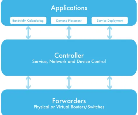
Open Networking Foundation (ONF) defines SDN as a network architecture where network control is de-coupled from forwarding and is directly programmable1. This is illustrated in Figure 1 shown below:
Figure 1: Software Defined Networking Architecture
Today’s routers and switches already have their control and data planes decoupled even though they run inside the same chassis. However, instead of being programmable they are configured. ONF’s intent is to take this decoupling further and move it out of the chassis to a centralized controller. A centralized con-troller can manage several switches.
Programmability requires northbound APIs from the devices in the network. Whether the controller is physically decoupled from the forwarder is immaterial for this purpose. The IETF I2RS working group2
has recognized this fact and started to standardize northbound APIs from the routers. Programmability without controller-forwarder decoupling is often referred to as Software Derived Networking (also SDN). Packet Design’s strategy is to work with both definitions of SDN.
Decoupling the controller from the forwarder may have an independent benefit as well. It may make it feasible to build switches from commercial-off-the-shelf (COTS) hardware components. The cost of the controller would likely be more than offset by inexpensive switches. When the forwarder and the control-ler are decoupled, ONF’s OpenFlow3 and IETF’s ForCES4 protocols can be used between the controller and
the forwarder to program the forwarder. In this SDN scenario, programmability is necessary but rather secondary to decoupling.
Controller
Service, Network and Device Control
Forwarders
Physical or Virtual Routers/Switches
Applications
Controller
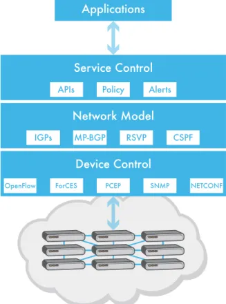
The key component of SDN architecture is the controller. The controller provides its own northbound APIs to the applications and can facilitate programming, reorganizing, and reconfiguring the network on behalf of the applications. The controller may use OpenFlow, ForCES, PCEP5, NETCONF6, SNMP7 or even
proprietary mechanisms to program the forwarders. The controller tracks all application requests, main-tains a model of the network topology and traffic loads, uses this to compute paths for the applications, and programs the forwarders. A typical controller architecture is illustrated in Figure 2.
Figure 2: Controller Architecture
Applications
The most prominent SDN application to this point is network virtualization. Many modern applications are being built as cloud applications so that users can access them regardless of their location or the device they are using. The cloud is a collection servers often running in virtual machines (VMs). As the application user base grows (or shrinks) new VMs are added (or deleted). As the user geography shifts, the VMs are migrated to better serve the user group. VM migration can also help provide business continuity during rolling black-outs or natural disasters such as hurricanes, and tsunamis. Adding, deleting and migrating VMs can all be done programmatically. However, the network needs to be reconfigured to reflect these changes. This is performed by humans and is often a lengthy and error-prone task. Network virtualization enables these reconfigurations to be programmed by the VM management systems.
Service Control Network Model Device Control
Most network virtualization applications create an overlay network between virtual switches (vSwitches) that connect the VMs. Controllers program these vSwitches using OpenFlow or XMPP8. To coordinate the
VM migration, different controllers may use multiprotocol BGP (MP-BGP) to communicate with each other; one controller withdraws the VM attachment and another one announces it. All controllers receive these MP-BGP messages and program their switches with the VMs’ new locations. Some controllers take this a step further and use MP-BGP to also connect the VMs in the cloud to the physical servers in the enterprise using Layer 2 or Layer 3 VPNs.
A further variation of network virtualization involves insertion of services such as firewalls, load-balancers, CE and PE routers between the various parts of the virtual network. This is referred to as service chaining. To achieve programmability, these services themselves need to be virtualized. The Network Function Vir-tualization (NFV) group of the European Telecommunications Standards Institute (ETSI) is currently work-ing on definwork-ing these services9.
Carrier-SDN
Software Defined Networking definitely has caught the attention of both wired and wireless carriers. While a killer application for carriers has not yet surfaced, the following are some applications that are being considered.
Bandwidth Calendaring
Applications make API calls to a bandwidth broker to request a certain amount of bandwidth be allocat-ed to themselves, either immallocat-ediately or at a future time. The broker either accepts the requests or denies them. If it accepts them, it may route the applications’ traffic on either existing paths or may set up new ones.
SDN is a natural way to implement bandwidth calendaring. After receiving the request, the controller computes a path that satisfies the requirements and sets it up using OpenFlow, ForCES or PCEP.
In a carrier network, it is not realistic to expect all applications to make all requests via the broker. Many applications do not know their needs apriori and making the request may also introduce additional laten-cy. In addition, the sheer number of flows on carrier networks is just too large to be handled by the broker (and the per-flow paths are too numerous to be handled by the switches) in a scalable fashion. Hence, the network needs to operate with both conforming and non-conforming applications. This poses a big chal-lenge since the broker cannot monitor all traffic demands accurately (and basing bandwidth decisions on instantaneous link utilizations has been proven to be unreliable10). Packet Design’s unique method for
Demand Placement
In this application, users request to access some content (e.g. a video file) that is replicated and distributed geographically. The demand placement application directs the user to the closest copy of the content. This is a win-win situation for both the carrier and the user; the user has a better experience since the copy of the content is closer, and the carrier does not need to transmit the content across its network for every user that wants it.
There are already non-SDN solutions to this application. For example, GeoDNS11 which is based on the
domain name system, is widely deployed. Indeed, several carriers feed proximity matrices from Packet Design’s route analytics technology to their GeoDNS systems. Demand placement is an ideal application for SDN.
Rapid Provisioning
A common criticism of carriers is that even the simplest forms of provisioning take days or even weeks to perform. There are often good reasons for this. For example, configuration changes typically must be done during maintenance windows and require expensive human resources, both of which need to be scheduled. A request may also involve physical resources (such as ports) that may not be immediately available.
Removing the human involvement from provisioning saves a very precious resource, the operator, but more importantly reduces possible human-error. Programmatic provisioning of complex BGP routing policies has been successfully deployed by many carriers12,13. Another recent example is the use of Session
Border Controllers to program carrier edge routers to better deal with surges in video traffic14.
Network Access Broker for SDN
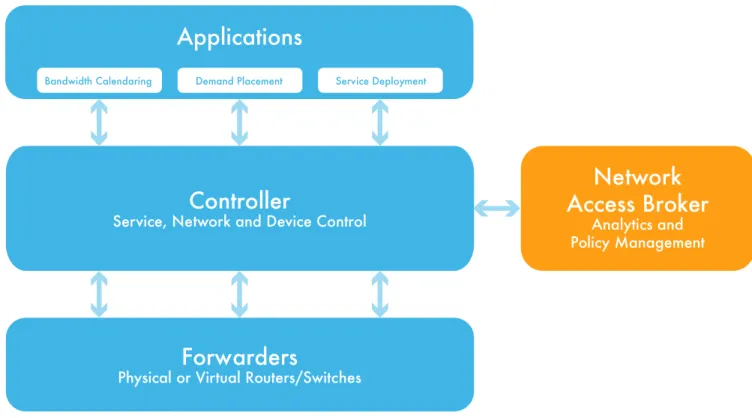
Whether it is the network virtualization application for cloud operators, bandwidth-calendaring applica-tion for carriers, or indeed any SDN applicaapplica-tion, the moment the traffic hits the wide-area network (WAN), resources become scarce. Packet Design believes that the SDN architecture should be augmented with a network access broker that checks whether the required resources are available. This augmented archi-tecture is illustrated in Figure 3 (located on the following page). Note that the network access broker may exist as part of the controller.
Figure 3: SDN Architecture with Network Access Broker
The role of the network access broker is to verify if the network can handle the traffic demands of the ap-plication without impacting other apap-plications adversely.
To do this, the network access broker needs to maintain an accurate model of the network. This model includes the IGP topologies, MP-BGP Network Layer Reachability Information (NLRI), as well as current and past traffic loads. IGP topologies are important because ultimately paths will be computed over them. MP-BGP NLRIs are important because many applications will state their requests using them (e.g. some overlay SDN solutions use MP-BGP to move VMs around). It is easy to understand why current traffic loads are important but it may not be as obvious why historical traffic loads are also important. If an application is going to run for a long time, it is important to predict traffic loads in the future. For example, a request that is made in a trading network a few seconds before financial markets open may not be allowed to pro-ceed as the traffic loads will change dramatically once market data starts flowing. Past traffic volumes can be used to predict future traffic profiles and these profiles can determine whether the application should be permitted to run or not.
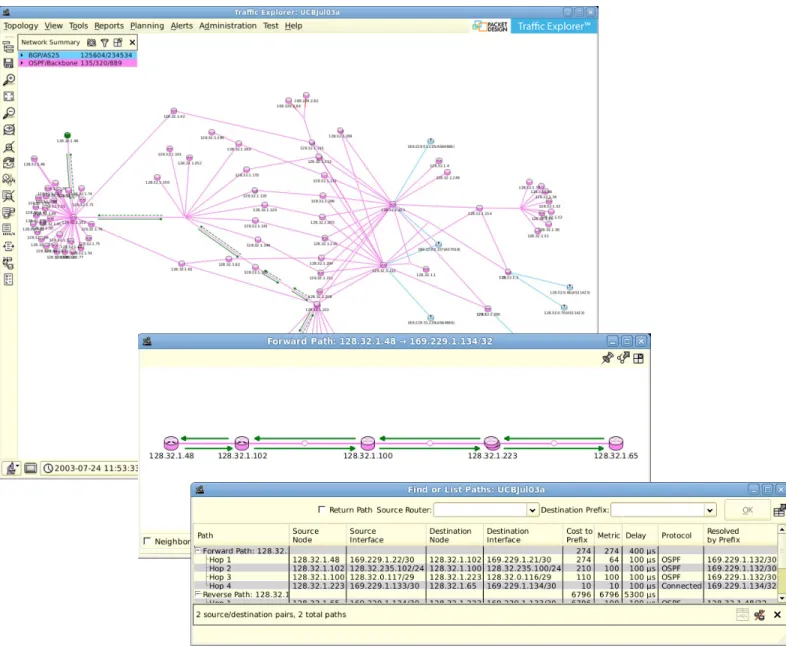
While the notion of a network access broker makes sense, it is hard to deliver because it requires unique insight into real-time and historical routing operations and traffic flows. Fortunately, current Packet De-sign technology makes it possible. Packet DeDe-sign’s Route Explorer™ (see Figure 4) provides a very detailed model of network routing, including the IGP topologies, RSVP-TE tunnels15, MP-BGP, Layer 2 and Layer 3
VPNs. Indeed, the Route Explorer model is more detailed than the one found in a regular router. For
exam-Controller
Service, Network and Device Control
Forwarders
Physical or Virtual Routers/Switches
Applications
Bandwidth Calendaring Demand Placement Service Deployment
Network
Access Broker
Analytics and Policy Management
ple, the model includes topologies for all IGP areas and Autonomous Systems (AS) whereas a router only knows of the topologies for IGP areas to which it is connected. Route Explorer maintains this model in real time by tapping into routing protocols and can compute both shortest and constrained paths across networks spanning multiple IGP areas and BGP ASs.
Figure 4: Route Explorer Maintains a Detailed Model of Network Routing
Packet Design technology also collects flow records from the network and provides Internet as well as Layer 2 and Layer 3 VPN traffic visibility (see Figure 5). Because it taps into Route Explorer’s network model, for each flow it can identify the service to which the flow belongs, where it entered the network (ingress router, VRF, interface and AS), where it will exit the network (egress router, VRF, interface and AS), and what path it will take along the way, including any RSVP-TE tunnels. With this information, it is possible to build real-time and historical traffic profiles for each link, tunnel, VPN service, ingress and egress router, and VRF, as well as traffic matrices between any two routers.
Figure 5: Packet Design Enables Real-time and Historical Traffic Profiling
An important element of the network access broker which is key to viable SDN architecture and deploy-ment is the ability to predict the impact of change to network routing topologies and traffic flows. Unique Route Explorer planning capabilities (see Figure 6) make it possible to model modifications to the network model and to flow records in real time and analyze their impact. For example, using the technology, it is straightforward to simulate moving a VM, whether it is inside a VPN or not, from one location to anoth-er, as well as all the flows originating from it. Route Explorer reroutes all flows to and from this VM along paths to and from its new location. It also analyzes and visualizes the impact; for example, if the move will create congestion on any of the new network paths and if so, what other services are effected. This use case is directly applicable to the network virtualization application.
Figure 6: Modeling Network Routing Changes in Real Time
It is also possible to model the impact of adding a new service (see Figure 6). The service definition is com-prised of the points of attachment to the network, the amount of traffic between these points and the differentiated service desired. Packet Design’s technology computes the paths between these attachment points and reports whether or not there will be congestion on any of the links or if any RSVP-TE tunnels will need to reserve additional bandwidth. This use case is directly applicable to the bandwidth calendar-ing application. Note, the use of RSVP-TE with bandwidth calendarcalendar-ing is optional. If it is included, it does not need to be at a per-flow level, it could be at a macro level between the core routers.
Integrating the Network Access Broker with SDN Applications
Packet Design software is deployed at over five hundred service providers, including almost all of the Tier-1 service providers, enterprises and government agencies. All of these deployments are inherently ready to be integrated with SDN applications.The Packet Design modeling technology provides an XML-RPC16 based API to all of its reports and
plan-ning features. Hence, it is SDN ready and is already being used by one service provider in its SDN proto-type deployment.
Conclusions
Packet Design provides unique capabilities for modeling network topologies, including IGP areas, BGP ASs, RSVP-TE tunnels, and Layer 2 and Layer 3 VPNs. The network model is augmented by the recording and analysis of path-aware traffic flows to compute real-time and historical traffic profiles. These network models and traffic load profiles are essential to any wide-area SDN application and are made available via an XML-RPC programming interface.
Packet Design’s network model and traffic matrices are available today. They are available for a variety of network deployment models including networks with or without RSVP-TE tunnels. Unlike some SDN solu-tions, deploying a full mesh of RSVP-TE tunnels is not required. In addition, while a new topology collec-tion protocol, such as BGP-LS17, may simplify collection, it is not required to build the network model and
traffic matrices.
The Packet Design monitoring, diagnostics, planning and reporting value propositions are directly appli-cable to SDN deployments. Whether the network is programmed or configured (or a combination), net-work performance can become suboptimal under a variety of conditions, including link or node failures. SDN introduces additional risks, including failure of the controller itself and the possibility of multiple controllers issuing contradictory instructions to forwarders. Packet Design’s SDN-enabling technology can compare and contrast network state to a baseline and find the root cause of these problems quickly.
To learn more about Packet Design and Route Explorer, please:
• Email us at [email protected]
• Visit Packet Design’s web site at www.packetdesign.com
• Call us at +1.408.490.1000
Corporate Headquarters
Packet Design 2455 Augustine Drive Santa Clara, CA 95054 Phone: 408.490.1000 Fax: 408.562.0080References
1. Open Network Foundation FAQs (https://www.opennetworking.org/about/faqs) 2. IETF I2RS Working Group Charter (http://datatracker.ietf.org/wg/i2rs/charter)
3. OpenFlow Switch Specification, Version 1.3.2, April 2013 (https://www.opennetworking.org/sdn-re-sources/onf-specifications/openflow)
4. ForCES: Doria, A., Ed., Hadi Salim, J., Ed., Haas, R., Ed., Khosravi, H., Ed., Wang, W., Ed., Dong, L., Gopal, R., and J. Halpern, “Forwarding and Control Element Separation (ForCES) Protocol Specification”, RFC 5810, March 2010. IETF Working Group Charter (http://datatracker.ietf.org/wg/forces/charter)
5. Vasseur, JP., Ed., and JL. Le Roux, Ed., “Path Computation Element (PCE) Communication Protocol (PCEP)”, RFC 5440, March 2009.
6. Enns, R., Ed., Bjorklund, M., Ed., Schoenwaelder, J., Ed., and A. Bierman, Ed., “Network Configuration Protocol (NETCONF)”, RFC 6241, June 2011.
7. Presuhn, R., Ed., “Version 2 of the Protocol Operations for the Simple Network Management Protocol (SNMP)”, STD 62, RFC 3416, December 2002.
8. Saint-Andre, P., “Extensible Messaging and Presence Protocol (XMPP): Core”, RFC 6120, March 2011. 9. ETSI NFV (http://portal.etsi.org/portal/server.pt/community/NFV/367)
10. A. Khanna and J. Zinky, “A Revised ARPANET Routing Metric” In Proceedings ACM SIGCOMM 1989, pag-es 45-56, September 1989.
11. GeoDNS. (http://en.wikipedia.org/wiki/Geodns)
12. Alaettinoglu, C., Villamizar, C., Gerich, E., Kessens, D., Meyer, D., Bates, T., Karrenberg, D., and M. Terpstra, “Routing Policy Specification Language (RPSL)”, RFC 2622, June 1999.
13. IRRToolSet RtConfig (http://irrtoolset.isc.org)
14. “Sonus & Juniper Team on SDN” (http://www.lightreading.com/sonus--juniper-team-on-sdn/240155668)
15. Awduche, D., Berger, L., Gan, D., Li, T., Srinivasan, V., and G. Swallow, “RSVP-TE: Extensions to RSVP for LSP Tunnels”, RFC 3209, December 2001.
16. Simon St. Laurent, Joe Johnston, Edd Dumbill. (June 2001) Programming Web Services with XML-RPC. O’Reilly. First Edition.
17. H. Gredler, J. Medved, S. Previdi, A. Farrel, S. Ray, “North-Bound Distribution of Link-State and TE Infor-mation using BGP”, Internet Draft, May 2013 (http://tools.ietf.org/html/draft-ietf-idr-ls-distribution-03).